INSTALLING A SUPERCHARGER AND INTERCOOLER ON A 948, 1098, OR 1275 A-SERIES MG MIDGET, AUSTIN HEALEY SPRITE, OR MORRIS MINOR
Please contact us if any aspect of these instructions is unclear, to have your installation tips or photos posted on this page, or to publish your performance data in the section listed below.
For an overview of this project, click here.
For FAQs, click here.
For a parts list and cost estimates, click here.
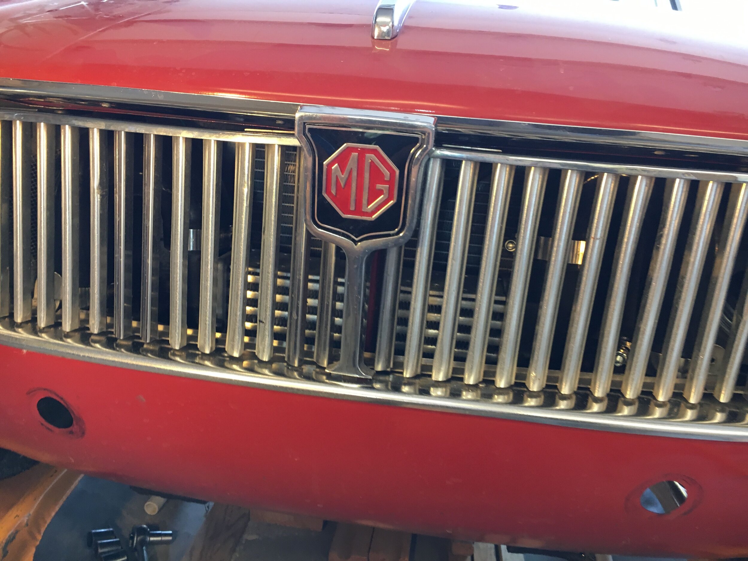
These instructions apply to the A-Series engine as mounted longitudinally in the MG Midget, Austin Healey Sprite, Bugeye Sprite, and Morris Minor (the latter cars require different intercoolers due to limited space behind the grille) as shown in this brief video clip:
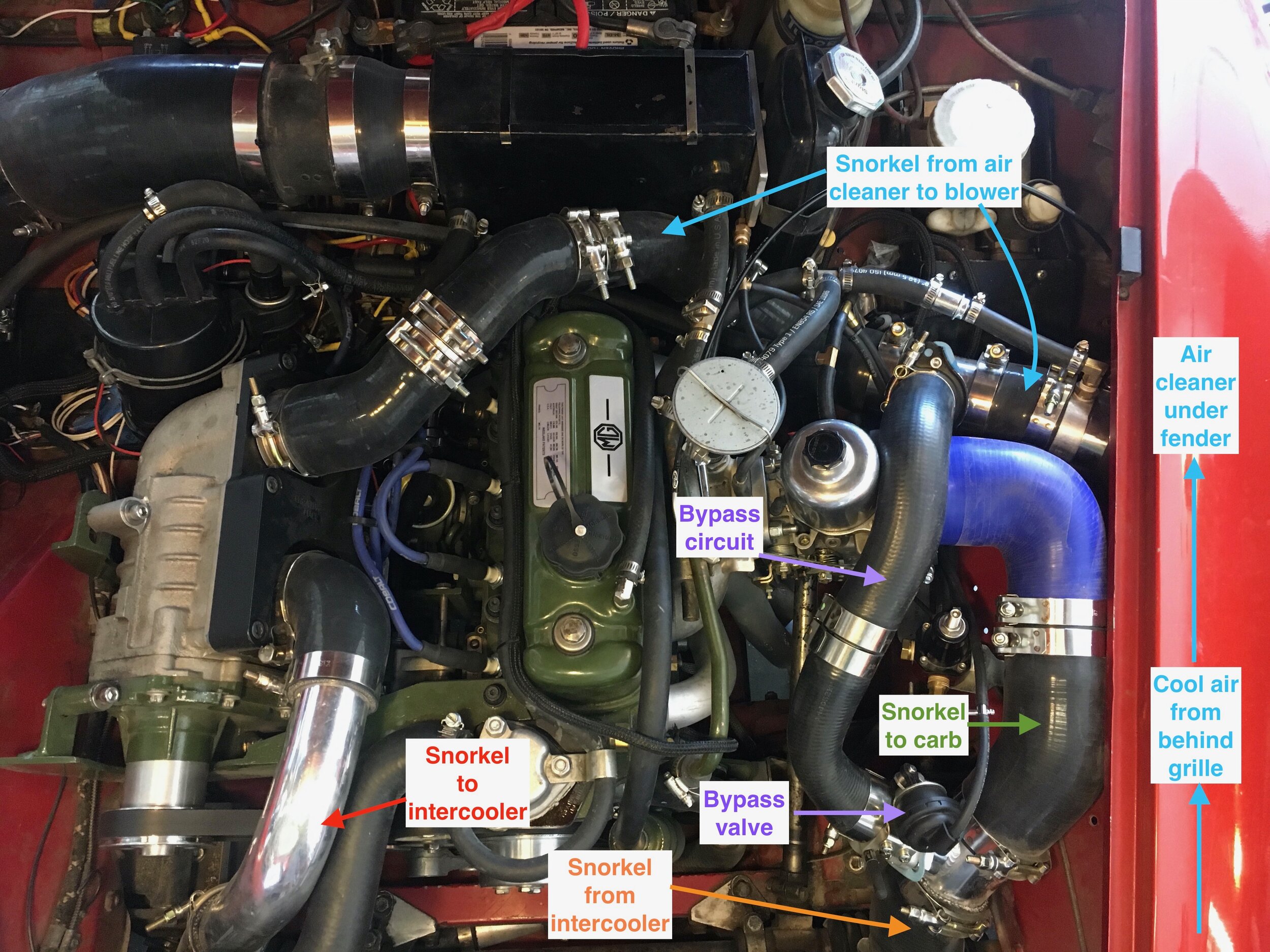
This diagram shows the flow of air through the system and identifies the related components under the bonnet.
*Note that this photo and some others in these instructions are dated re: vacuum hose routing, as unfortunately the author’s “test mule” has been sold and not yet replaced. We will endeavor to correct the related sections but feel free to to email any questions via the contact page for a prompt response and clarification:
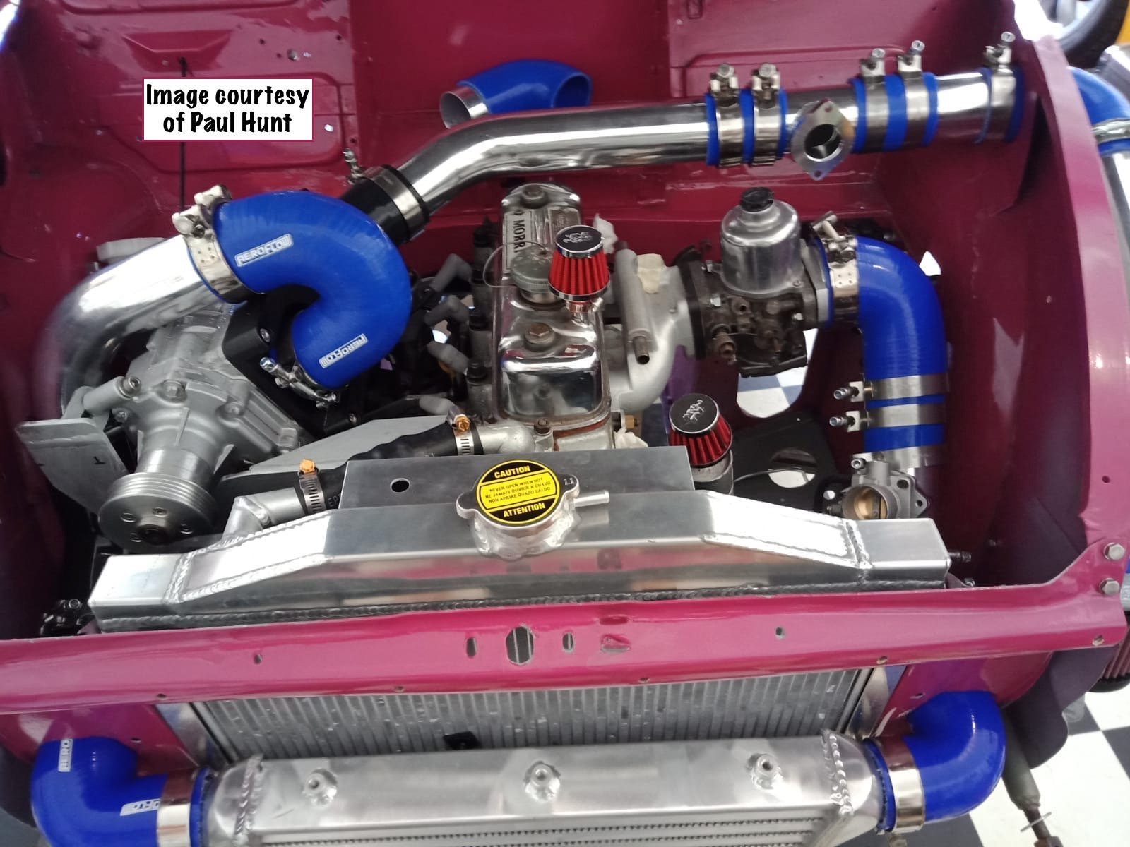
This beautifully laid out Morris Minor engine bay takes full advantage of the roomy compartment:
Here is a video showing acceleration from 0-75 mph up a gentle grade with a 2.9” supercharger pulley fitted to an internally stock 1275 A-Series engine, which generated 5.0 psi boost at 6,000 ft. / 1,829 m. elevation. The temperature was 85 F. / 29.4 C:
Compare the above to this 0-96 mph ride-along in Doug McConnell’s car, running a supercharger-specific cam, 3.1” blower pulley and 3.55 differential, which developed 3 psi of boost at 89’ above sea level…
As for the sequence of installation, you may perform this conversion in stages to suit your budget and available time—and continue driving naturally aspirated. The only exception is that you must convert to a serpentine belt drive before completing the front supercharger mount, which involves two final welds that require aligning the blower pulley with the water pump pulley.
The following hyperlinks will let you jump to any section of these instructions you wish:
convert to serpentine belt drive
install the supercharger mounts
fabricate the supercharger mounts
align the pulleys
install the idler pulley
relocate the horns
install the intercooler
modify the bumper
install an intercooler intake grille
reroute the fresh air intake (heater)
relocate the ignition coil
install a high-pressure fuel system
create or modify a vapor recovery system
plumb and adust the fuel pressure regulator
wire the high pressure pump
replace the supercharger pulley
prepare the supercharger
install the eaton m45 manifold
install the supercharger
install the serpentine belt
plumb the intercooler
bypass valve & intake tract
modify the pcv system
prepare the carburetor
tuning the system
compare & publish your results
select & harvest a used supercharger
rebuild a supercharger
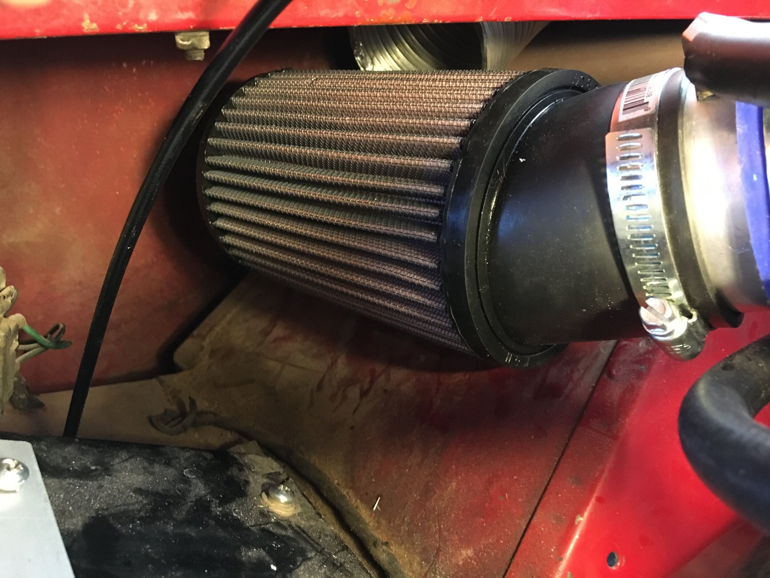
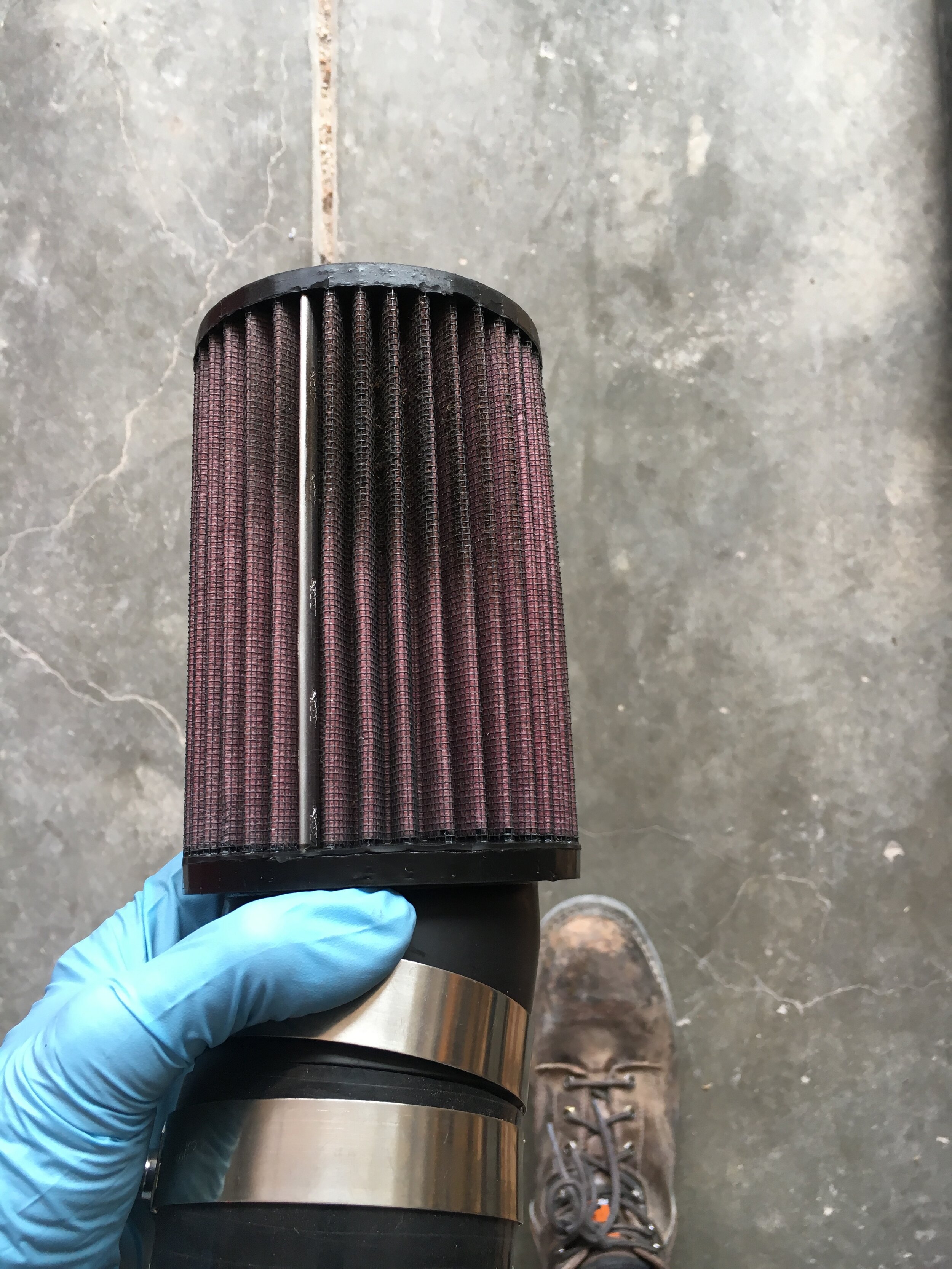
install a ‘stealth’ cold air intake
convert to serpentine belt drive
A good starting point (though not the only one) is to convert your naturally aspirated A-Series engine to a serpentine belt drive. Once this is accomplished, you can continue to drive your car while installing the remaining components as your budget and time permit.
The process is covered on a separate page on this website, linked here: Converting to Serpentine Belt Drive.
install the supercharger mounts
Regardless of whether you have paid someone to weld up your mounts or fabricated them yourself, you may wish to install them and run naturally aspirated while you complete other aspects of the conversion. If you do so, here are a few things to watch out for.
SECTION A: The Front Mount
STEP 1 - Remove the short serpentine belt using a 3/8” ratchet drive:

STEP 2 - Loosen the last head nut in the torquing series, which is immediately behind the thermostat housing (except for A+ engines with an extra stud: contact us for details), and slip the front mount into place.
Loosening and re-torquing this nut will not affect head gasket sealing:

Note that if you are supercharging a 1275 engine and have an OEM-pattern, down-flow radiator or the VW Rabbit (Golf) radiator shown in these instructions, you will need a Creative Spridgets thermostat housing spacer.
You will not need the spacer if: (i) you have a later-model crossflow radiator, as the thermostat housing directs the top hose toward the left-hand side and away from the front supercharger mount; or (ii) you have either a 948 or 1098 engine, because the thermostat housing studs are oriented differently and direct the top hose forward and away from the supercharger mount.
Use two Moss gaskets 296-381 or equivalent (one above and the other below the adapter), and coat both sides of both gaskets with an even but thin film of Permatex Ultra Gray or Yamabond for best sealing.
STEP 2 - Install the support strut, but do not fully tighten the bolts just yet:
STEP 3 - Check that the mount’s vertical surface is perpendicular to the head, or parallel to the face of the alternator pulley (though obviously aft of it), and reinstall the washer and nut. Now, torque to the correct specifications (most often, 50 ft. lbs.):

STEP 4 - Securely tighten the bolts at both ends of the support strut, and if continuing to run naturally aspirated, replace the shorter serpentine belt.
SECTION B: The Rear Mount
Before you begin, note that the 8-1/2” long, 5/16-18 bolt that serves both as the alternator pivot and idler pulley mount is too long to insert from the front without removing the electronic fans (if you have those instead of the OEM plastic propeller):

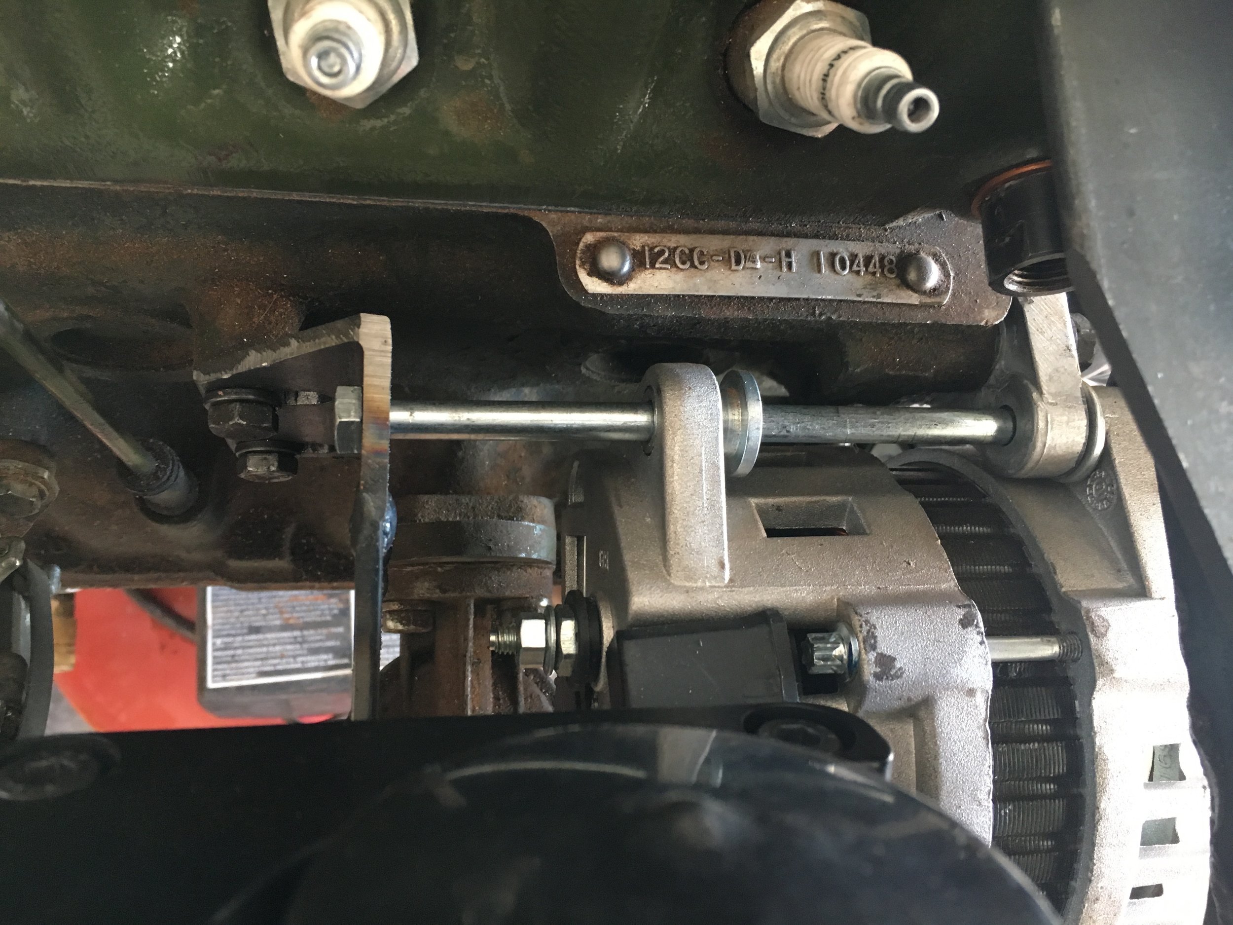
STEP 1 - Bolt the rear mount to the engine block using the OEM 5/16-24 bolts and lock washers. Then insert the long alternator pivot bolt—which serves as the idler pulley mount—from the rear as shown below:

STEP 2 - If running naturally aspirated, skip to Step 3.
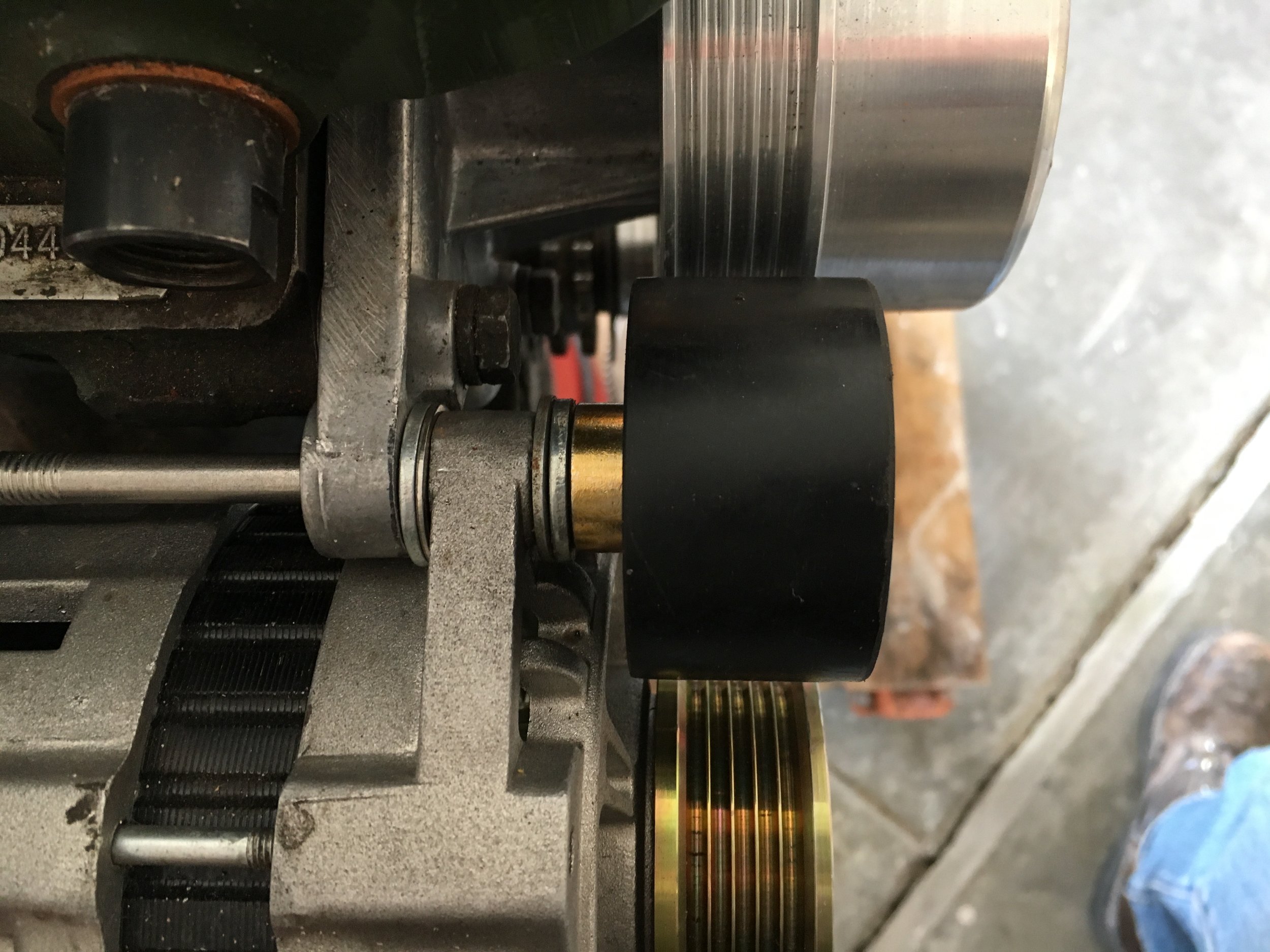
If ready to spin the blower, the combination spacer and idler bushing goes on the front end of the bolt as shown below, to support the idler pulley. The front of the pulley should get a Grade 8 washer but must receive a nylock nut (a regular nut was used just for the pictures).
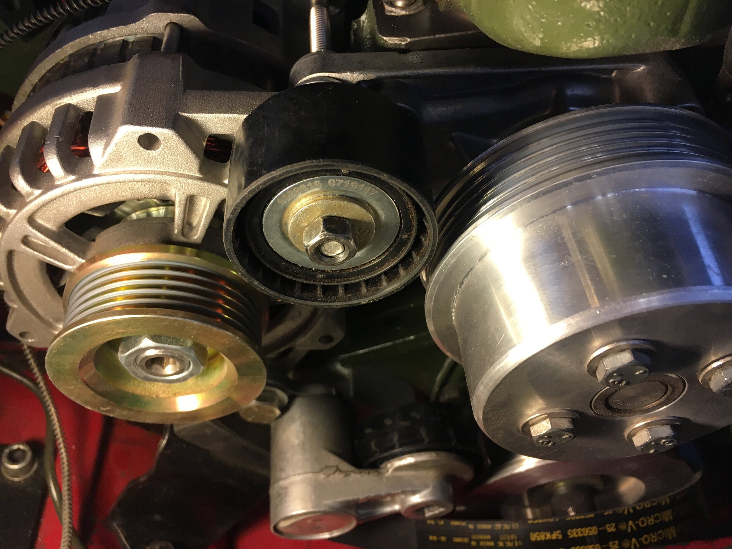
STEP 3 - If running naturally aspirated, as you can see in the first above photo, the bushing and long bolt will interfere with the shorter serpentine belt.
The fix is simple. Place the spacer and its washers on the rear of the bolt in the interim, which will also help avoid losing it, and affix a small washer and locknut to the front end of the bolt:
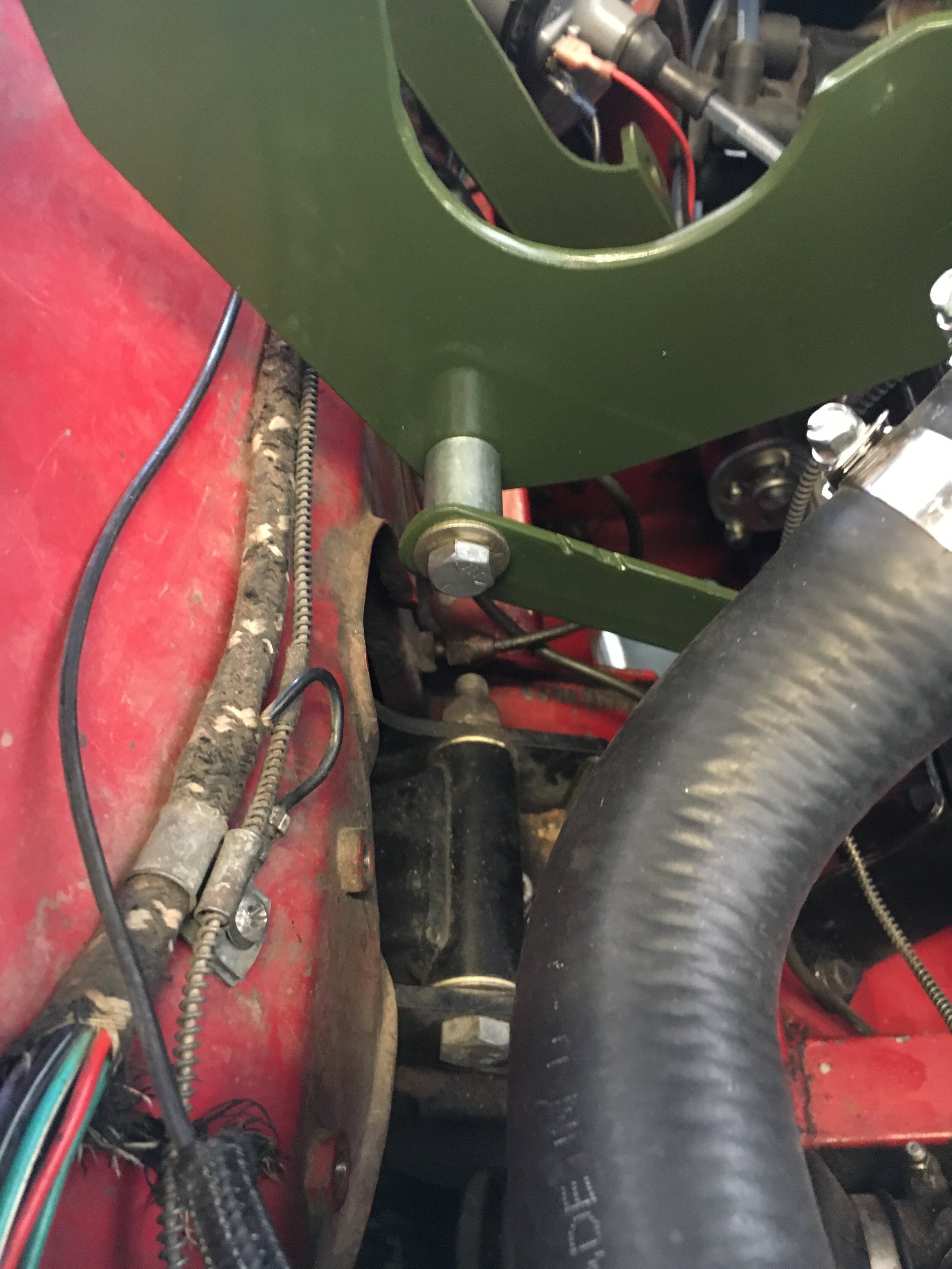
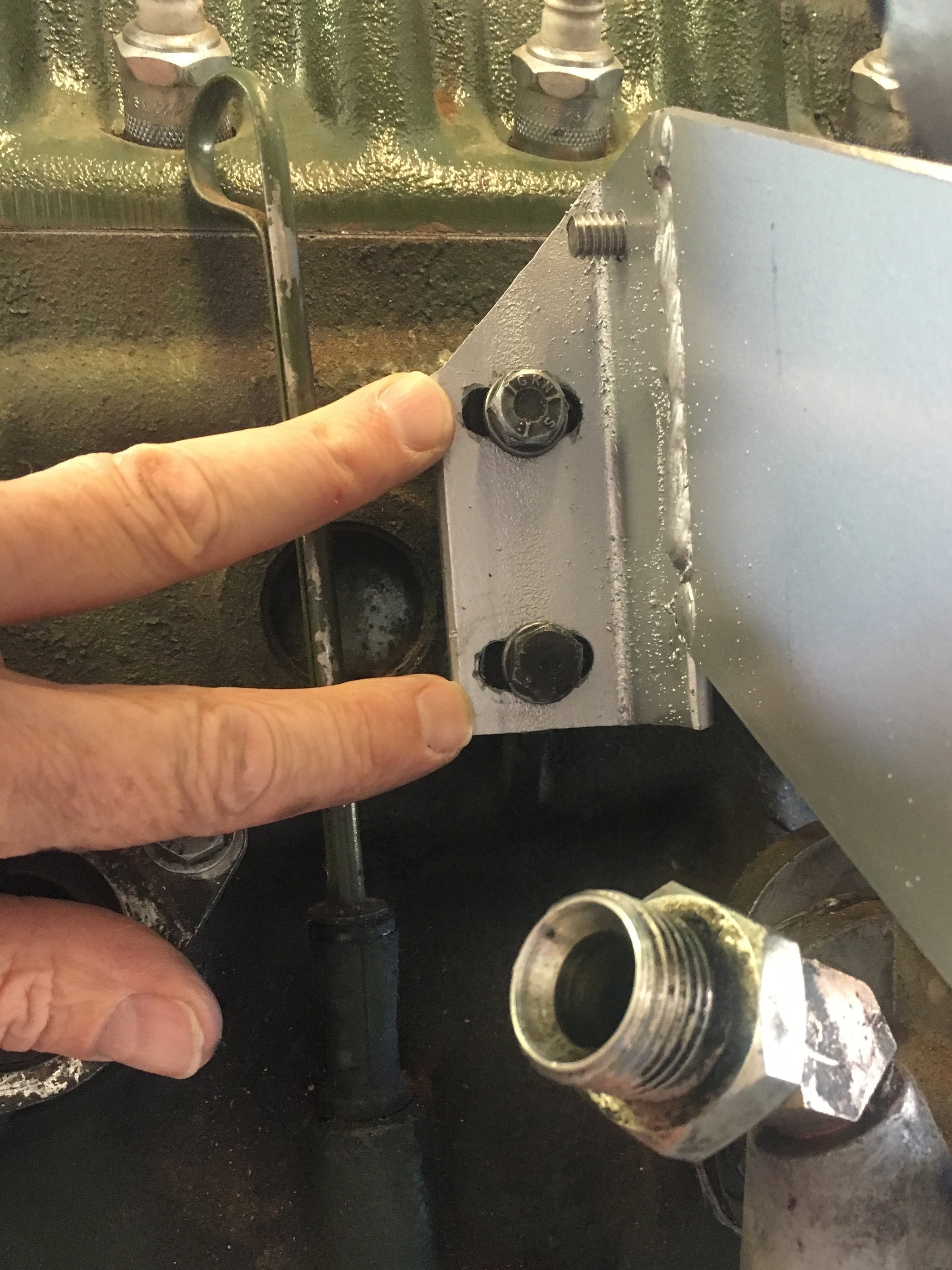
STEP 4 - Check to make sure the rear mount clears both the wiring loom and the brake union, if it is located on the right-hand inner fender:

Here is a UK right-hand drive car. Note that the owner had to cut a small relief into the rear mount to clear the steering column. This will not significantly weaken the mount:

However, early cars like the 1967 MG Midget test mule shown in these pictures had a union that incorporated a brake light pressure switch. It is possible that the sensor electrodes may not clear the mount.
The two solutions are to either install an NPT plug or replace the union—as in the above photo—and add a later model mechanical brake light switch to the pedal box, or try and bend the sensor’s electrodes so that they do not contact the mount. If you attempt the latter solution, make sure that the electrodes will not touch the mount, or there could be a short-circuit and fire hazard.
fabricate the supercharger mounts
One of the most satisfying, money-saving stages of this conversion is fabricating the steel mounts that attach the supercharger to the ignition side of the engine.
Even if you have never fabricated a part using mild steel, the material’s inherent characteristics make it amenable to a variety of hand and power tools. Also, the design of the mounts is relatively forgiving. In short, fabricating the mounts is within the skill set of an average amateur MG mechanic.
Indeed, the author had never welded before undertaking this project—aside from practicing to get familiar with his new welder.
With a single exception, when fabricating the mounts, you should refer to the free downloadable drawings with specifications available on the Purchase Page.
The exception is welding up the front mount’s components, which in the drawing indicates involves aligning certain corners. Because the short angle creating the corner of the outboard component could vary (due to stylistic choices or inaccuracy in cutting the part), you should use the index-and-measurement method set forth in these instructions to weld the two components together.
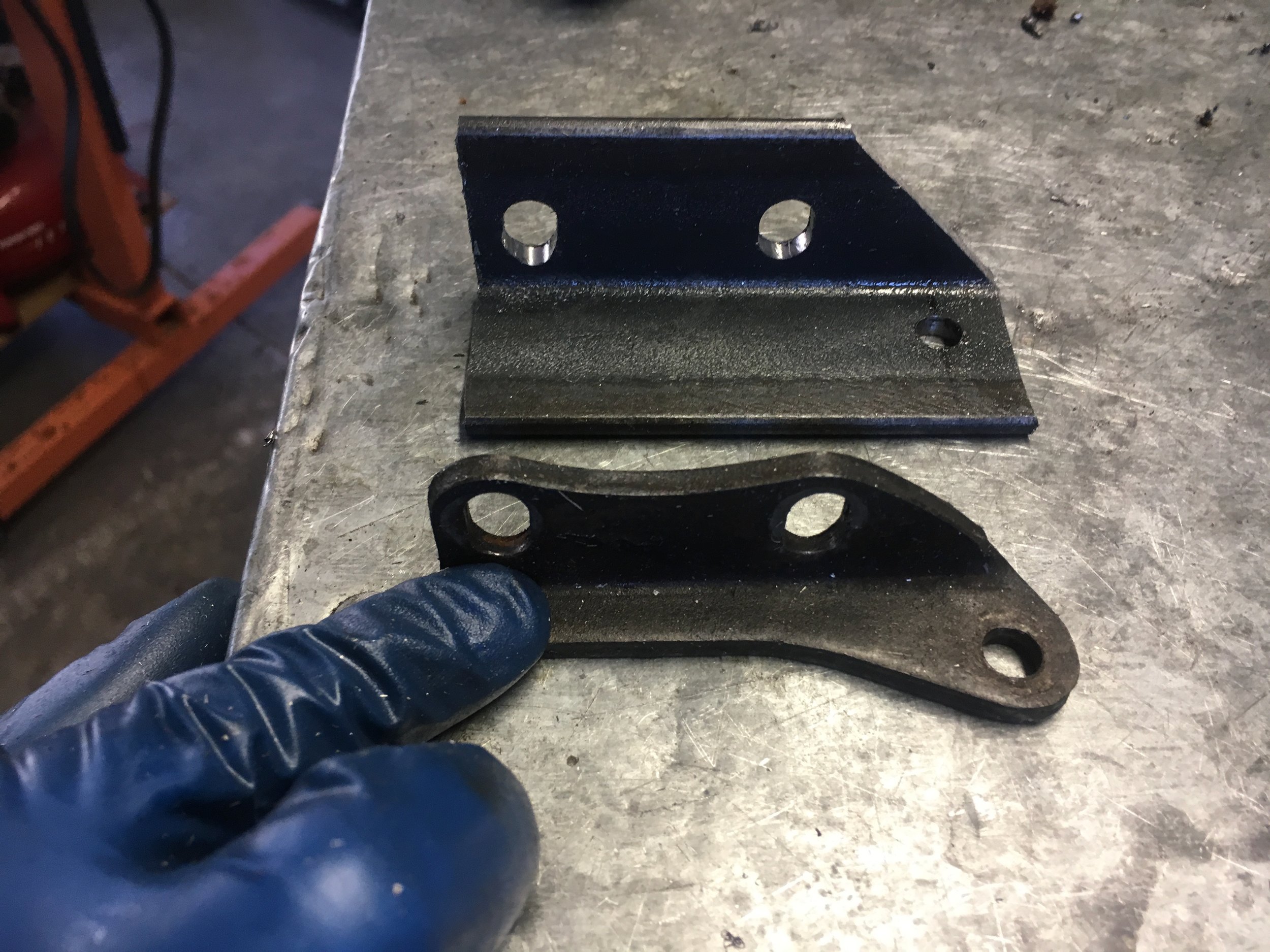
That said, below are photos of the components you will make (except for the simple support strut, which is cut and drilled once the front mount is bolted onto the engine), and then either weld together or hire someone to do that for you.
Note that the time you are charged to weld up the components should be not much more than an hour, if you deliver the parts clean and with the anti-corrosion coating stripped along the mating surfaces (not yet done in the below photo).
Indeed, the only weld that involves a critical measurement attaches the two components that make up the front mount—and you will provide the welder with the free printed diagrams and foolproof index marks on the front mount components, as shown later on.

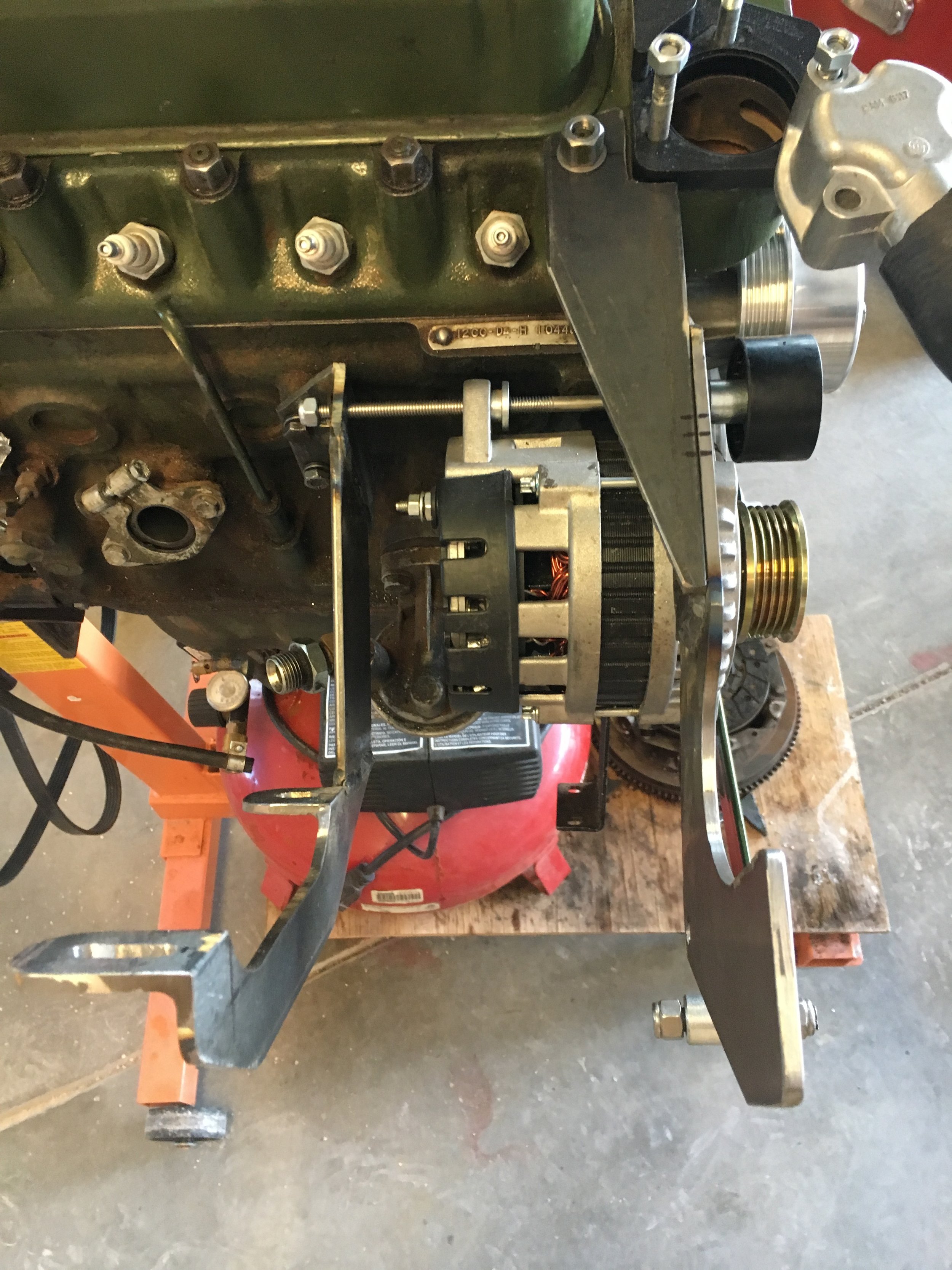
Below is a finished set of front and rear mounts (and serpentine belt pulleys) fitted to an A-Series engine.
*Note: the front mount in this image lacks two slotted holes to fit a second idler pulley that is necessary for either an early down-flow radiator or the VW Rabbit (Golf) radiator conversion that the author is running. This is discussed later on.

The above photo shows the inexpensive, late-model Saturn CS-121D alternator recommended in the parts list. However, this conversion is compatible with other charging options. Contact us for details.
SECTION A: The Rear Mount
Review the free downloadable CAD drawings to familiarize yourself with the design. The rear mount is composed of three components welded together with simple butt joints.
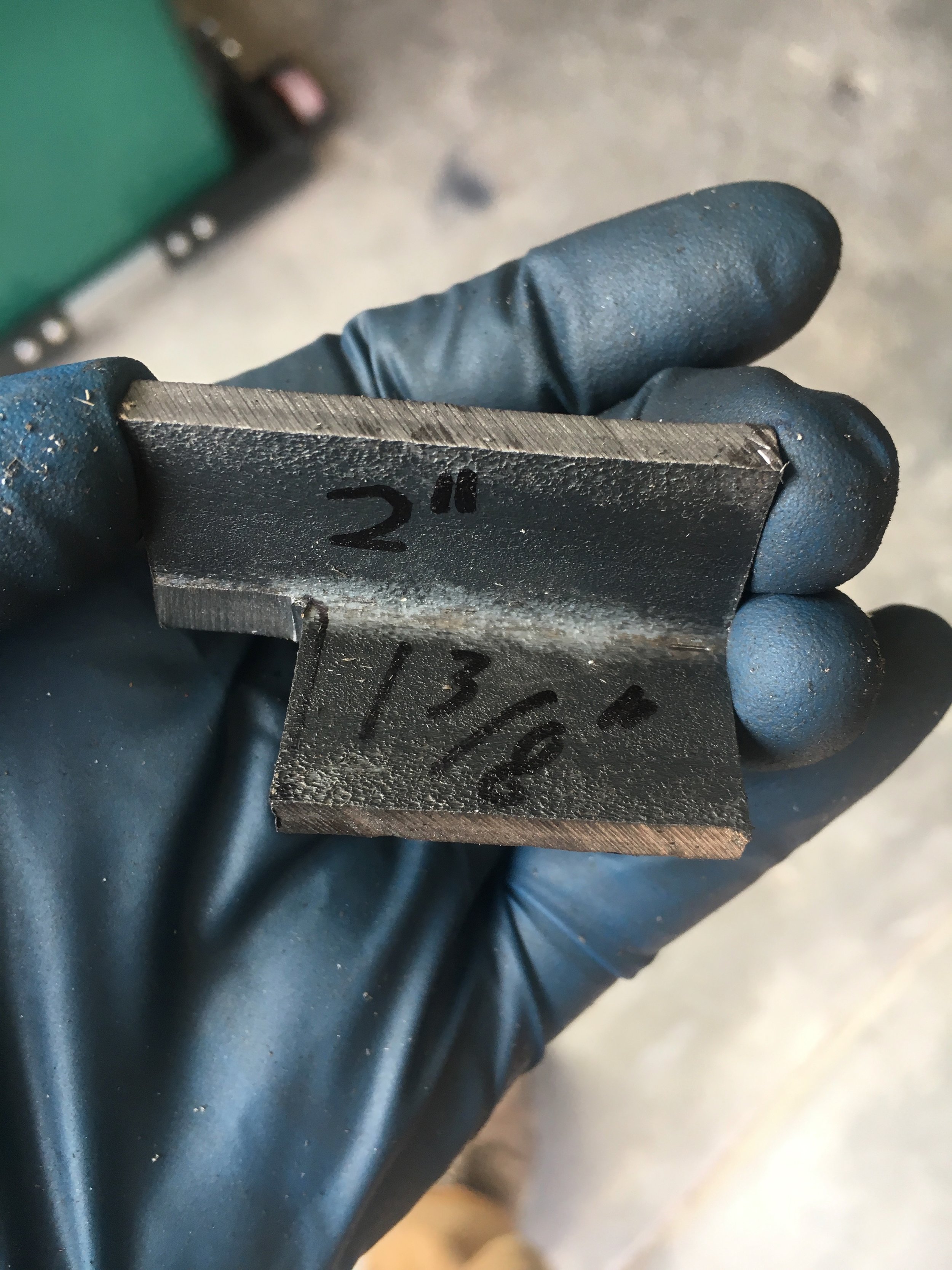
All the components are made from 3/16” thick mild steel. They are: (i) an inner bracket that replaces the OEM rear alternator or generator mount, made with 1-1/2” wide angle iron; (ii) a center trapezoid cut from 3” wide flat bar; and (iii) an outer bracket fashioned by cutting and drilling 2” wide angle iron.
Here are the three components of the rear mount laid out for welding (note that the anti-corrosion coating is sanded off to avoid contaminating the welds):

*Note for owners of right-hand drive cars: you may have to cut a small relief to allow the steering column to clear the rear mount, as shown in the following image. Doing so will not significantly weaken the rear mount, whose sole purpose is to support the blower in a vertical plane. Together, the blower and Creative Spridgets aluminum M45 manifold weigh just 19 lbs. or 8.6 kg:

STEP 1 - Cut the Center Trapezoid.
You should rely on the downloadable CAD drawings for the dimensions, but here are images showing how to mark and cut the part for the 65-degree angle that is a repeating theme in making the rear mount:
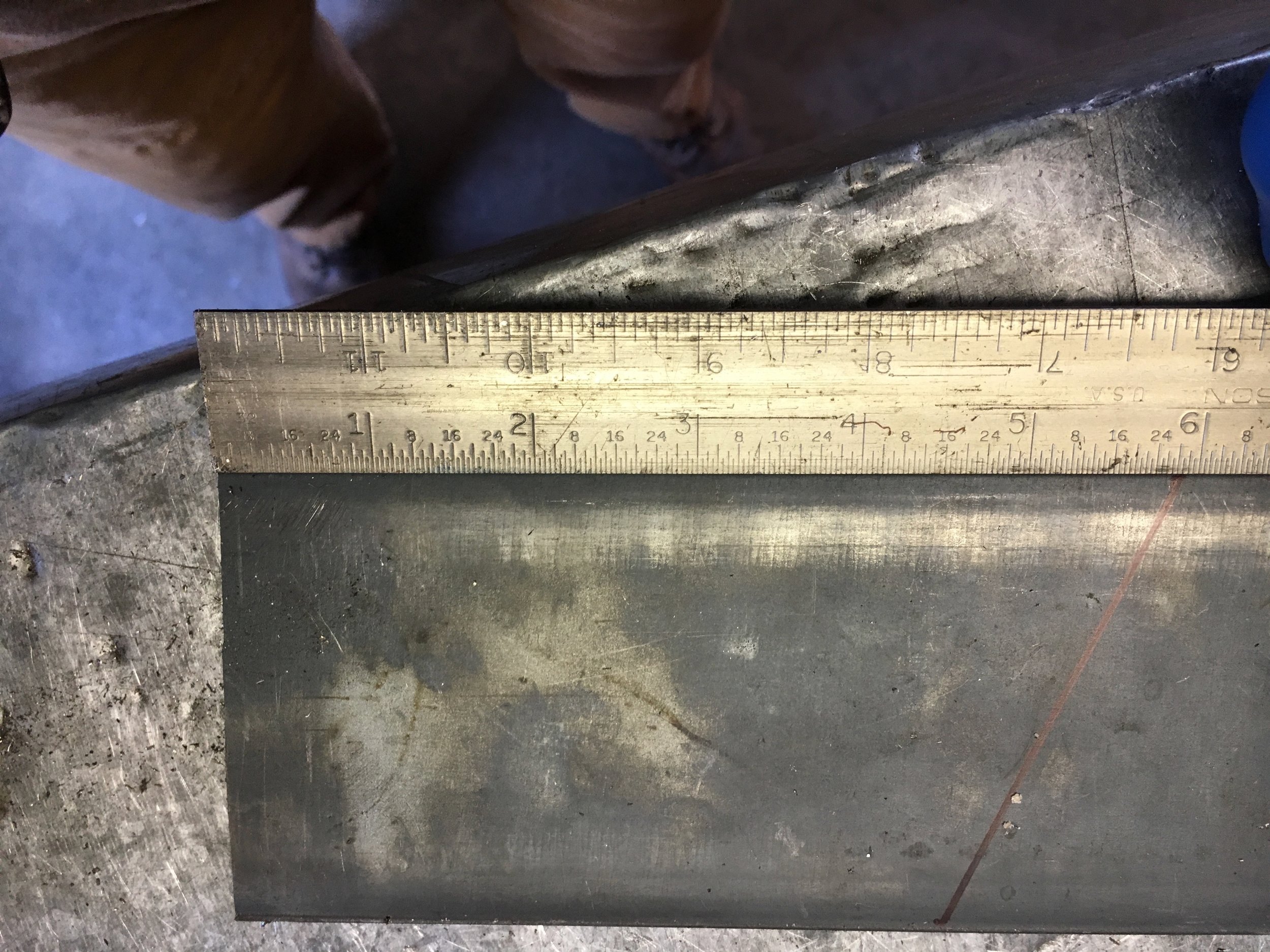
It is not critical that the mating edges be perfectly even, as the welds will fill in any small gouges, file or grinder dressing marks, etc.
What is important are three things: (i) the 5-15/16” measurement of the longest edge is a finished dimension; (ii) the angle that starts at the end of the longest side must be as close to 65 degrees as possible; and (iii) the short side must be precisely perpendicular to the two longer sides—that is, at 90 degrees to them.
The reason for taking care when measuring and cutting this otherwise simple component is that it establishes the outboard, third component’s relationship to the vertical plane of the engine block, and thereby determines the supercharger’s position in three-dimensional space. So, take your time when making this part.
STEP 2 - Fabricate the Inboard Bracket
The innermost component is designed to achieve three goals:
Goal number one: this bracket reproduces the layout of the slotted 5/16” holes for the bolts that affix the rear OEM generator mount to the block, and their relationship to the single hole that will receive the 8-1/2” long, 5/16-18 bolt which supports both the CS121D internally cooled alternator used in this conversion and the idler pulley:
Goal number two: the outboard side of this part provides a flat mating surface for the first butt weld you will complete:

Goal number three: the design provides more metal than the original mount to allow for longer slots, thus enabling greater fore-aft adjustment of the blower:

First, cut an approximately 3-3/4” long piece of 1-1/2” wide angle iron (the piece in these photos was a little short, which took away some of the ‘forgiveness’ of he design) and drill the single hole for the alternator pivot bolt.
You should take all longitudinal measurements for the holes in this part from the same end of the stock; lateral measurements are from the flat or outside edge of the angle iron—i.e., not from the middle of the radius formed by the angle iron’s extrusion:
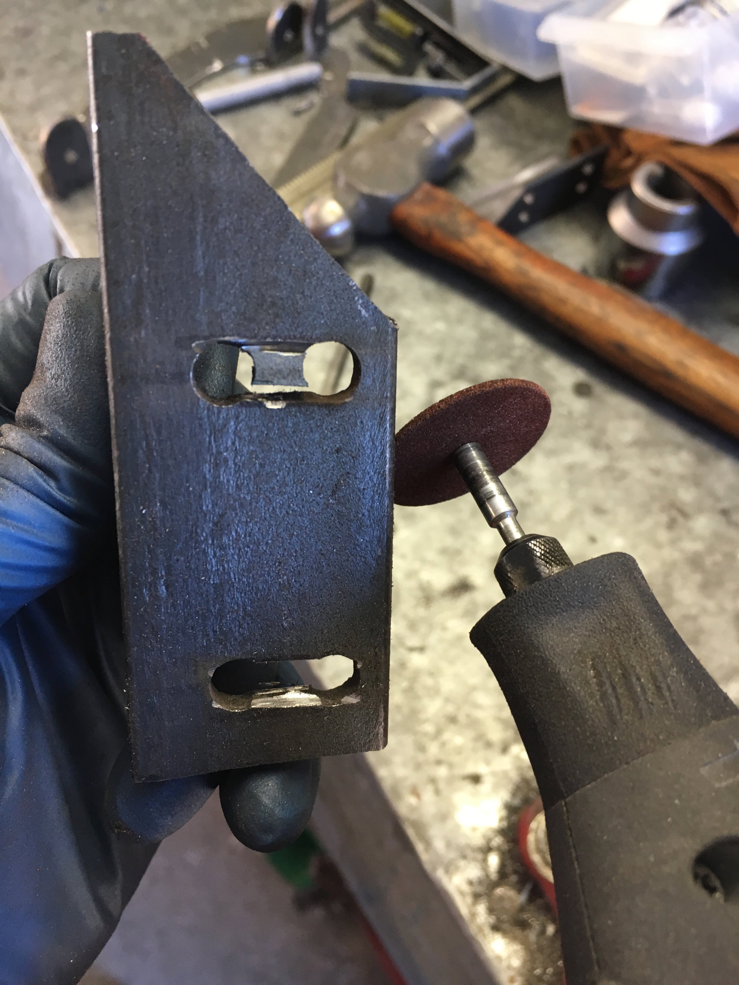
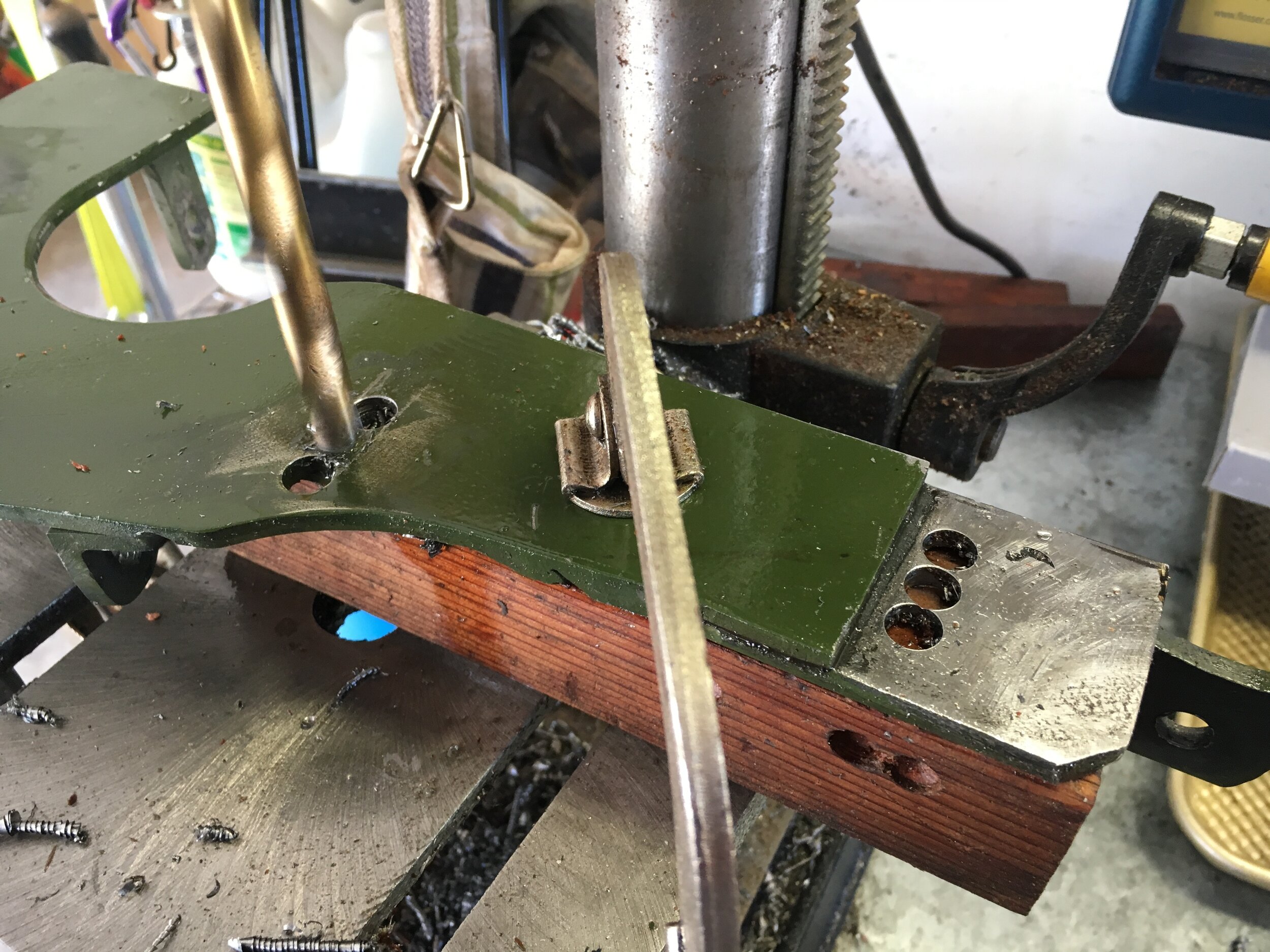
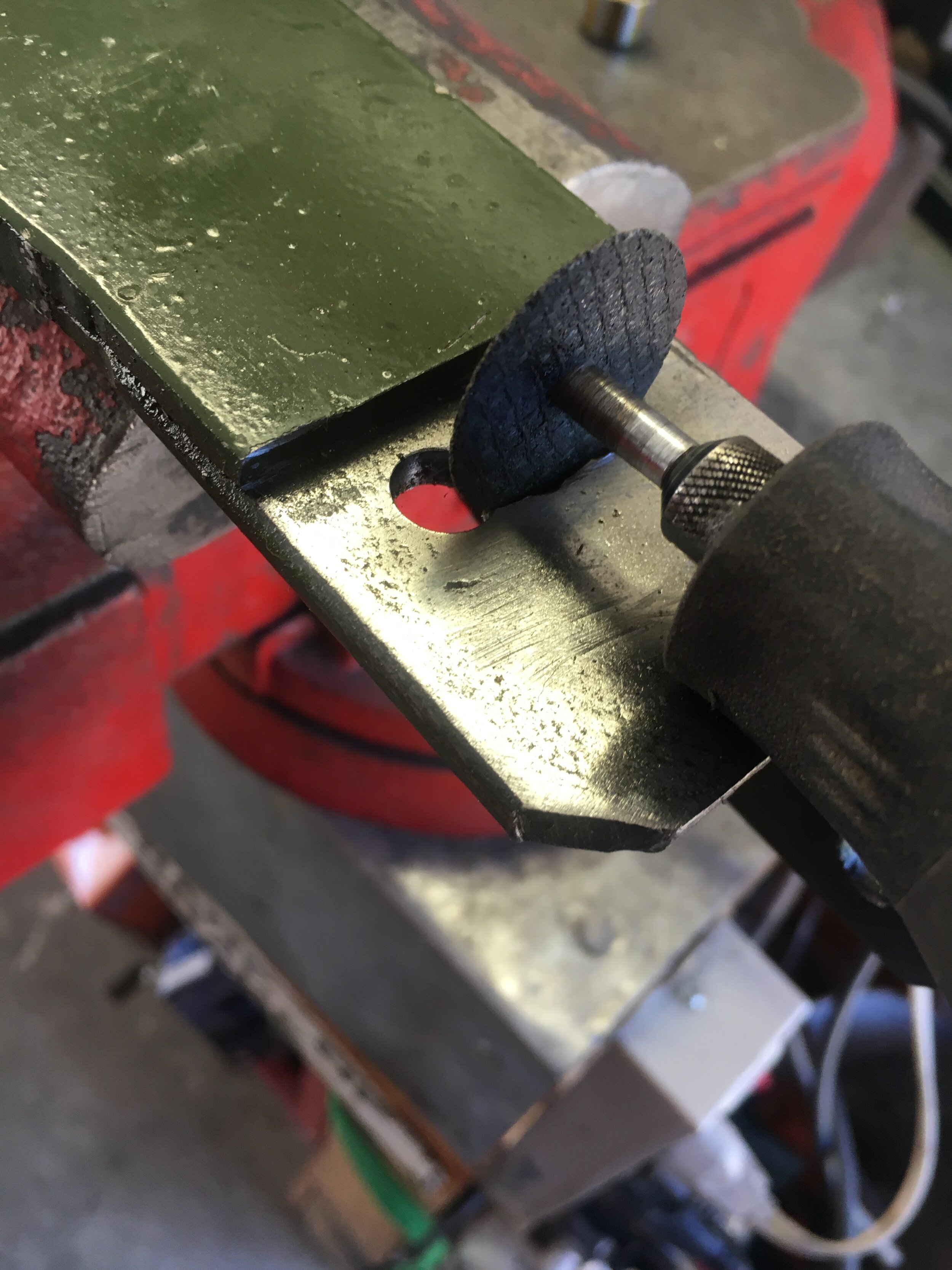
Second, drill and slot the oval holes that provide the gross, initial fore-aft adjustment of the supercharger.
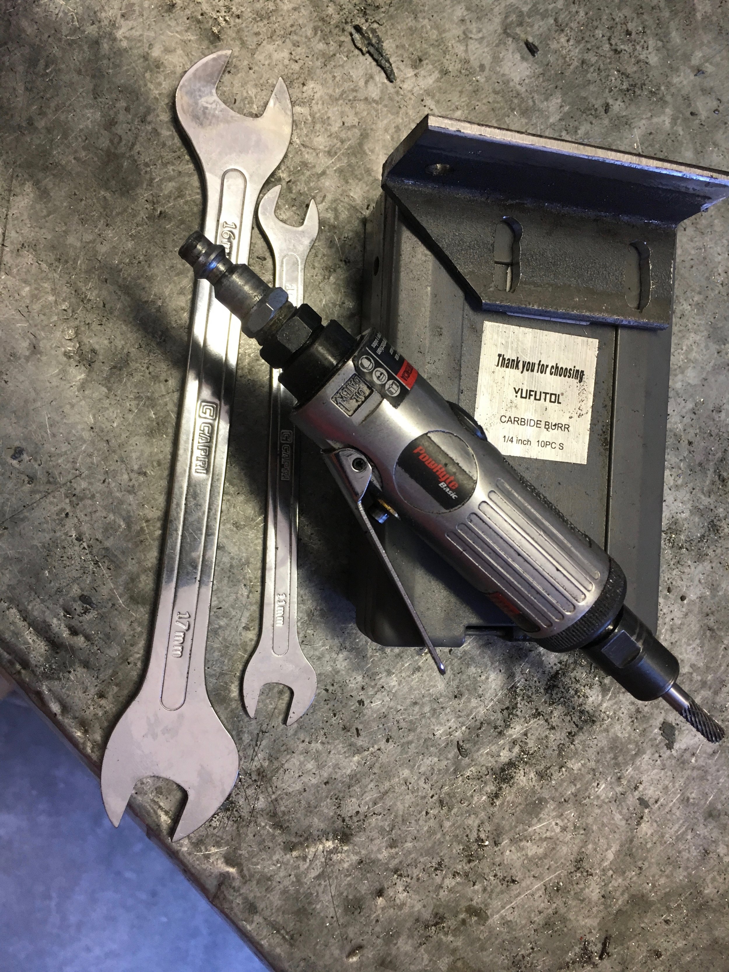
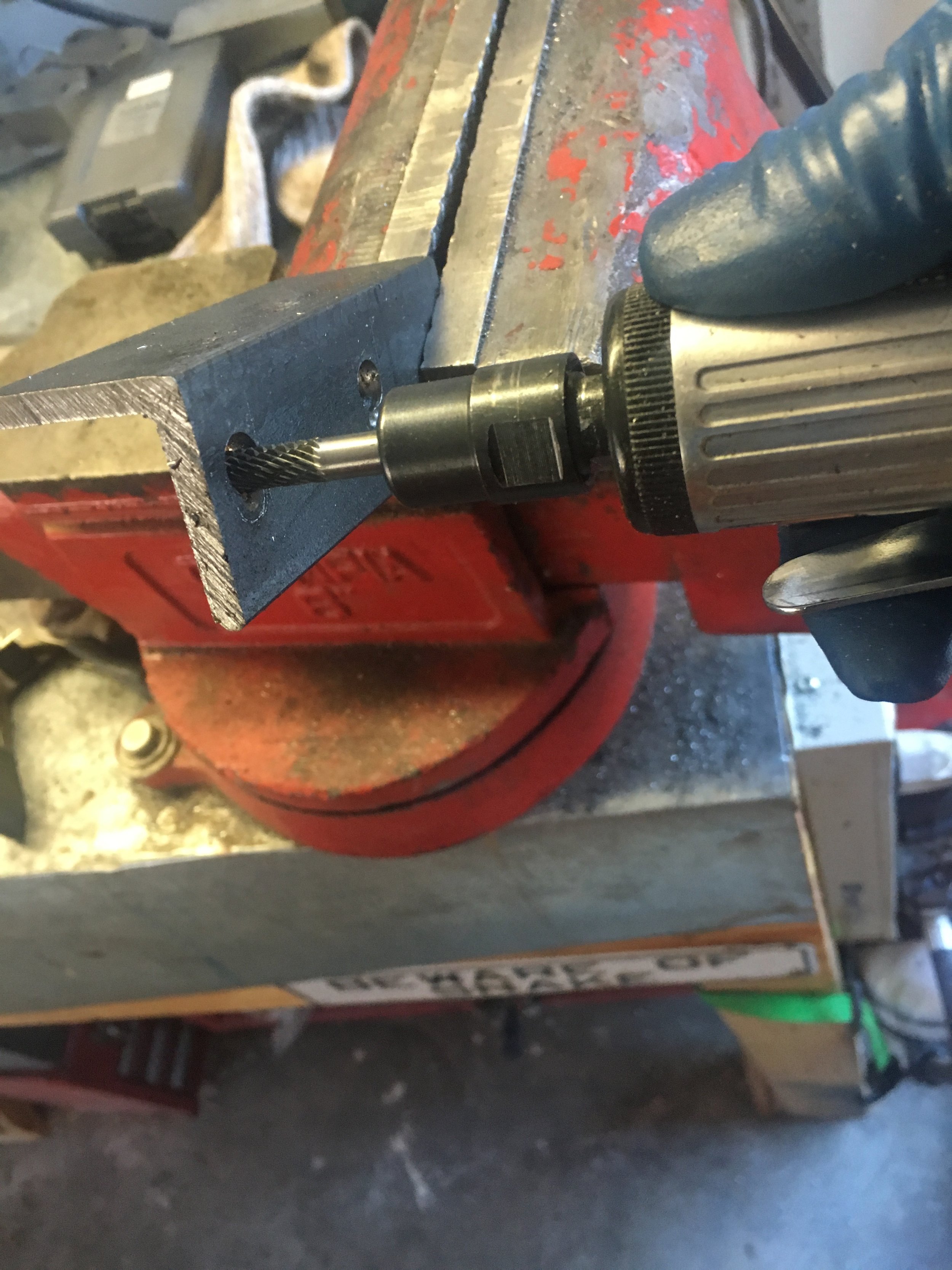
The easiest method is to drill two holes and then connect them with a Dremel or small cutoff wheel mounted in a drill motor. You can use a small file to smooth the borders of the slots, but a quicker method is shown in the third image—an inexpensive pneumatic die grinder ($13.00 on the internet) and a cheap set of carbide burrs.
(We found the Capri forged, thin-body wrenches in the third photo far superior to the soft metal wrenches that came with the grinder, but they cost more than the grinder and bits combined.)
Third, if you wish, cut the 45-degree angle to make more room for your fingers when checking the oil dipstick and working with the oil filter assembly.
Be sure to break all sharp edges.
STEP 3 - Fabricate the Outer Bracket
Fashioning the third component out of 2” wide, 3/16” thick angle iron is not technically difficult; it is just time-consuming. Be patient, go slowly, and you will be rewarded with an elegant and durable rear mount.
First, cut an 11.5” long piece of angle iron. It is important to end up with at least that much steel; 11.75” is probably a better starting place, as it’s possible to cut the ends a little crooked which will require re-squaring. That process will shave off overall length.
If you look closely at this image, the stock was a hair under 11.5” and this required a higher level of precision in making the part, as you will see later on.

Second, mark one corner to indicate the point from which all of the coming longitudinal measurements are taken. Note that there are only two, diametrically opposed corners of the stock that you can select to make this mark:

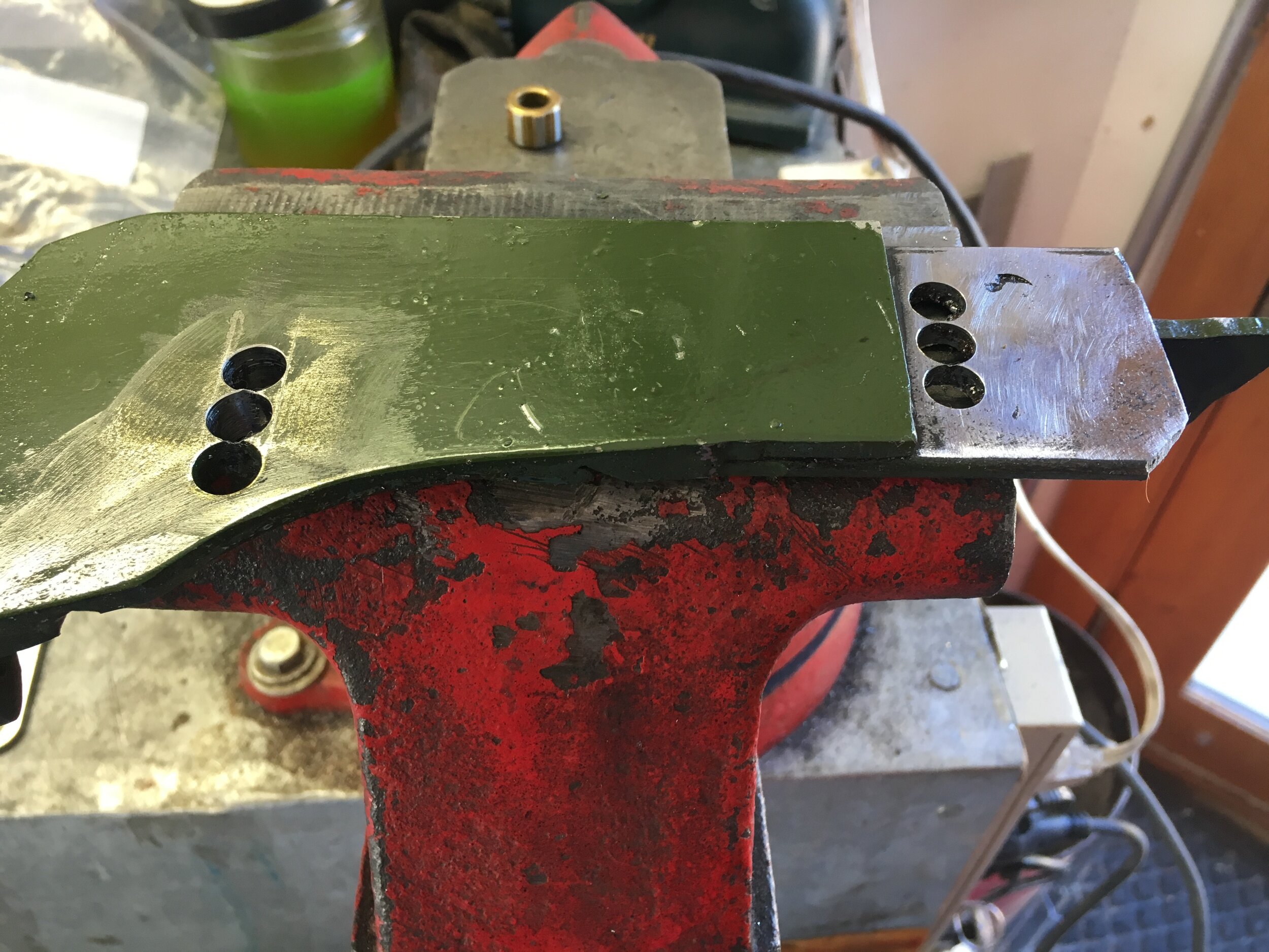
Here are the measurements to locate the two, asymmetrical holes that will correspond with the supercharger’s offset rear mounting tabs:

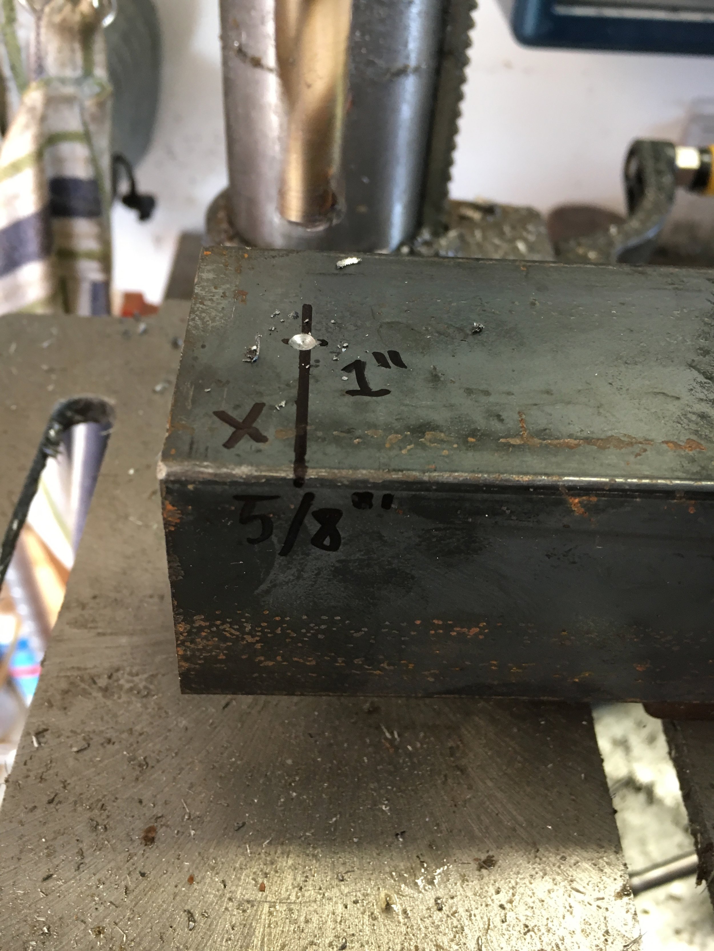
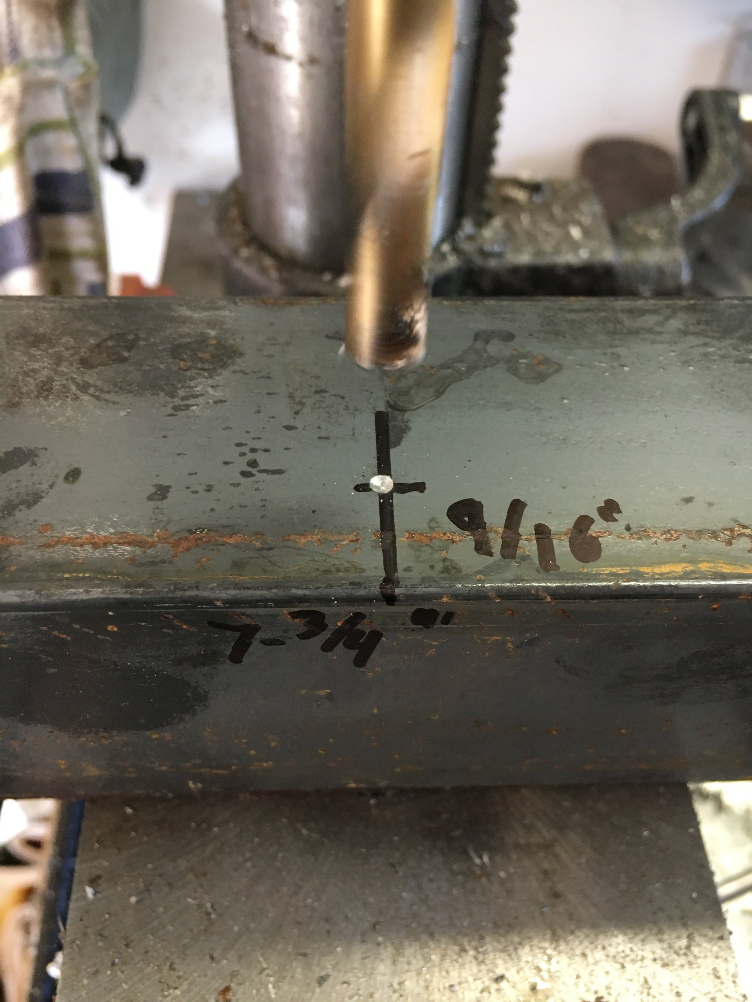
Third, drill the 5/16” holes per your measurements. Although a drill press is shown here (the stock is resting on a piece of wood, with both pieces clamped to the table), a hand drill is fine. Just make sure in any event that you use plenty of oil, adding it often during the process, and let the bit work at a natural pace.
Fourth, measure and mark the two inner cuts that function to: (i) form the mounting tabs that will bolt onto the blower’s rear mounting ears; (ii) create the relief for the rotor chamber to nestle into the rear mount; and (iii) begin creating the mating edge for welding this part to the center trapezoid:


Fifth, make the cuts, using either an electric band saw or hack saw (a plasma cutter is not recommended for this operation, as the jagged edges will reduce the width of the tabs), making sure not to slice through the other part of the angle iron. Stop in time to leave roughly the thickness of the stock, or 3/16”:

Sixth, carry the lines formed by the cuts you have just made onto the other side of the angle iron, and then mark the radii and bottom of the relief for the supercharger’s rotor chamber.
It is not critical that the relief have rounded ends. Doing so merely results in a more aesthetically pleasing mount that follows the contours of the supercharger’s ribbed rotor chamber:


Seventh, cut the end farthest from your initial index mark to form a mating edge which will be welded to the middle trapezoid.
The width of the inboard mounting tab thus created is not critical; the only critical dimension resulting from cutting its profile is that you must leave 3.0” at the end of the part to mate with the 90-degree, outboard end of the middle trapezoid you made previously:


Eighth, cut and shape the relief for the rotor chamber, and also cut the angles beneath it, thereby forming the gross contours of the bracket.
The angles forming the outboard side of the component (the bottom in the next picture) may default to 65 degrees to create visual harmony with other components, but this is entirely up to you.

Ninth, round off the mounting ears. The quickest method is to cut 45-degree angles with a saw and then grind the steel to form a graceful curve.

Tenth, before breaking the edges and scuffing off the anti-corrosion finish to prepare for welding, slot the fore-aft, fine-adjustment holes in the mounting ears.
Refer to the CAD drawings for the location of the holes that form the slots, drill the holes, and then connect them with a Dremel or small cut-off wheel in a drill motor:


STEP 4 - Weld the Components Together
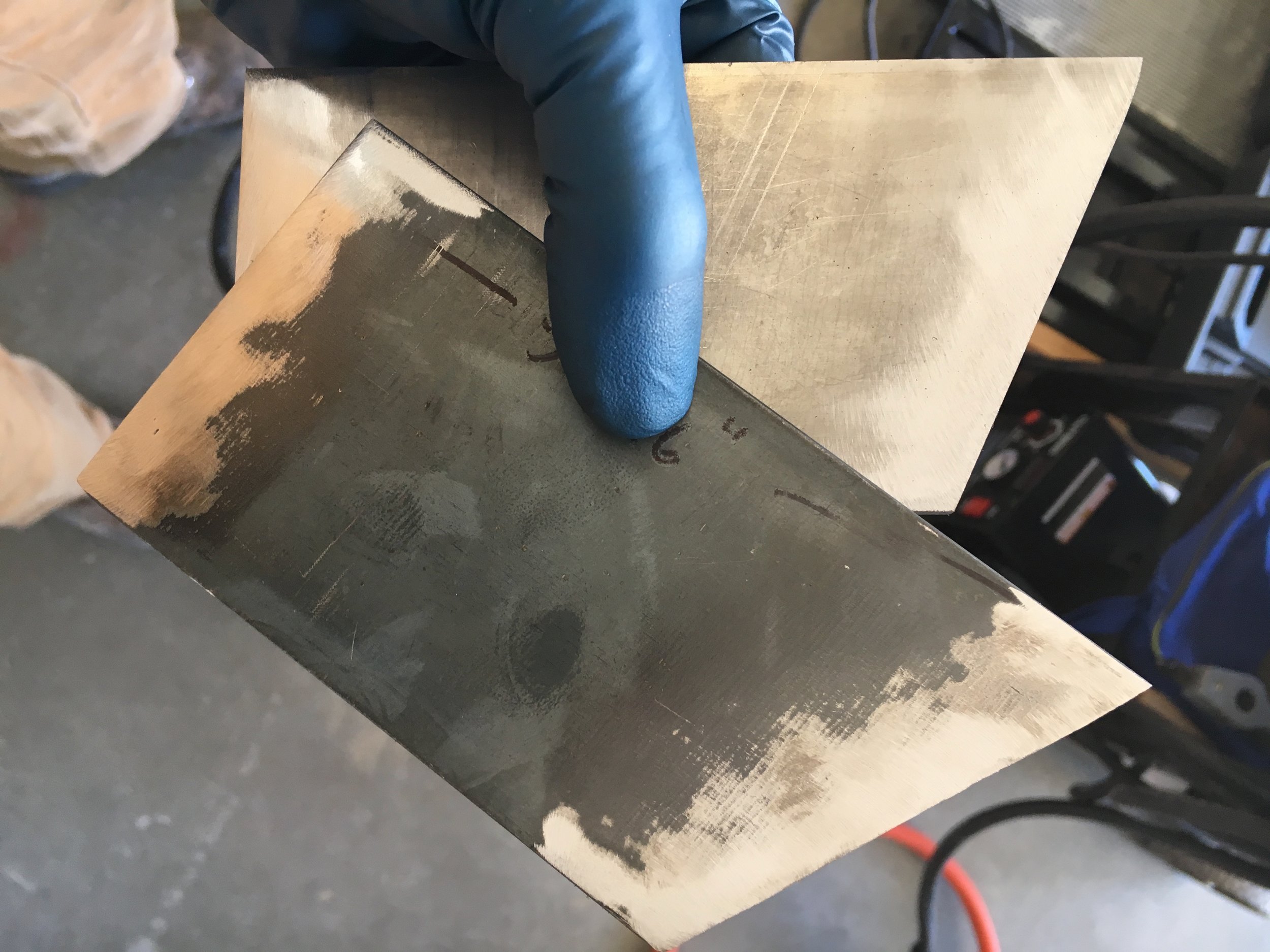
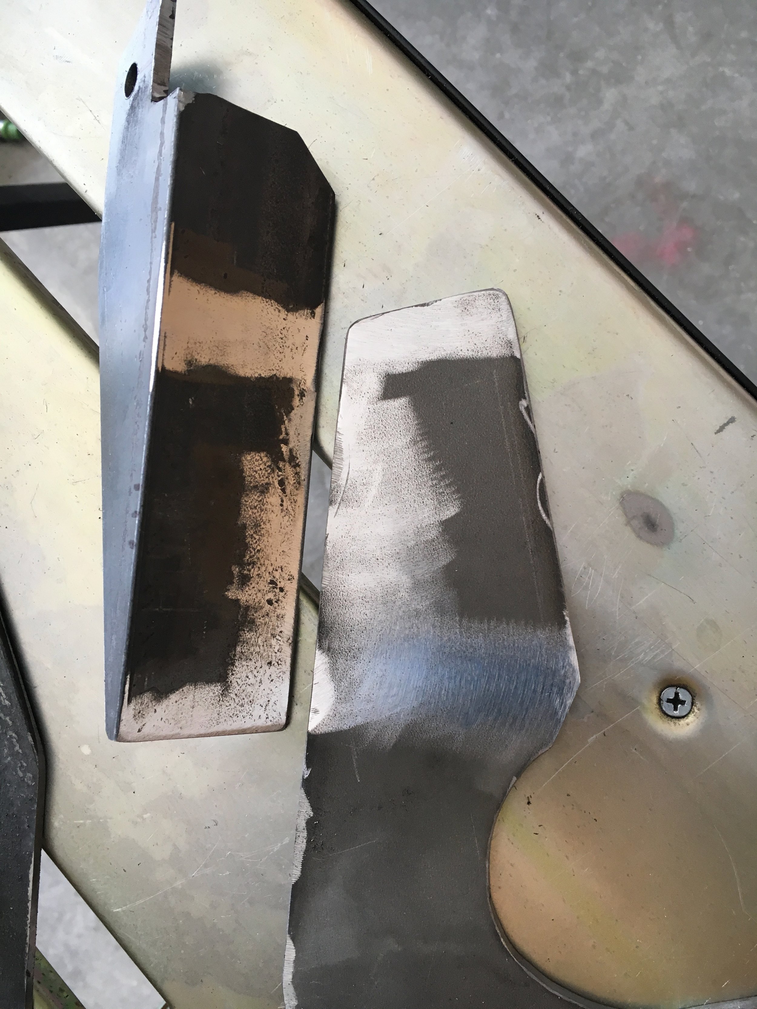
First, sand off the protective coating near the mating edges (on both sides and all adjacent edges), clean the steel to avoid contaminating the welds (brake cleaner works well for this), and jig the parts up on a flat surface for welding:

Second, weld one side of both joints and let the part cool a little before proceeding. Do not dip the part in water, as you want to retain much of the heat for the next welds.

Note the discoloration along the full length of the initial welds in the above photo. This indicates good penetration and a durable weld.
Third, weld the other sides of the joints:

Fourth, after breaking all sharp edges, test fit the mount on the engine block.
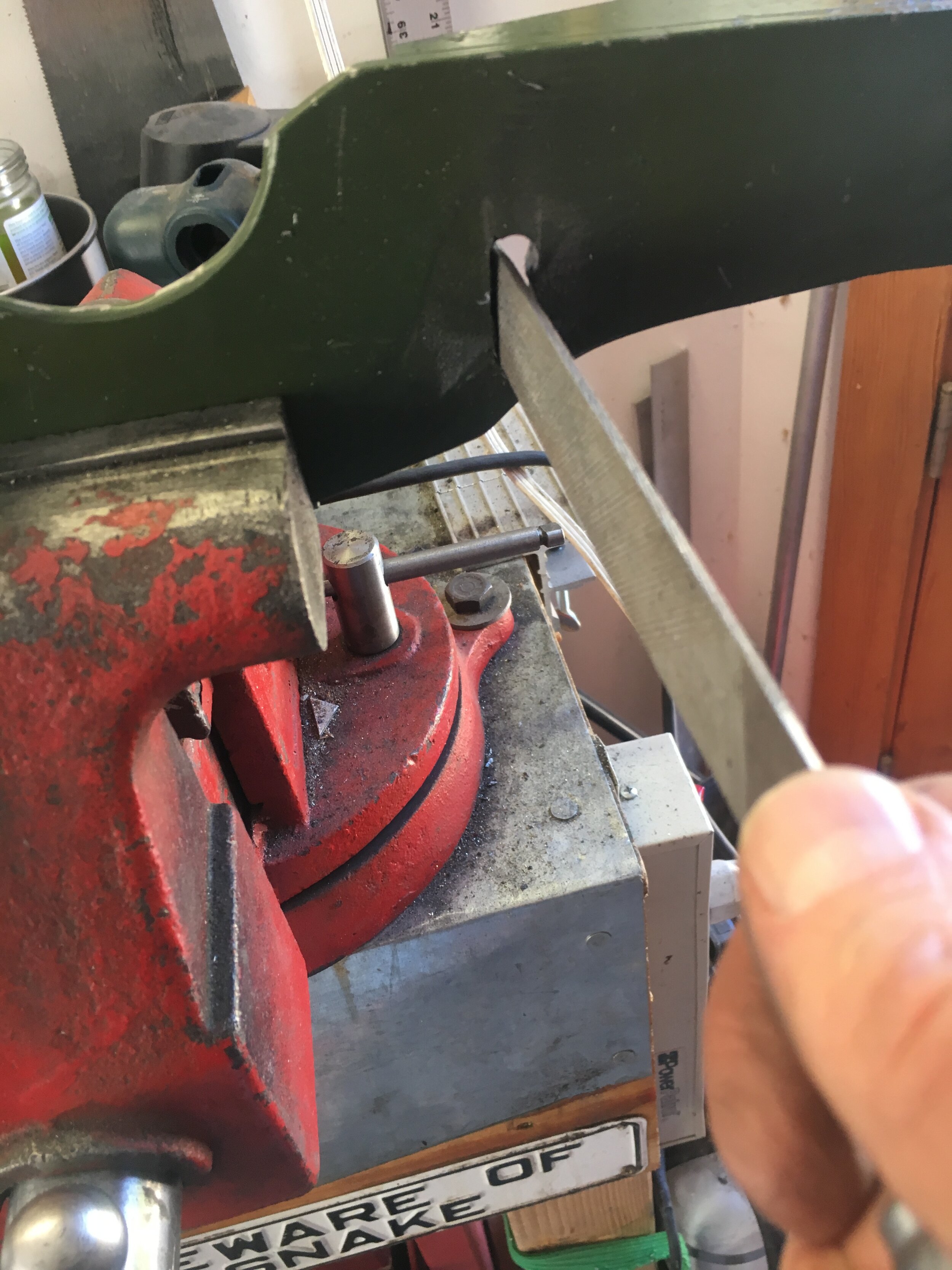
The mount should extend outward at 90 degrees from the plane formed by the line where the cylinder head joins the block. If it is not perpendicular to the head, readjust the mount by grabbing it in a vise as shown below:

We found it easiest to apply even pressure by using two big crescent (adjustable) wrenches or one paired with a medium-sized monkey (pipe fitting) wrench.
Finally, degrease the mount and finish with your choice of high-temperature engine paint. Once the paint has dried, you may bolt the mount to the block—positioning the original 5/16-24 bolts in the center of the fore-aft adjustment slots and installing your generator or alternator as usual. You may now continue running naturally aspirated while focusing on the front mount.
SECTION B: The Front Mount
Review the free downloadable CAD diagrams to familiarize yourself with the design of the front mount.
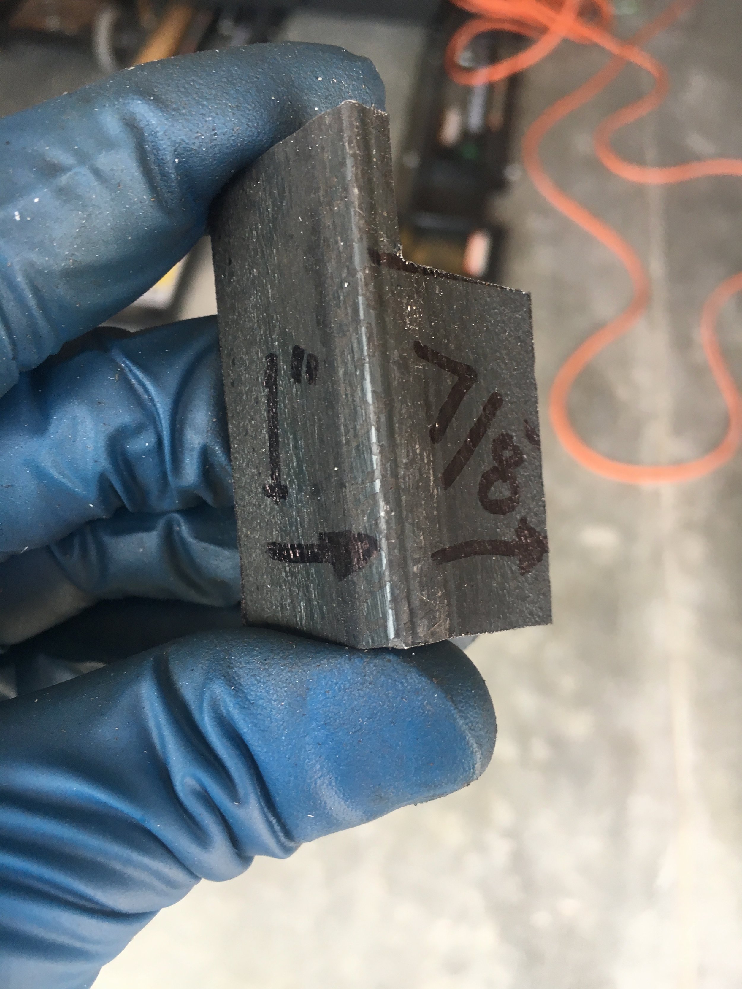
The front mount is easier to make than the rear mount, as it is composed of just two components: a ‘J’-shaped, vertically oriented piece of 3/16” thick, 6” wide mild steel that encircles the supercharger’s snout and will receive its front mounting bolts; and another simple shape fashioned from 3/16” thick, 2” wide angle iron. There are also two small mounting tabs welded to the ‘J’-shaped outboard piece with the supercharger in place and aligned, as shown at the end of this section.
Below is a photo of the ‘J’-shaped, outboard component laid out on the mild steel stock. Both of the long angles are 65 degrees; the short 7/8” angle should be roughly perpendicular to the 4-1/2” side to the left of this image, but that is entirely arbitrary; it could just as well parallel the 6-3/4” longest angle above it in this photo (and below it when the part is right-side-up). It could also be a curve rather than a flat ray. This choice is purely aesthetic.
Indeed, the only critical dimensions on this part are: (i) its height—which provides enough room to attach the snout’s mounting tabs and the support strut that makes the alternator a stressed member and produces an extremely rigid mounting system; and (ii) its overall length—which allows sufficient inboard/outboard adjustment when jigging the part up for welding, as we will see shortly:

Remember to defer to dimensions on the free, downloadable diagrams available on our purchase page.
STEP 1 - Cut the Outboard Component
This part may be cut with a plasma cutter to save time, in which case a large socket, lid from a jar, or other appropriate shape may be clamped to the steel to guide the torch and produce the circular relief for the blower’s snout.
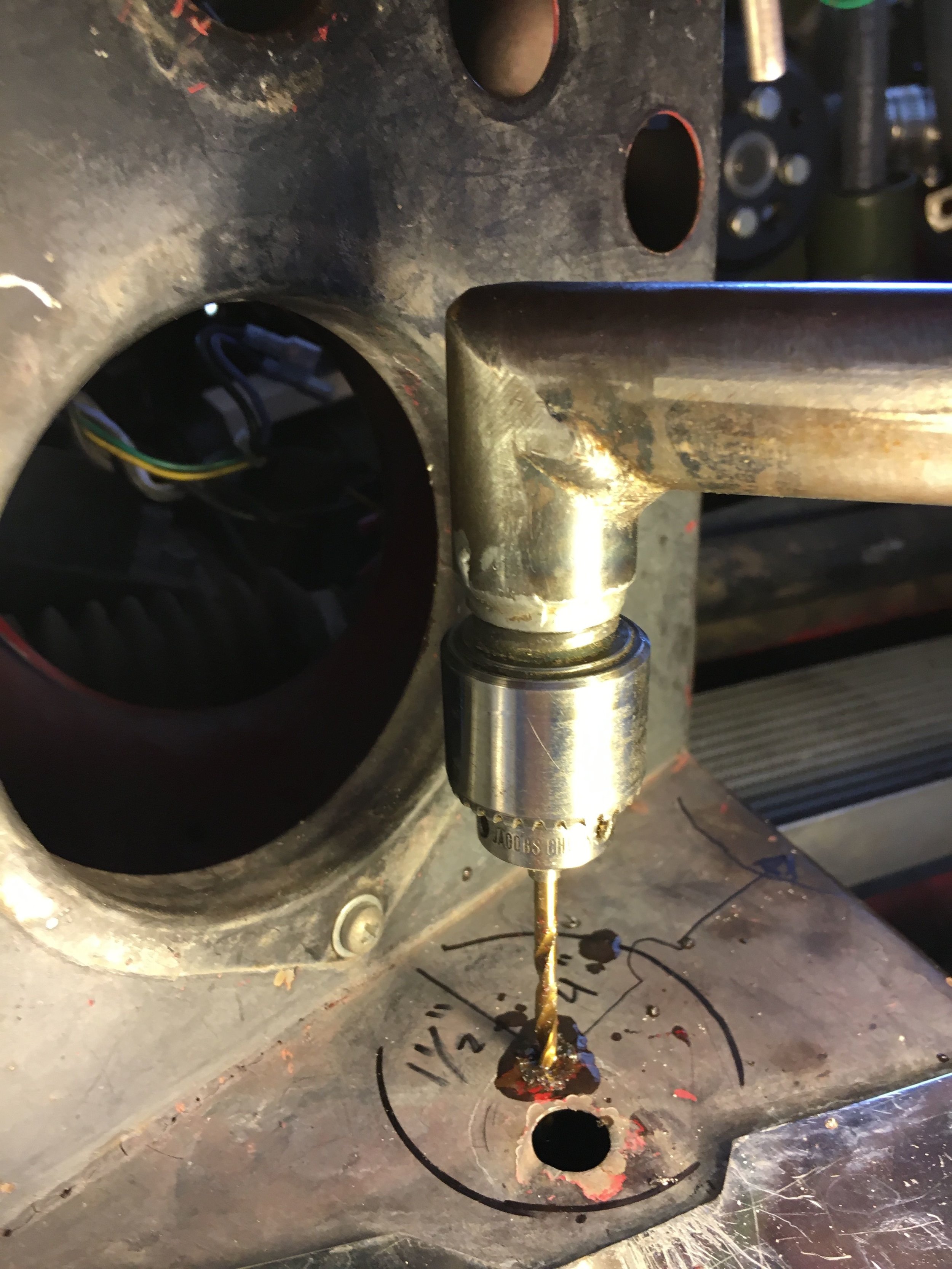
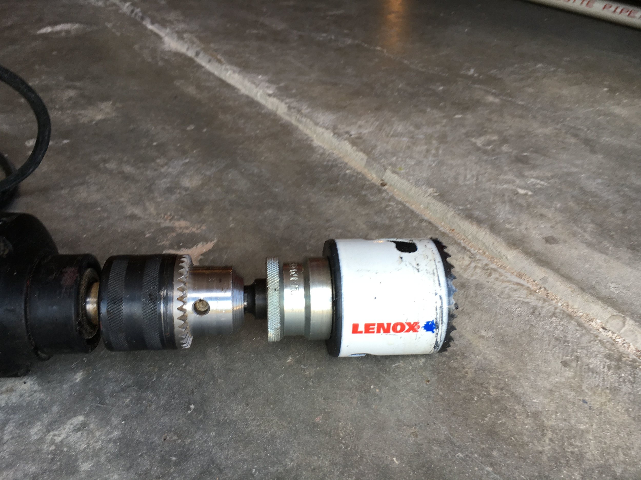
Alternatively, a bimetal hole saw will produce a very clean radius—taking your time and applying liberal amounts of oil—though the blade may not survive to make more than one part:

The remainder of the outer profile can be easily cut with a plasma cutter, a hand-held electric band saw, a ‘saws-all’ with a bimetal blade, a jig saw with an appropriate blade, or more laboriously with a hack saw and plenty of elbow grease.
STEP 2 - Fabricate the Inboard Component
The inboard component is fashioned from a length of angle iron, as shown in the next image, and is simple to make. Indeed, the only critical dimensions relate to the 3/8” hole which slides onto the last cylinder head stud in the torquing sequence.
*Note: the photos in this section show a 1275 head. The 948 and 1098 heads require a slightly different shape for the portion that is drilled to receive the cylinder head stud, due to the reduced space between the valve cover and thermostat well. We will add photos for the smaller engines shortly.
First, drill the 3/8” hole that receives the cylinder head stud.
In the below photo, the 1-7/16” dimension locates the hole’s center from the flat, forward-facing side of the 2” wide angle iron (i.e., not from the radius formed by the angle’s extrusion). If this measurement is off slightly, the part will still be viable but its aft side—the top in this photo—may contact the valve cover and require relieving with a file or grinder. As always, defer for dimensions to the free downloadable diagrams available on our purchase page.

Second, make the two cuts that form the notch forward of the hole (downward in the above picture) for the cylinder head stud.
The 1/2” dimension locates the hole in an inboard/outboard dimension—to the right and left in the above photo—as measured from the cut made 90 degrees or perpendicular to the long axis of the part. In the above photo, the dotted line carries the plane of this cut across the top of the part for measuring purposes, as the author inadvertently made a gouge when making the lateral cut just forward of the hole (downward in this picture) with a hand-held electric band saw.
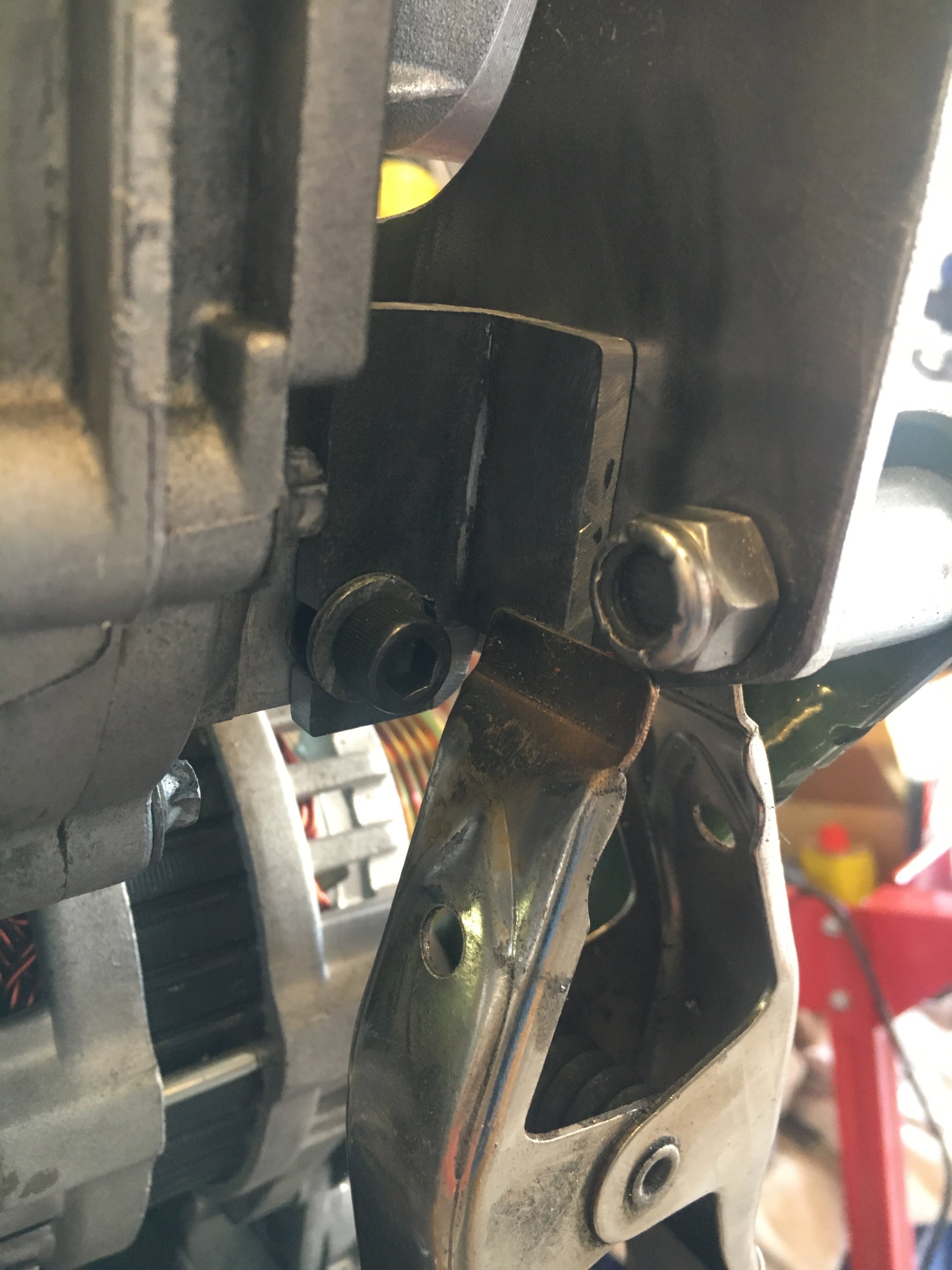
This error did not affect the part’s viability. But the longitudinal relationship (left-right in the above picture, or perpendicular to the engine’s long axis) between the hole’s center and the cut running down the front, vertical edge of the part is important, because that edge rests against the side of the cylinder head, thus creating a cantilever, as shown below:

Third, in the above and following photos note that there is a 45-degree angle at the bottom of the vertical angle resting against the head. Cutting this small angle provides relief for the protruding portion of the casting surrounding the hole for the temperature sensor:

Fourth, note that the part being fabricated above (first of the last two photos) features a profile along the edge adjacent to the thermostat housing that matches its contours. This is fine if you have a late model cross-flow radiator, as the housing aims toward the left-hand side of the car.
However, if you have a down-flow, early radiator or a VW Rabbit radiator conversion (like the 1967 MG Midget pictured in these instructions), you will need a Creative Spridgets combination thermostat housing spacer and GM-style temp sensor mount pictured below and available here.

*Note: the above photo shows an OEM longer head bolt installed in place of the short bolt, together with a 3/8” I.D. x 1” long spacer. However, it is possible to retain the short bolt if you use an ARP stud and/or an ARP-style, shorter nut.
The spacer has a square outer profile, so the relief for the OEM thermostat housing must be moved back toward the 3/8” hole for the head bolt and made more square, as shown in the earlier picture enlarged here to emphasize the area in question:
Fifth, when finishing the vertical edge that rests against the side of the head adjacent to the thermostat housing, use a square to make sure the part will rotate on the head bolt far enough so the part protrudes at 90 degrees from the head’s long axis.
Here is an image showing a part that needs just a little more material shaved off to allow the part to pivot forward sufficiently:

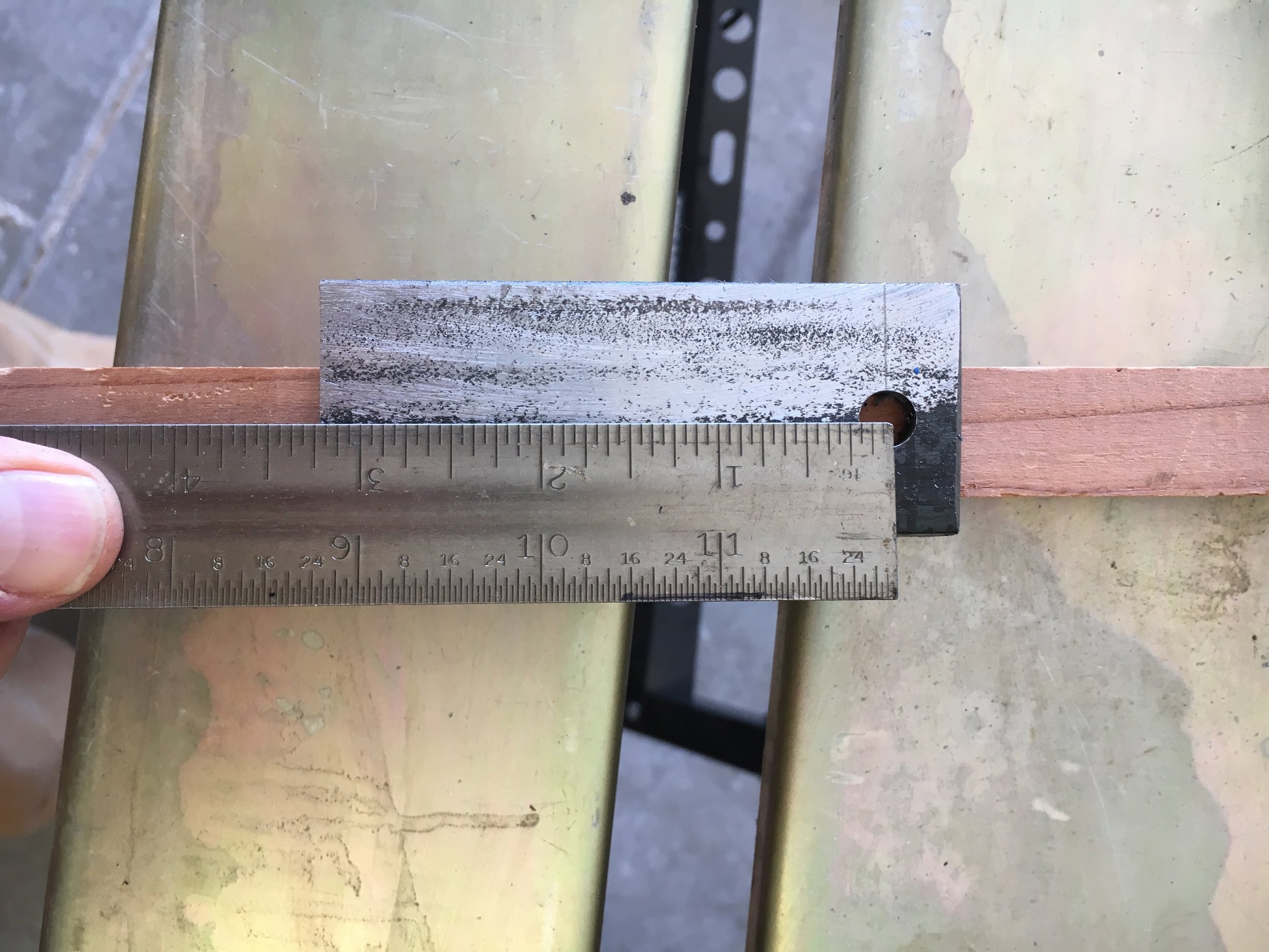
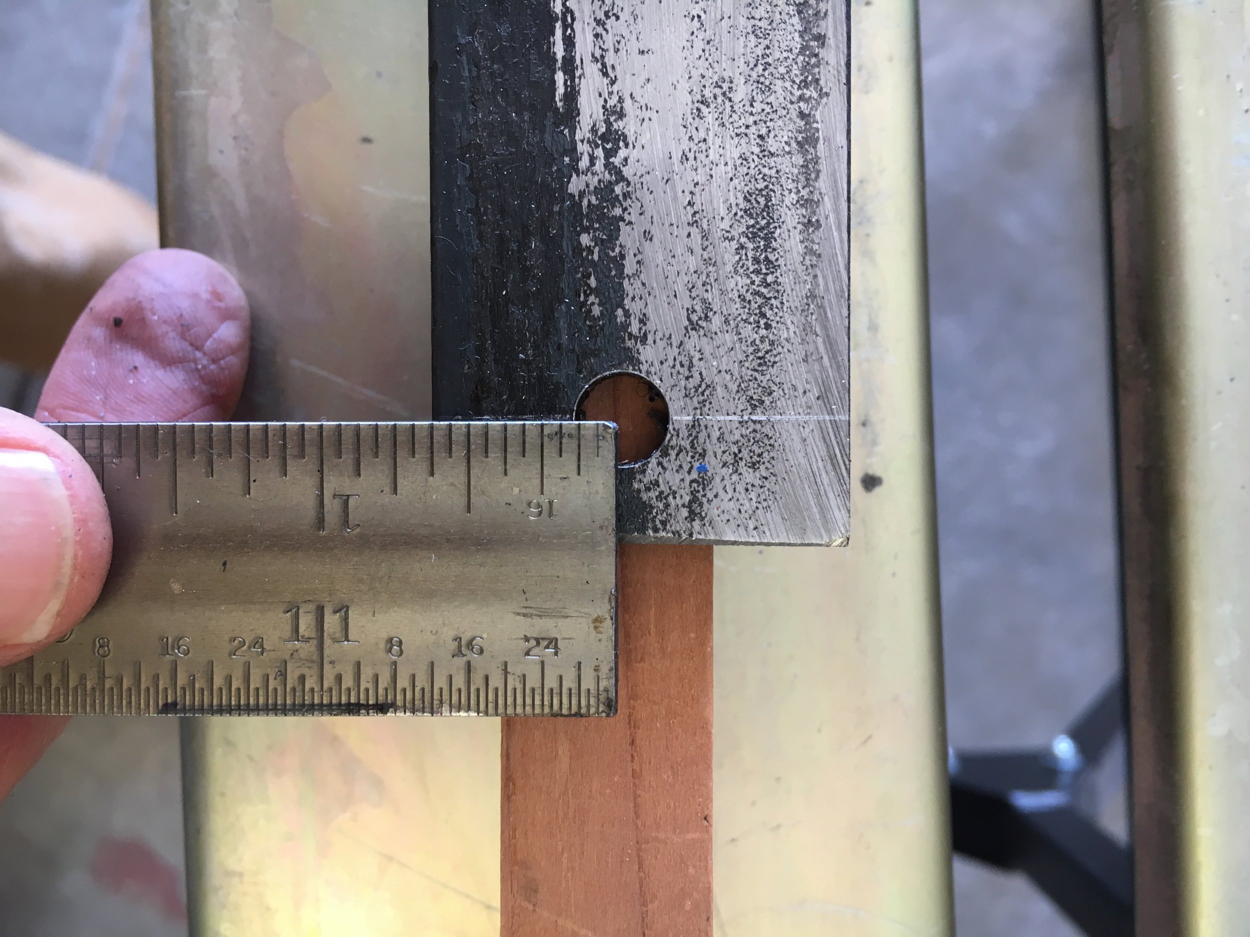
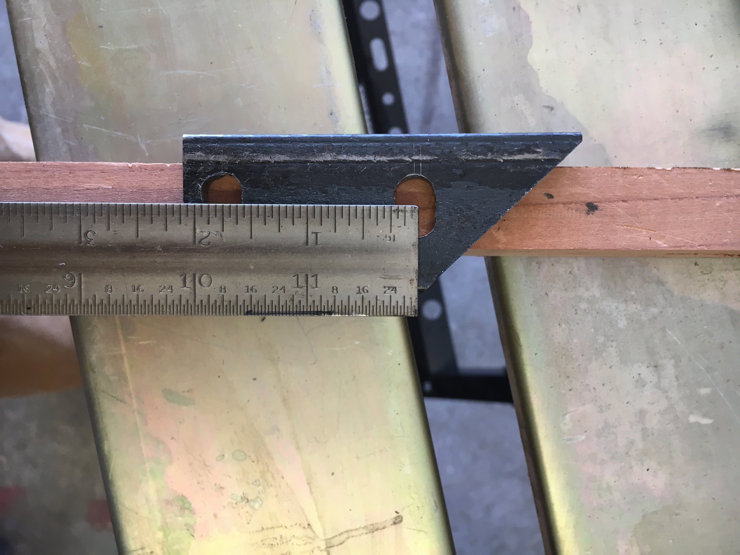
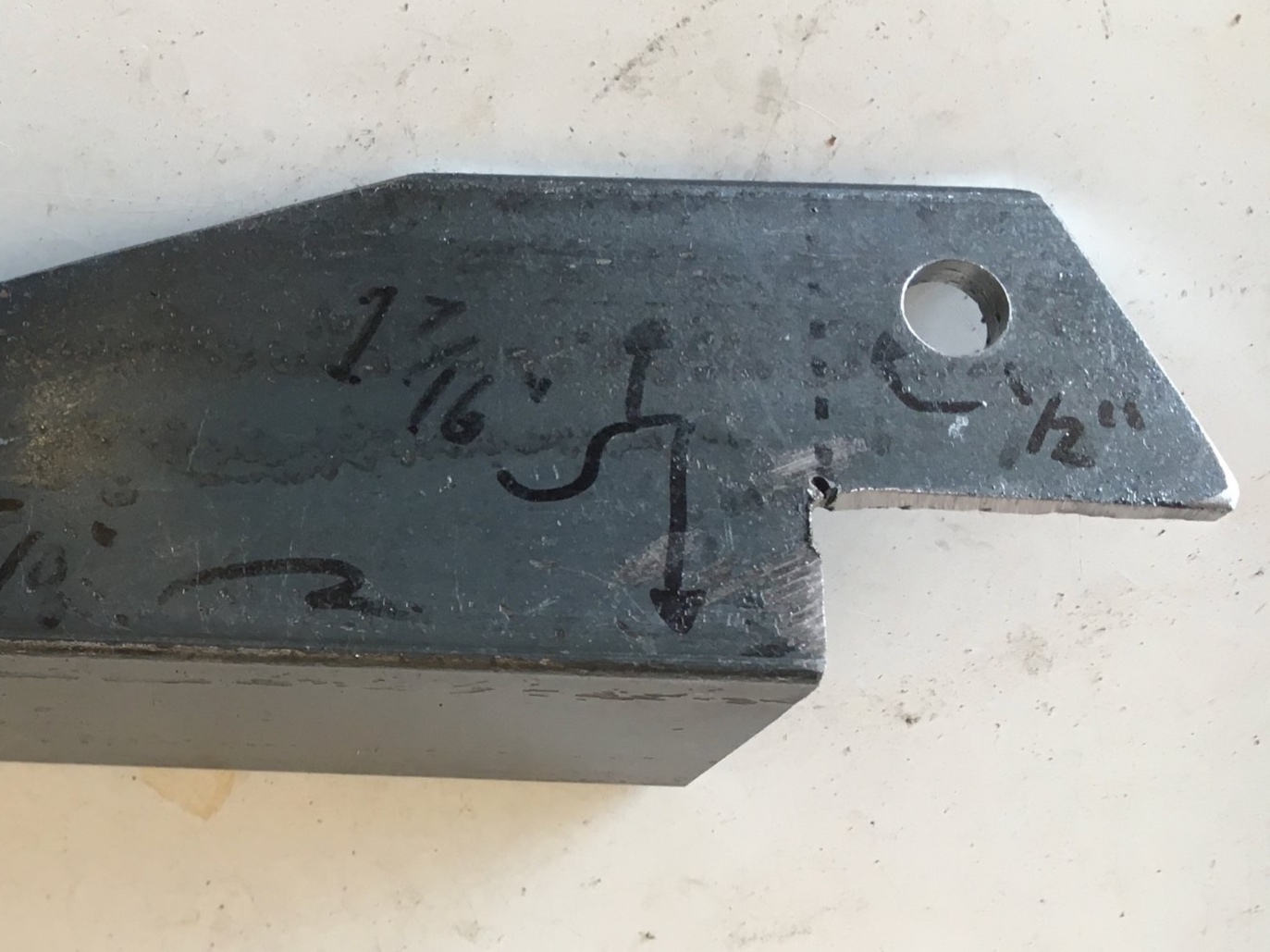
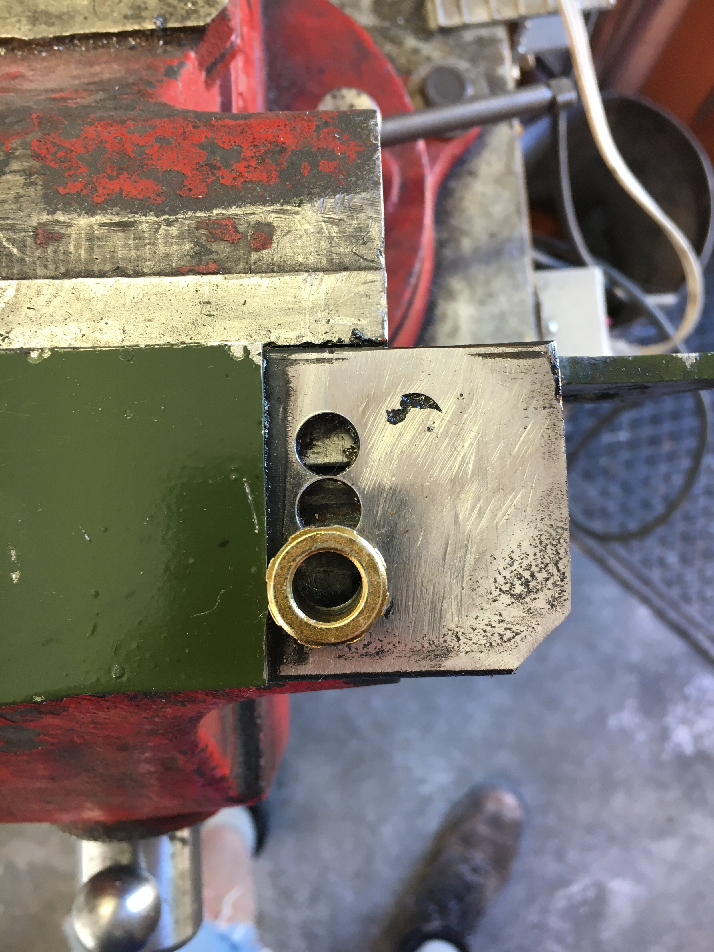
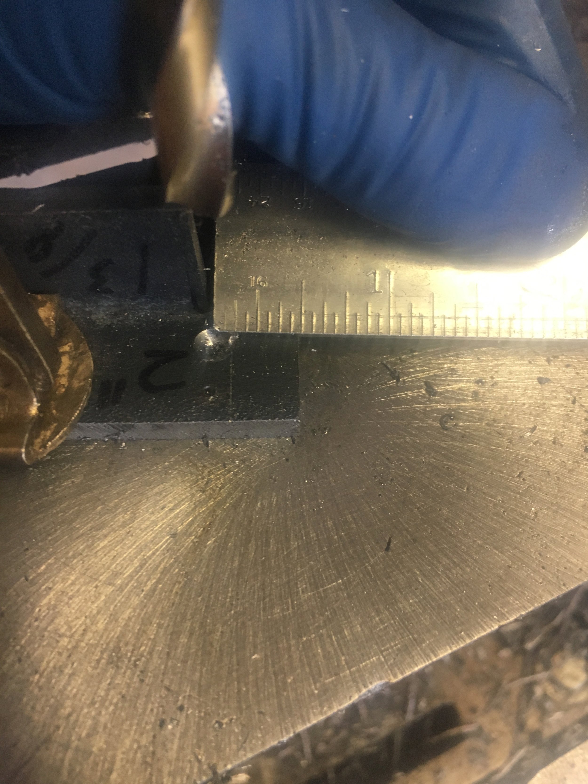
Sixth, as shown in the following image, place the two components in a vise (or clamp them together), align their top edges, and mark the center of the 3/8” cylinder head stud hole and the center of the large semi-circular relief for the blower’s snout.
Defer to the downloadable CAD diagram for the appropriate measurement, then measure the distance between the centers using a carpenter’s square and small adjustable or fixed square or triangle:


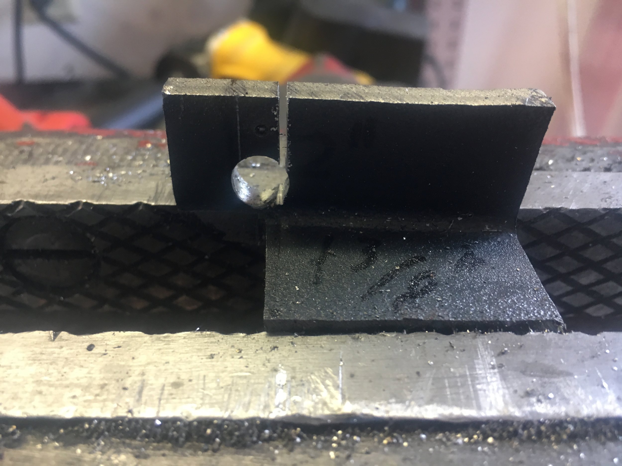
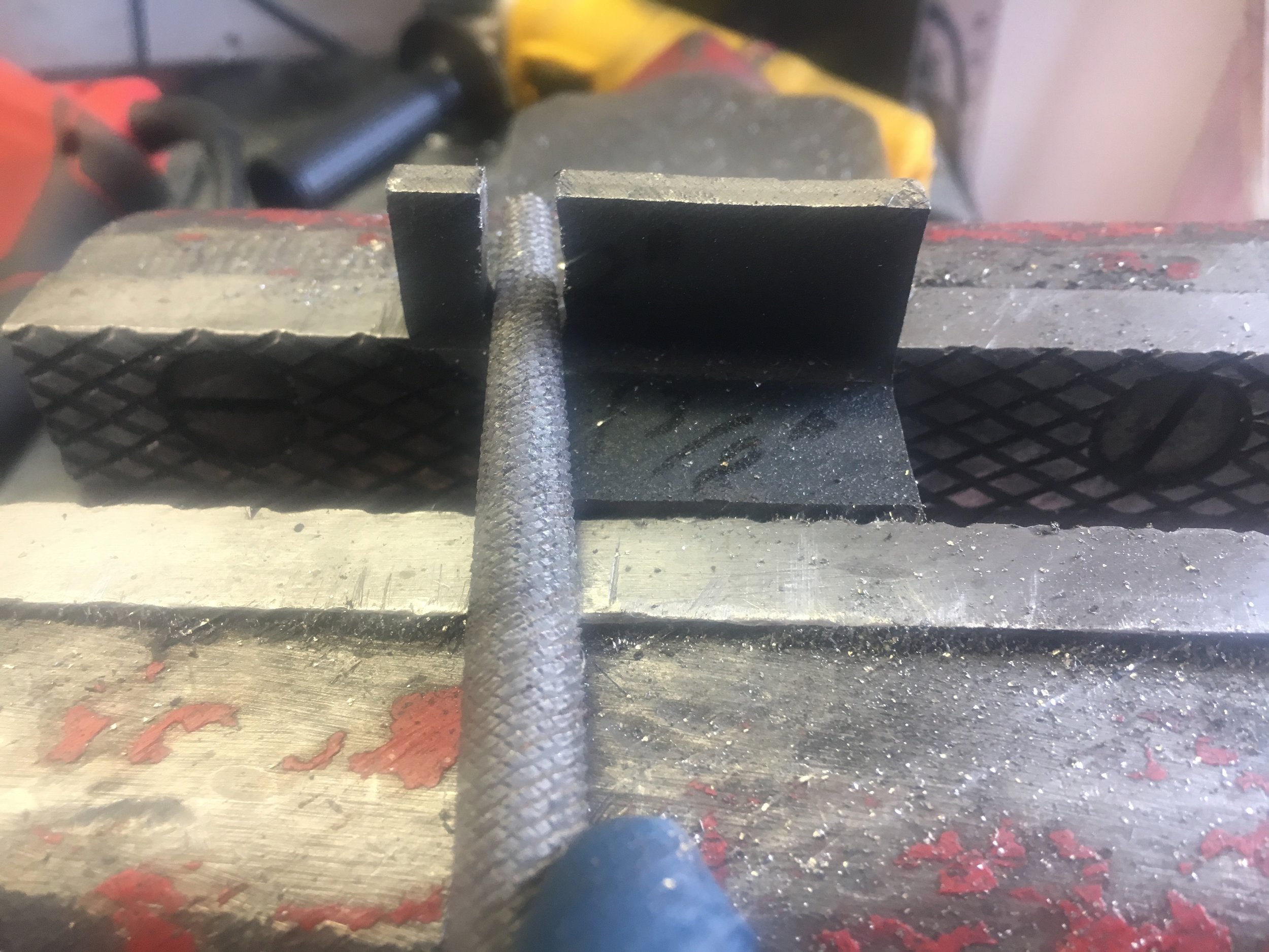
Double check the diagram for the correct measurement, adjust the components in the vise as necessary, clamp them up tight and make two or three index marks:

As an alternative to the index marks, this owner drilled the parts and installed rivets to hold the alignment and inboard-outboard relationship, before taking the part to be welded:
![20200625_152207[1].jpg](https://images.squarespace-cdn.com/content/v1/543af5a2e4b039cd17f66c87/1593141258259-L0N95Z8PD8F04UM09CGV/20200625_152207%5B1%5D.jpg)
![20200625_152118[1].jpg](https://images.squarespace-cdn.com/content/v1/543af5a2e4b039cd17f66c87/1593141272104-86JNKM9F73QGB4DHPP5T/20200625_152118%5B1%5D.jpg)
STEP 4 - Weld the Components Together
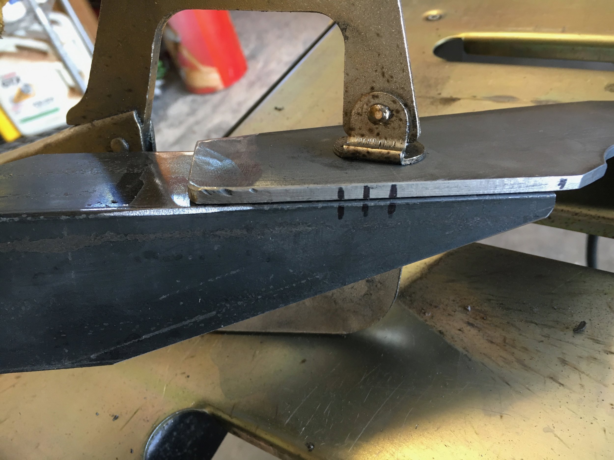
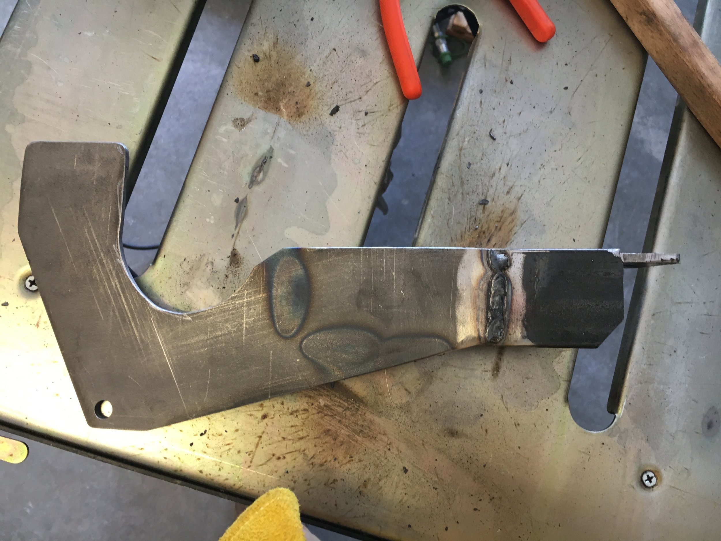
Prepare the steel, align the parts using your index marks, and weld as shown in this photo series. The discoloration shows where the mount was welded on the reverse side—along the bottom and outboard end of the angle iron:
STEP 5 - Add Provisions for a Second and Third Idler Pulley
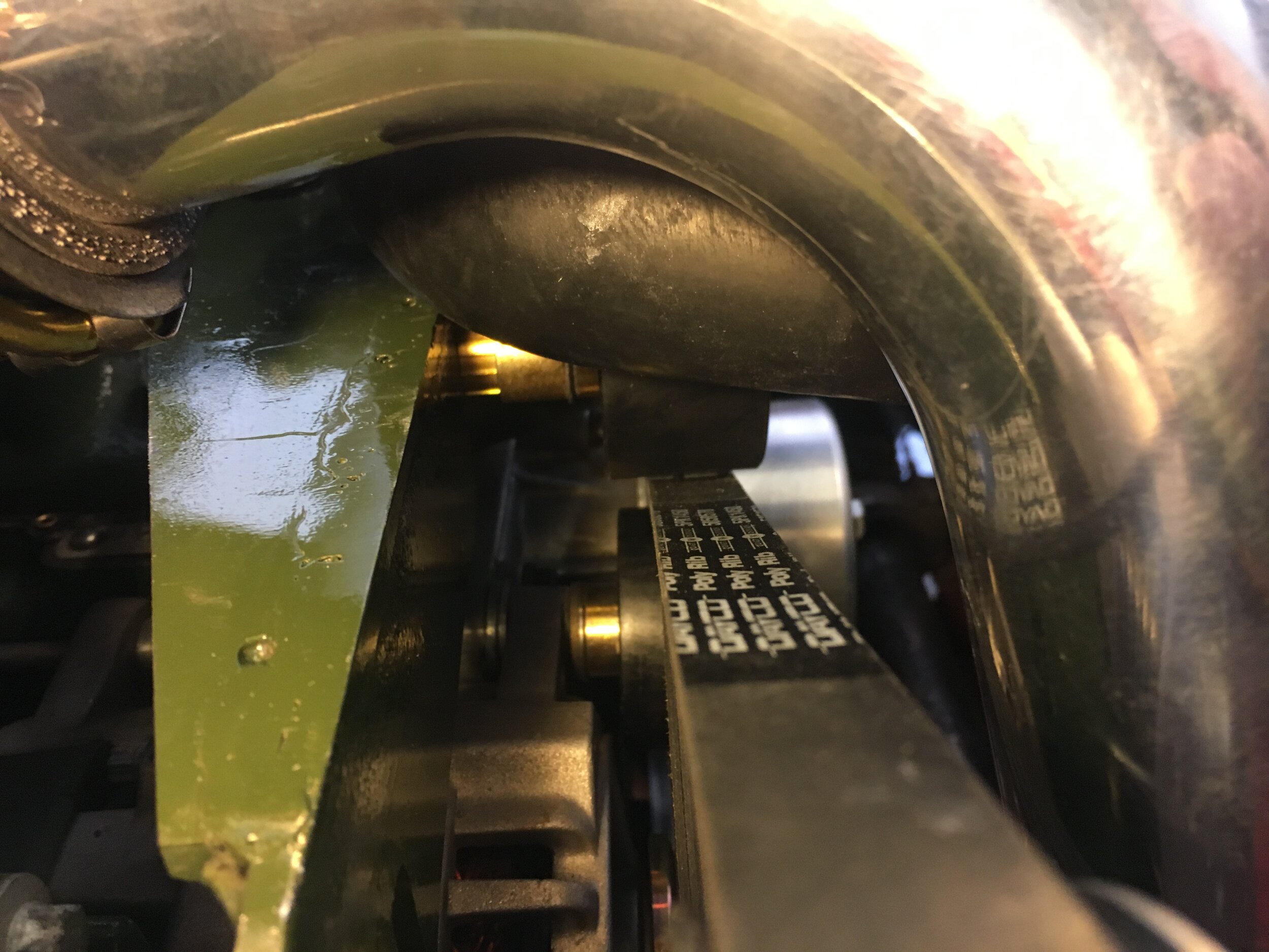
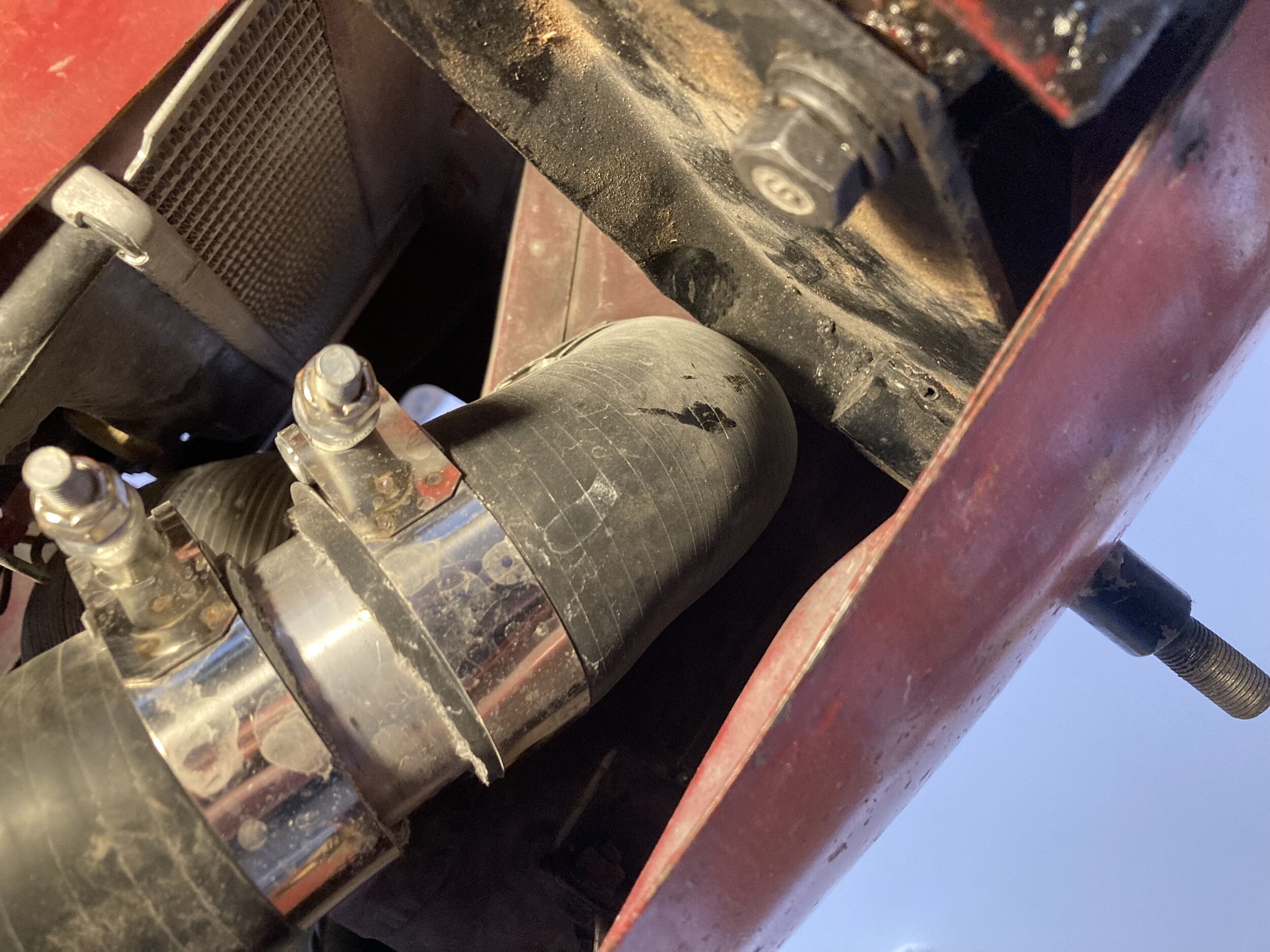
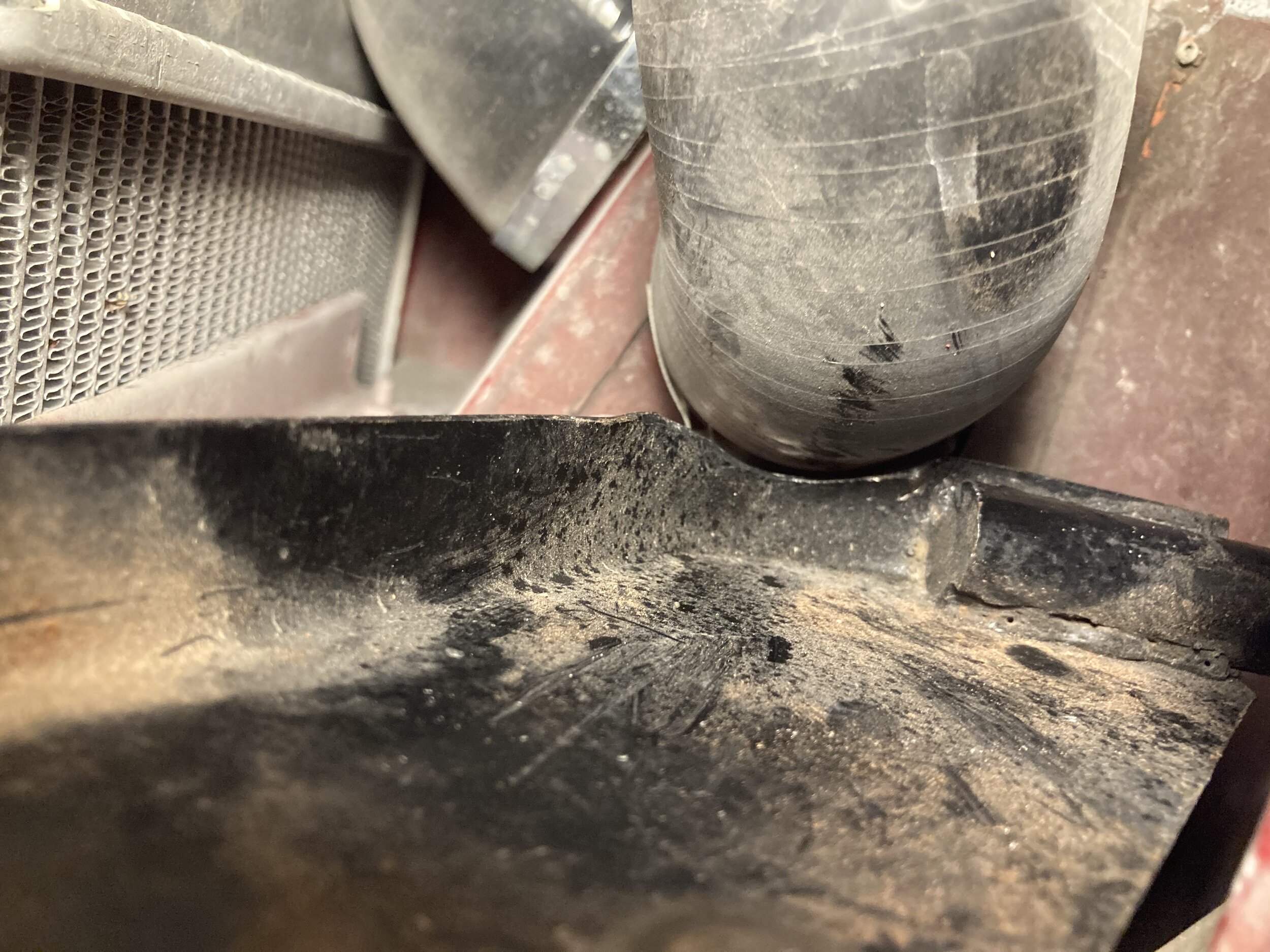
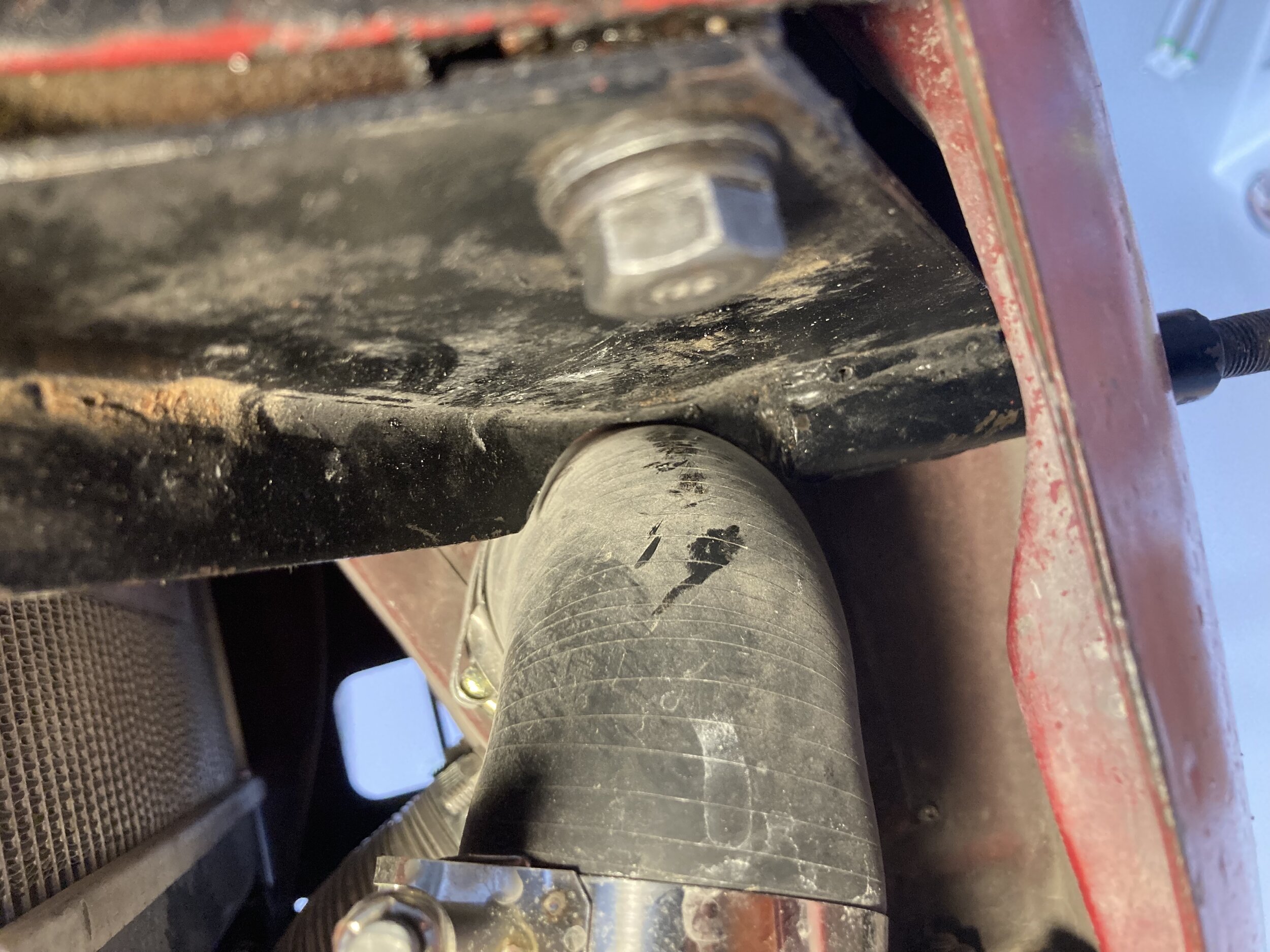
Beta testing of the system revealed that cars with either an early down-flow radiator or the VW Rabbit (Golf) radiator installed on the author’s car required a second idler pulley to avoid the serpentine belt’s long top run from flapping on sudden deceleration and contacting the underside of the top radiator hose:
The solution—adding provisions for a second and third idler pulley—is straightforward and has the additional benefit of adding significant preload adjustment of the serpentine belt. The preload adjustment affords greater flexibility in running larger or smaller supercharger pulleys as discussed later in the section on tuning the system.
The process involves drilling two or three 3/8” holes and connecting them with a Dremel cutter wheel, then finishing the slots with a file to facilitate vertical adjustment for the additional idler pulley, as shown in this photo series (the second, outboard slot is for a third idler pulley, just in case it becomes necessary):
First, measure from the inboard edge of the front mount where it contacts the side of the head, and mark the centerline of each slot at approximately 1.5” and 5.75” (but see the discussion in a moment about flexibility in the first measurement for people who chose to weld the lap joint on the front of the mount):

Second, drill two or three 3/8” holes and connect them with your Dremel cutter wheel. The holes’ vertical orientation isn’t critical. Just leave plenty of steel along the top and bottom so as not to weaken the front mount.
*Note: you can also just drill one hole (and rely on the third idler for belt preload adjustment, if that ever becomes necessary). Its location would be .75” down from the top surface of the angle iron that forms the inner component of the front mount, and 1.5” out from the vertical edge that contacts the head.
The third image shows a spacer (the same diameter as the smaller section of the combo bushing/spacer in the parts list) placed next to the lap joint of the front mount’s two components, to make sure there was sufficient lateral clearance:
The author did not weld along the forward face of the lap joint (an earlier picture showed another set of mounts), so he welded along the top seam for added strength, and then ground the weld:

If your mounts feature a weld along the lap joint, do not worry. There is room to position the slot a little farther inboard (toward the head) without causing the idler to contact the head, as the next picture shows. Note, for those purposes, that in the next picture, the clearance between the idler and the head is .25~.33”.
Or you can grind your weld a little to make room for the spacer if you prefer:

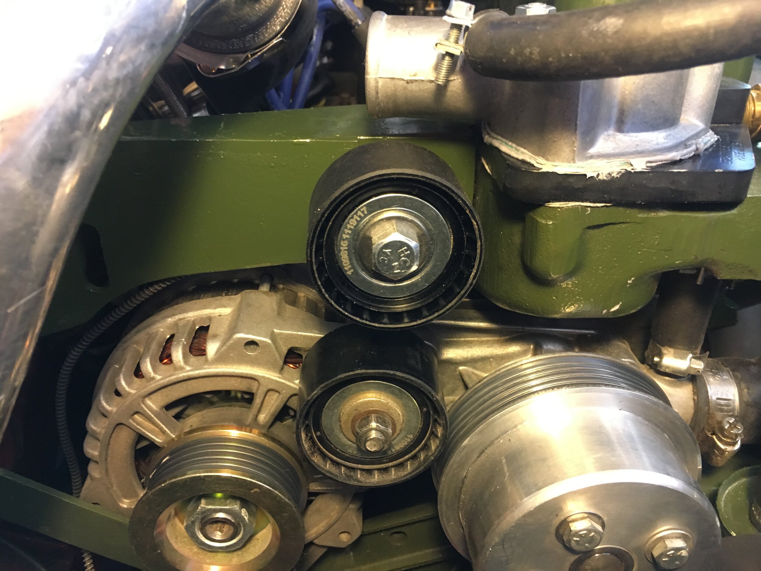
STEP 6 - Align the Pulleys
As stated at the outset of these instructions, in order to align the pulleys and complete the front mount, you must have converted to a serpentine belt drive as described here. This operation must be done with both mounts bolted to the engine and the supercharger suspended from the rear mount.
First, install the rear mount and position it in the center of the fore-aft adjustment:
Second, hang the front mount on the cylinder head stud. These photos show the alternator with idler pulley and support strut installed:
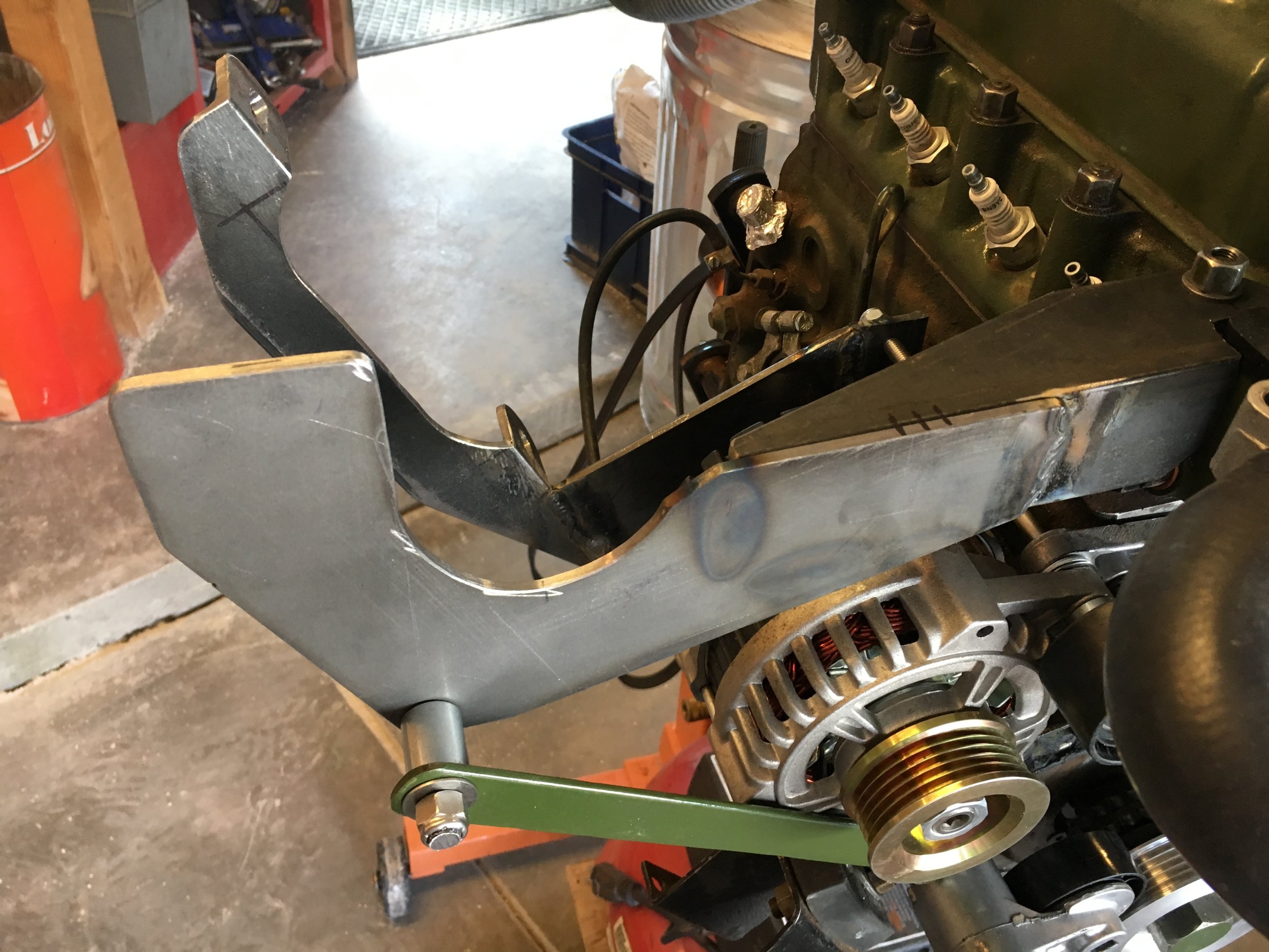
Third, to align the pulleys, bolt the supercharger to the rear mount, placing the screws in the middle of their adjustment range:

Fourth, using a framing square or long straight-edge, check pulley alignment both above the supercharger’s drive shaft and against the water pump pulley, and below the shaft and against the alternator and crankshaft pulleys, as shown here:


Make adjustments as necessary, using the twin 5/16” bolts affixing the rear mount to the engine block for gross fore-aft ‘range’ adjustments, and then moving to the bolts holding the supercharger to the rear mount for finer adjustments.
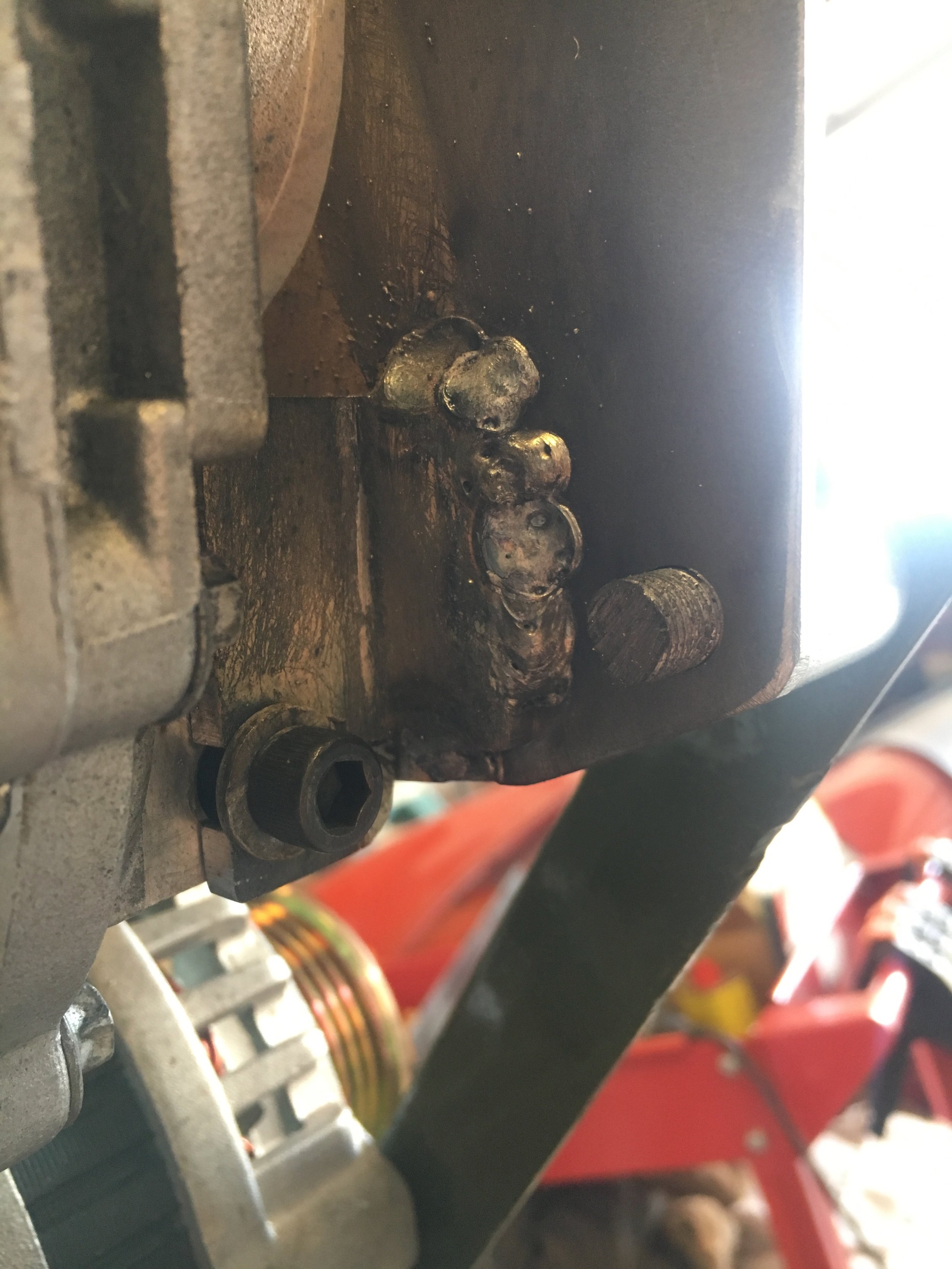
Once the alignment is reasonably close (you will finalize it later), you are ready to fabricate and weld on the tabs connecting the supercharger’s mounting ears to the front mount as shown here. The dimensions should be confirmed by frequent test-fitting to make sure the tabs afford sufficient fore-aft adjustment—but this process is greatly simplified by bolting the supercharger to the rear mount and aligning the pulleys.
STEP 7 - Fabricate and Weld the Lower/Inboard Tab:
First, cut the basic shape from mild steel angle iron:
Second, mark and drill the longer leg of the angle iron, make two parallel cuts, and finish with a round file to form a U-shaped channel:
Third, round the edge that will face forward and test fit the mounting tab:

Fourth, break the edges and strip off the protective coating to produce the finished part, ready for welding

Fifth, jig up the lower mounting tab and weld in place.
*Note: if welding the tabs somewhere other than where the engine is located, simply clamp them in place as shown below, then trace around their outline and make index marks carried from each tab onto the front mount.
Be sure to remove the protective coating on the front mount itself for an inch or so around the tab:
STEP 8 - Fabricate and Weld the Upper/Outboard Tab:
The upper mounting tab is much simpler.
First, cut a 1-1/4” section of 2” mild steel angle iron and trimming one side approximately 5/8” to produce shorter (1-3/8”) and longer (2”) legs.
Second, round the longer leg or at least eliminate the sharp corners.
Third, drill two holes in the longer leg to begin forming the adjustment slot:

Fourth, connect the holes with a Dremel or small cutter wheel in a drill motor, and test fit the mounting tab, ensuring that the slot provides sufficient fore-aft adjustment. At the same time, mark the front mount to indicate where you will remove the protective coating before welding:

Fifth, weld the tab onto the mount:

*Note: if you are using rosin core wire instead of shielding gas, you may wish to put a rag over the blower to avoid the splatter in the above photo. However, the rosin deposits are easily removed with #0000 steel wool and Goof Off or a soft wire wheel in your Dremel or drill motor.
Here are the tabs welded onto the aft side of the front mount:

Finally, as with the front mount, degrease the part, break the edges, and finish with your preferred color of high-temperature engine paint:

The above mounts are painted OEM olive green, which contrasts nicely with the silver and black components, but this is a custom project. Do whatever strikes your fancy!
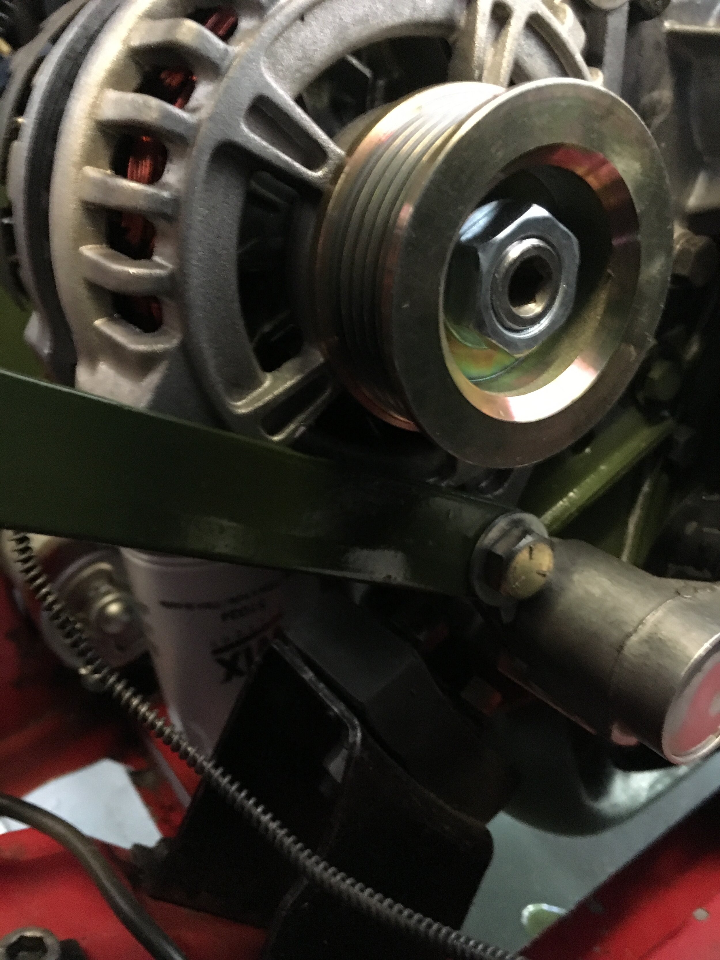
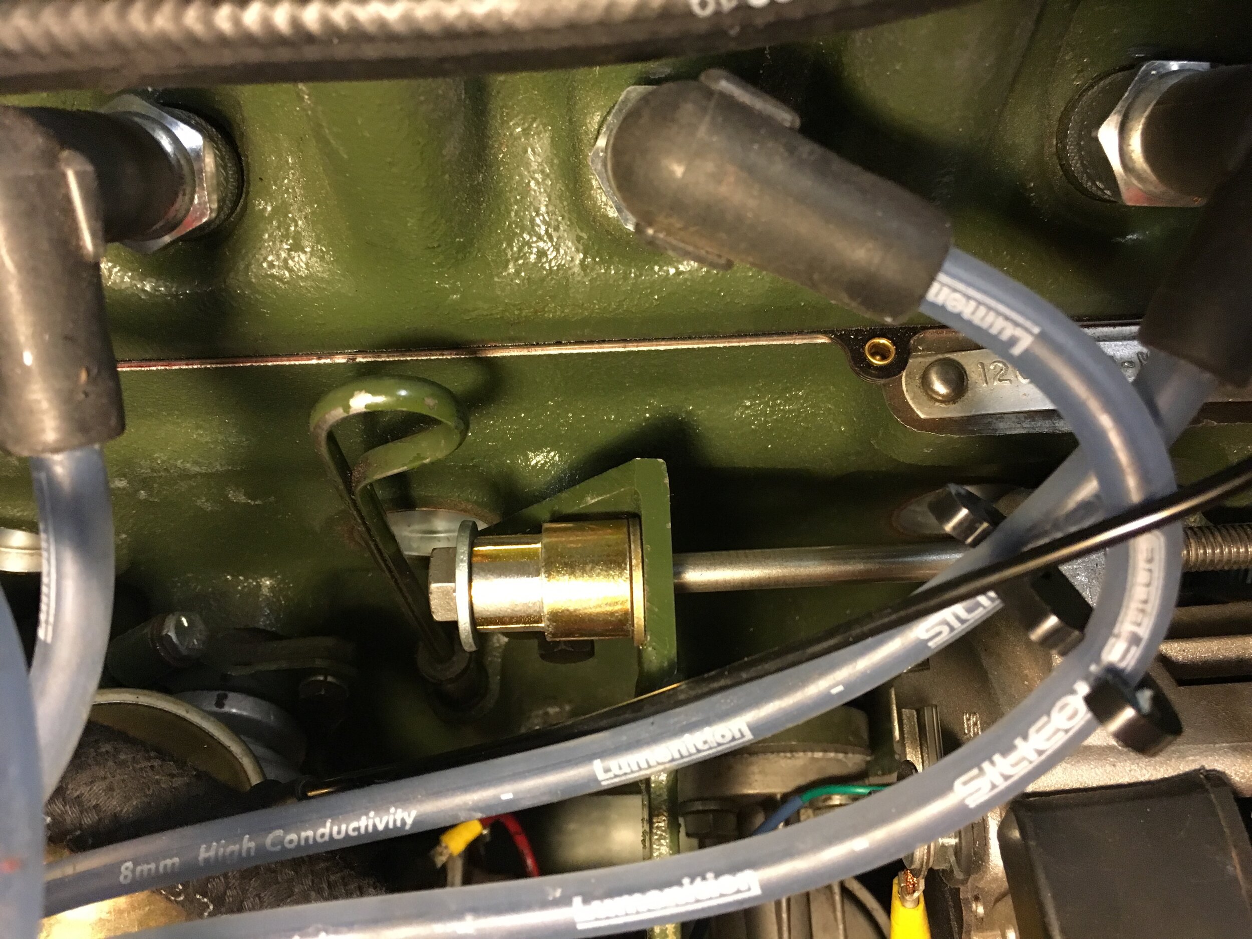
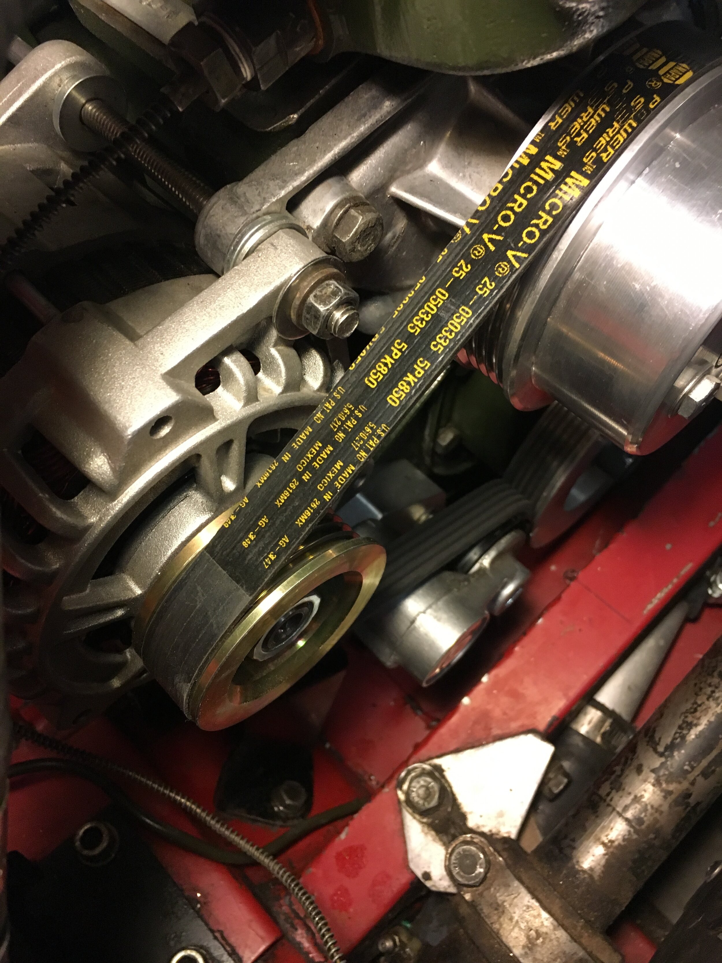
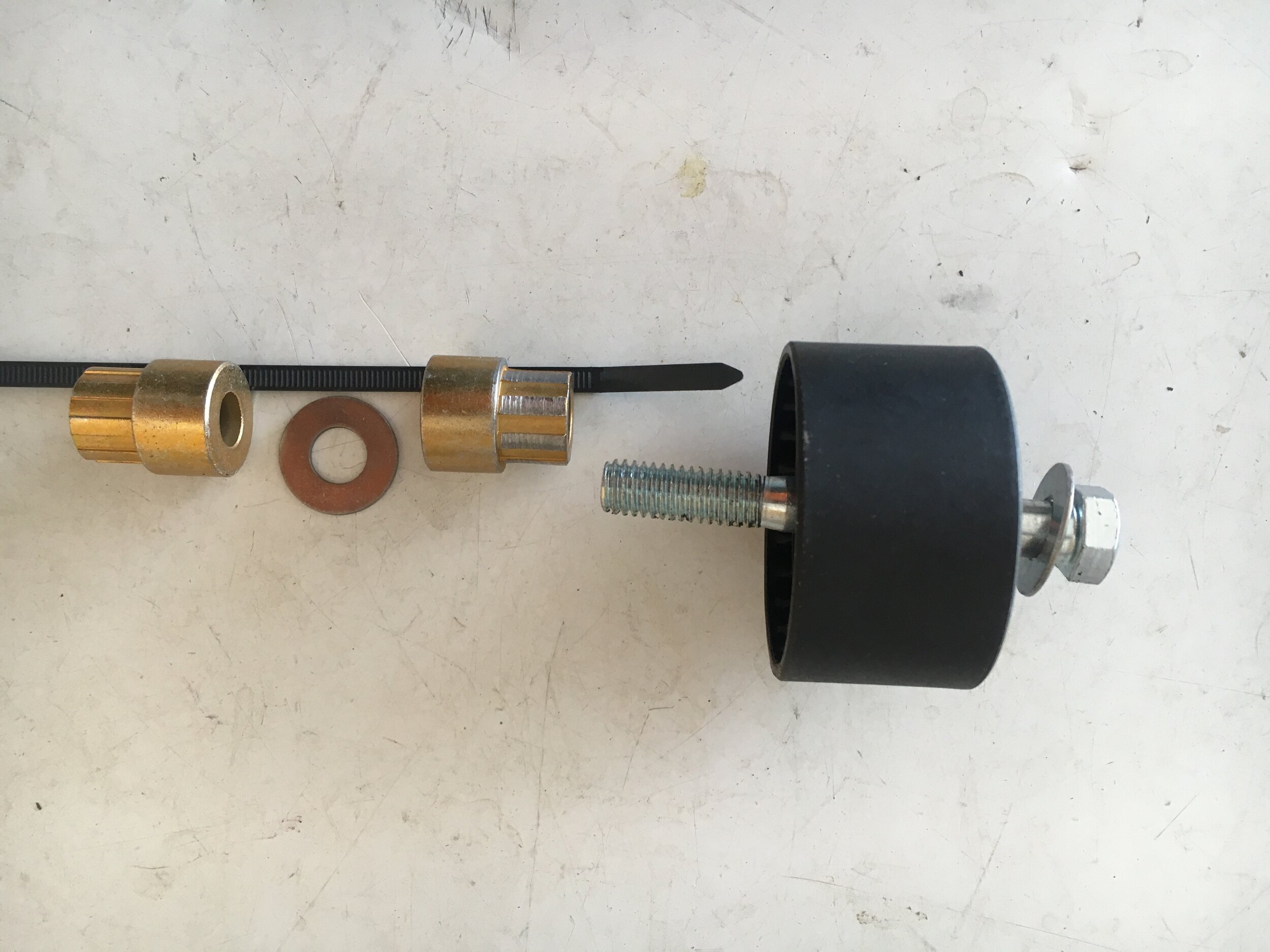
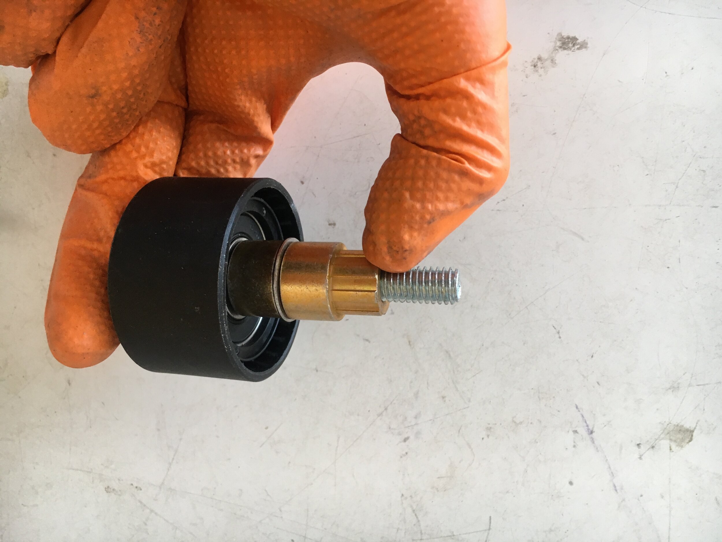
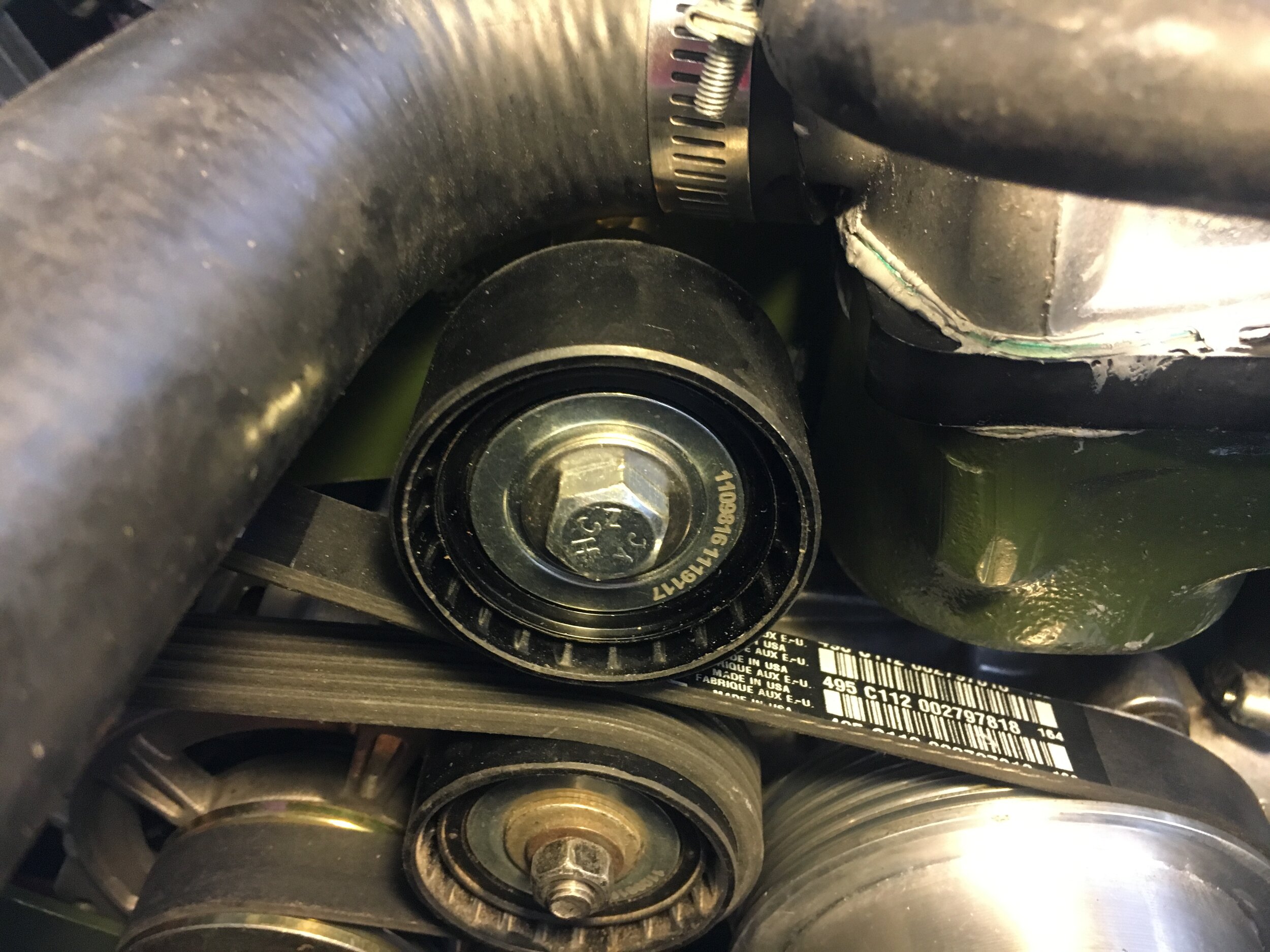
Installing the idler pulley
This conversion uses an inexpensive, late model Saturn CS121D internally cooled alternator (though it is compatible with the earlier Saturn and OEM Lucas alternators, and with additional fidgeting, even early Spridget generators).
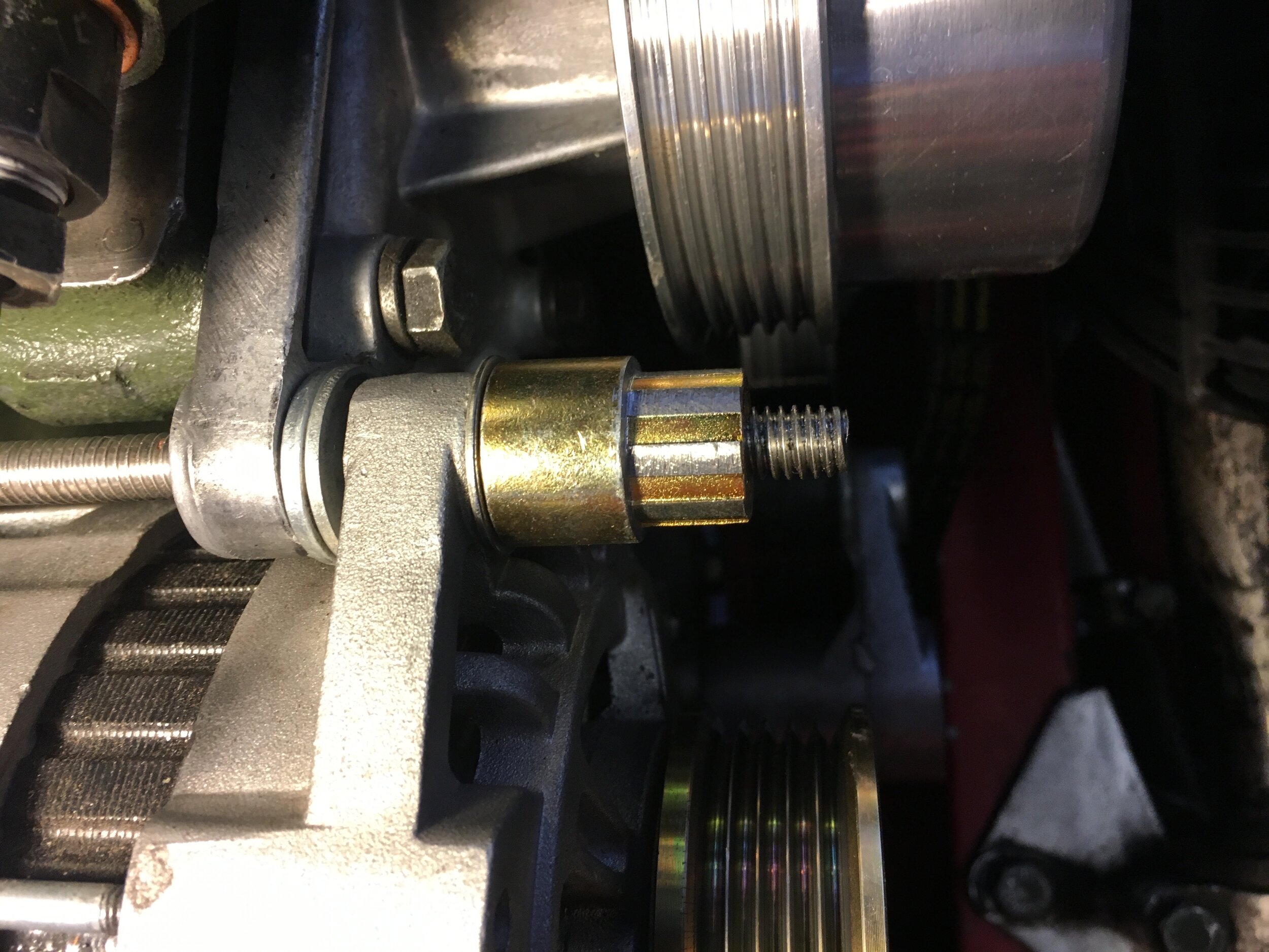
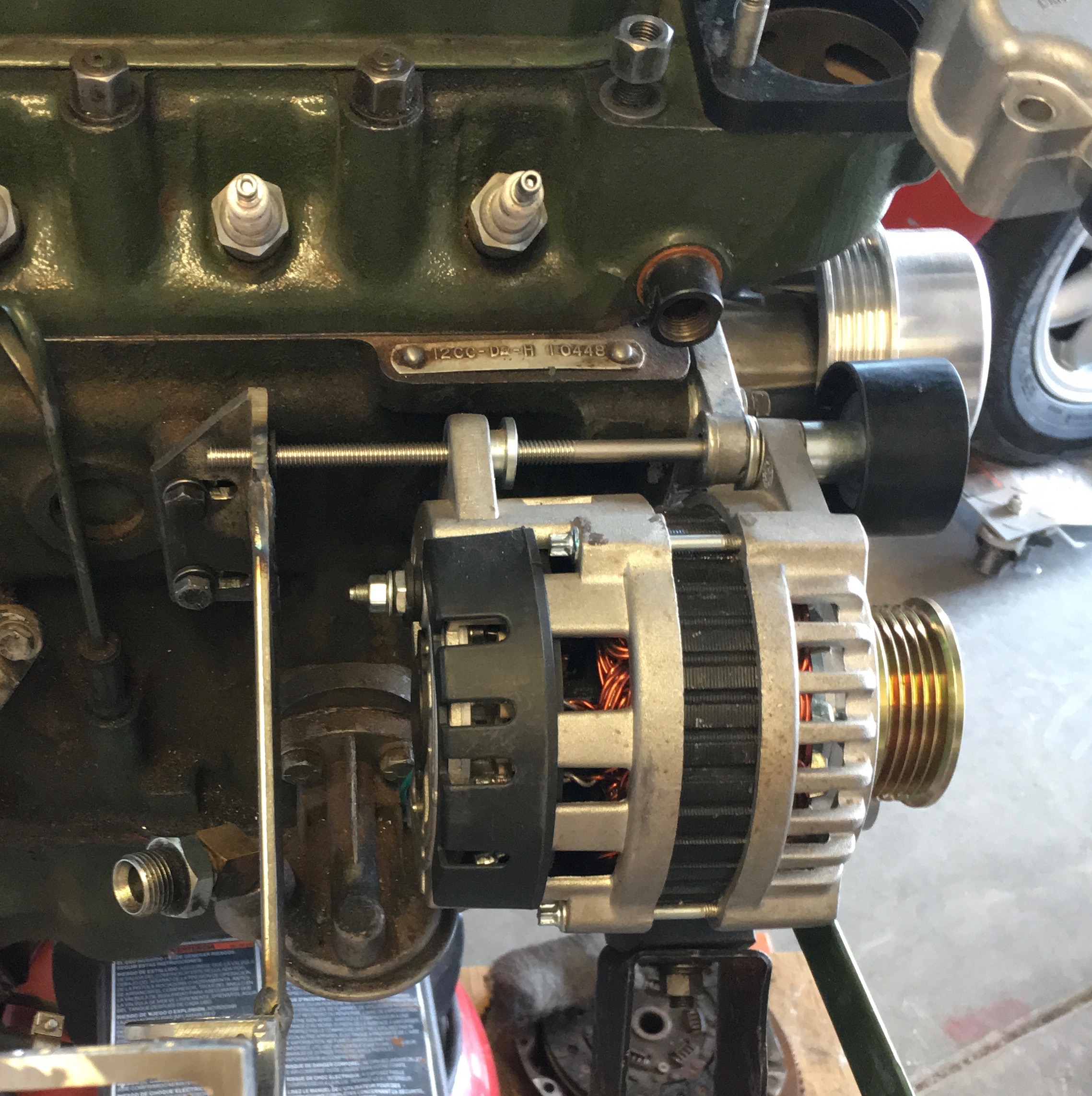
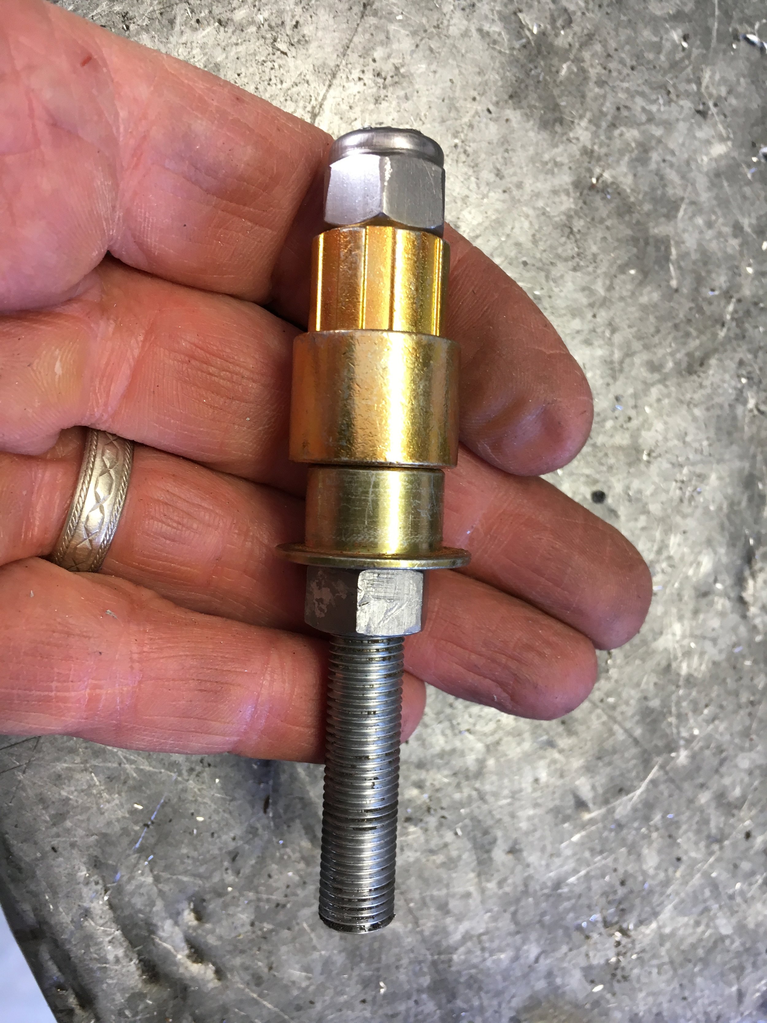
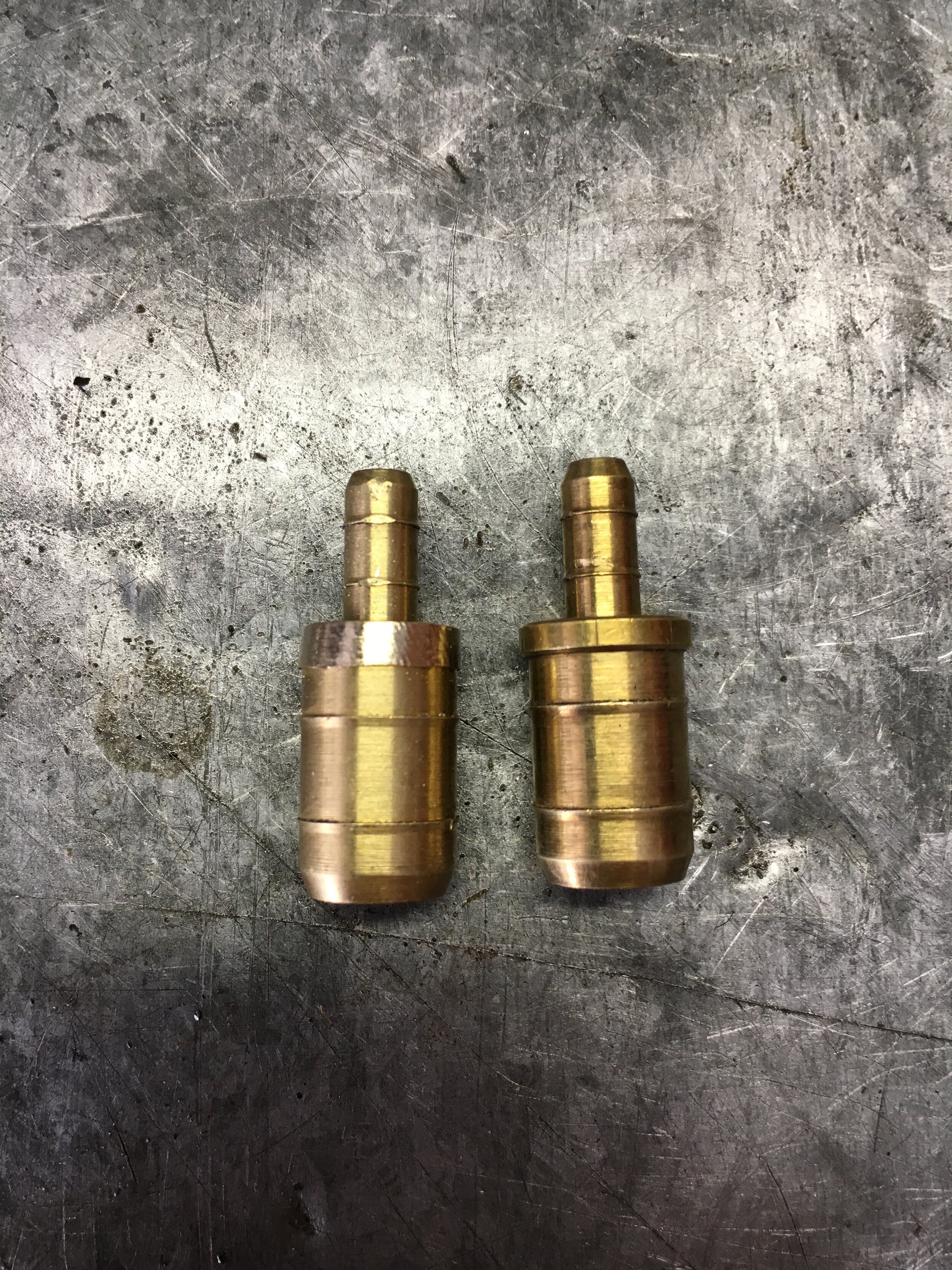
A single 8-1/2” long 5/16-18 bolt acts as the alternator pivot and mount for the 54mm idler pulley—Dayco part no. 8535, which turns on a combination bushing and spacer. This photo series shows the simple setup:

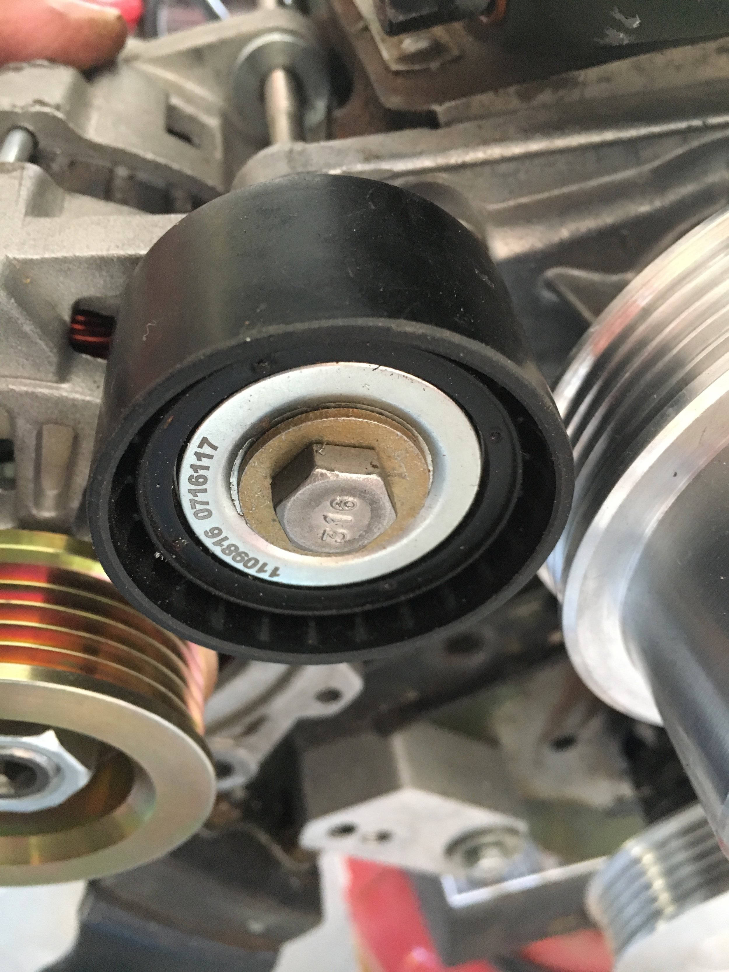
The highest quality combination bushing and spacer we could find is actually a lawnmower part. Its internal diameter is 3/8” but this does not affect is usefulness in this application.
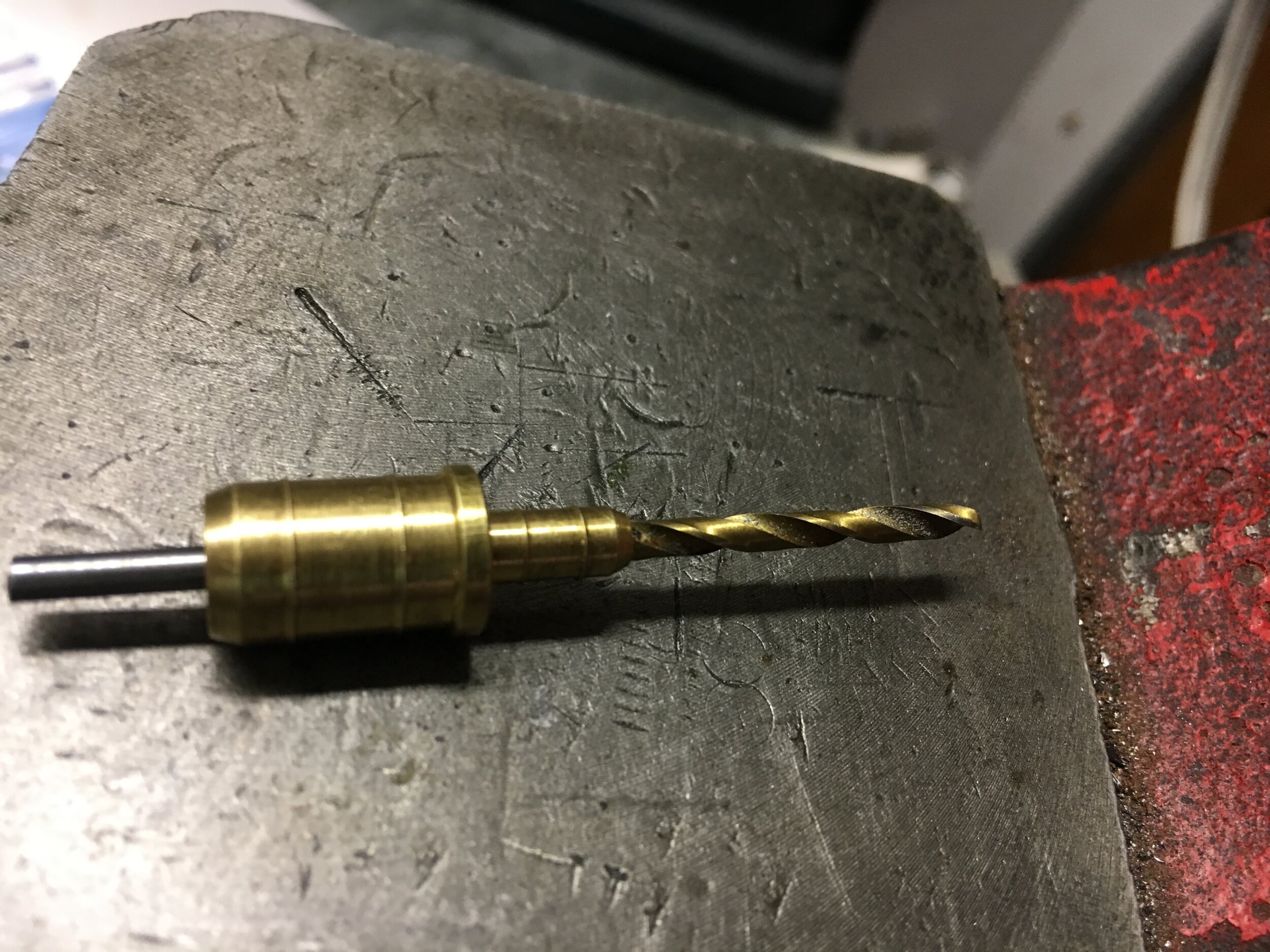
The bushing’s external diameter where it inserts into the idler pulley is a few thousandths over. Turning it for a light press fit takes just seconds using a drill motor secured in a bench vise, a length of 3/8” all thread or bolt, a couple of nuts and some washers. This photo series shows how to turn the bushing:
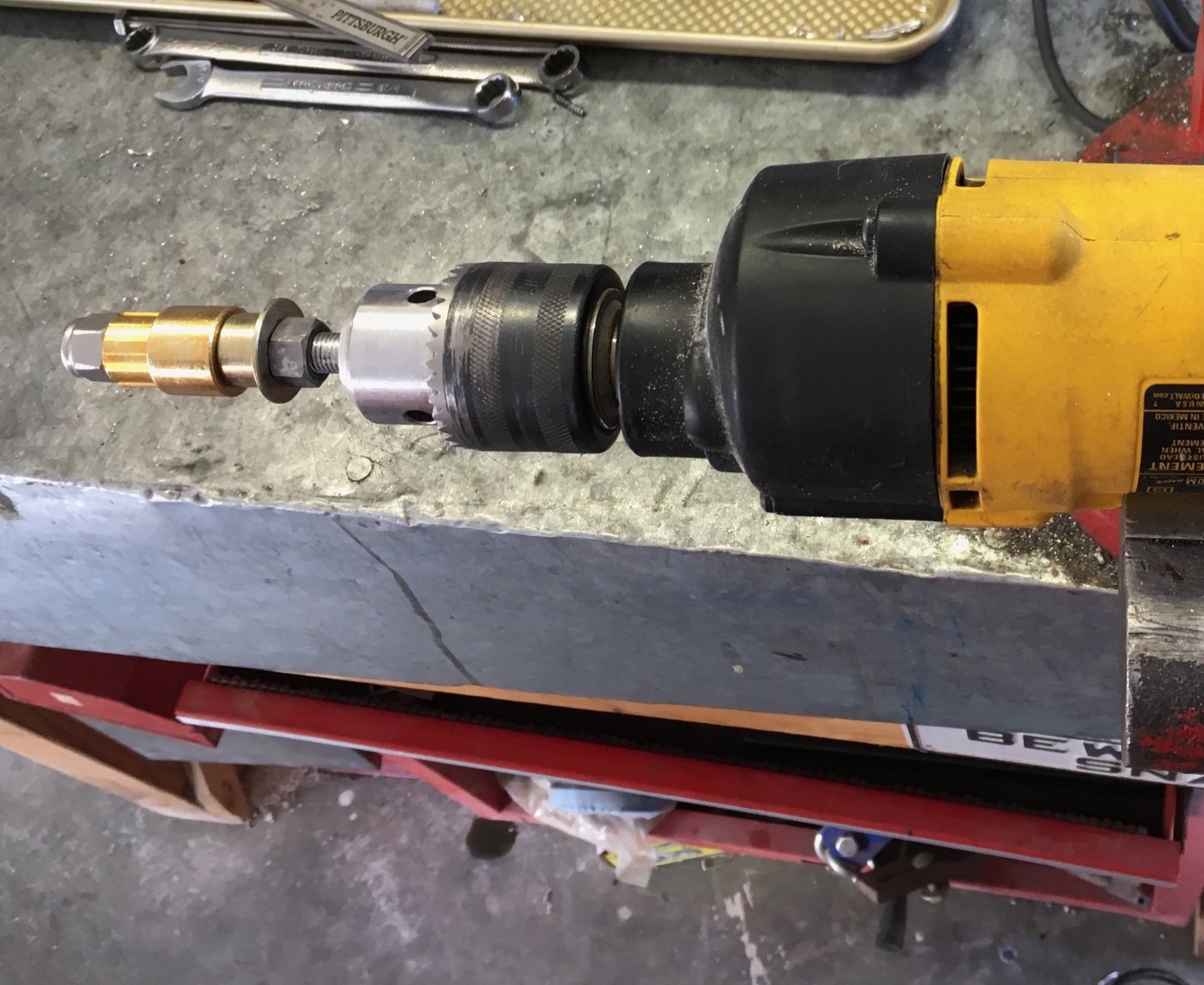
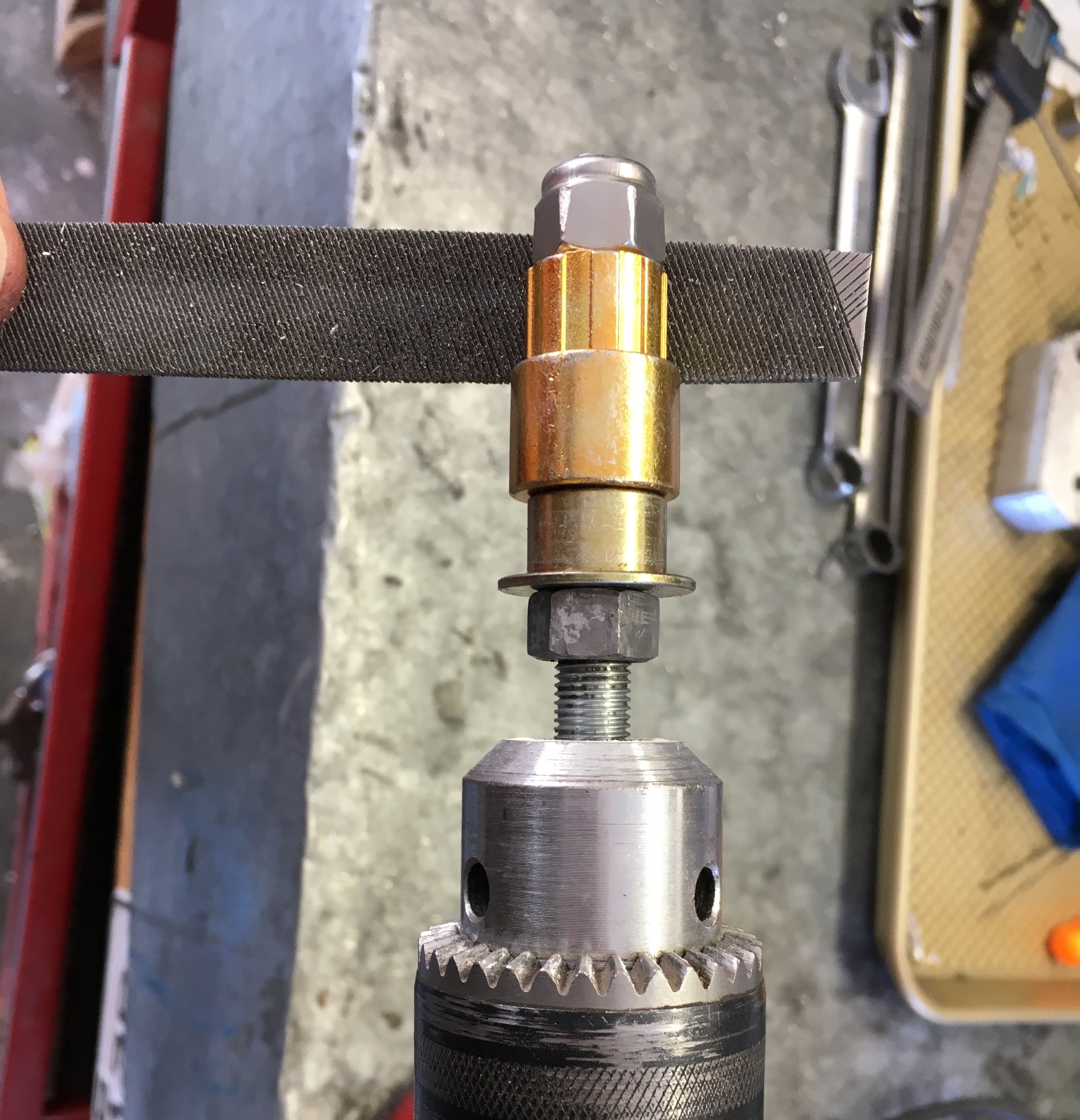
Use very light, even pressure on the file and check the fit often, as the operation only takes a few seconds. Make sure you are rotating the bushing opposite to the cutting direction of the file’s teeth, or things will go much slower.
relocate the horns
If your horns are located at the bottom of the well behind the grille and just in front of the radiator, they will need to be relocated to make room for the intercooler. While reusing the OEM horns is possible, we found that modern horns are both louder and more compact.
Here is one of the original Lucas horns fitted to the 1967 MG Midget test mule featured in these instructions compared with a horn from a 2009 Volvo C30 (which is similar to the S40):
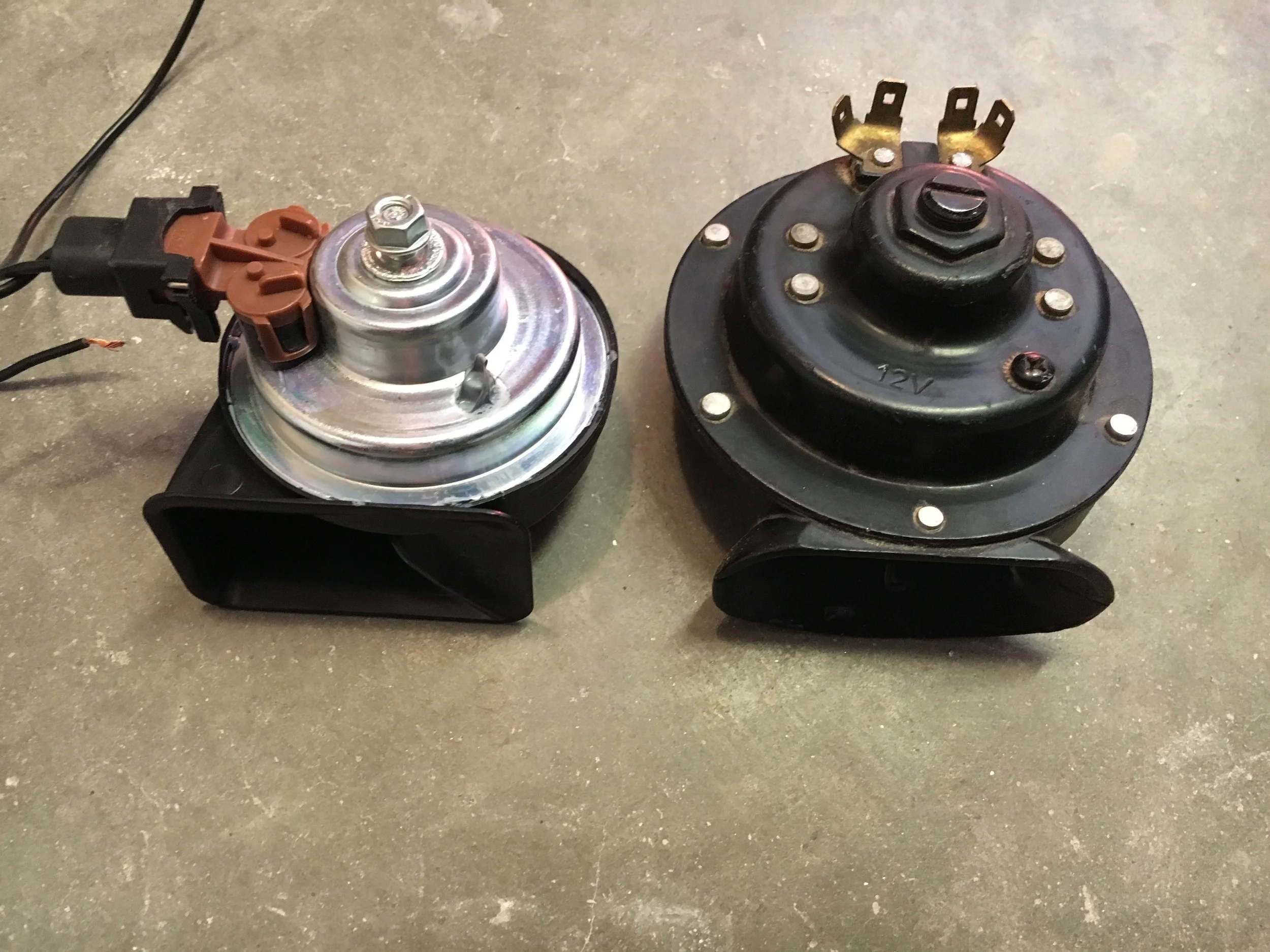
The Volvo horns have a similar tone to OEM Spridget horns but are slightly brighter and noticeably louder. They nestle underneath the sheet metal on either side of the bonnet latch mechanism, requiring only a single hole to receive the mounting bolt:


The leads from the horn’s pigtail hanging down in the first above photo will easily reach the OEM loom, which used to run down alongside the vertical support. The bonnet release cable is unaffected. (see the second above photo).
If you wish to mount these horns, they are Volvo part nos. 30796711 and 30796712 (low and high tones). The pigtails are not stocked by most Volvo dealers but are used for various auto electronic components. Common part numbers include NAPA 2-18457 and ACDelco PT113.
The horns do not draw much current, but you can install a relay if you like.
installing the intercooler
The Intercooler:
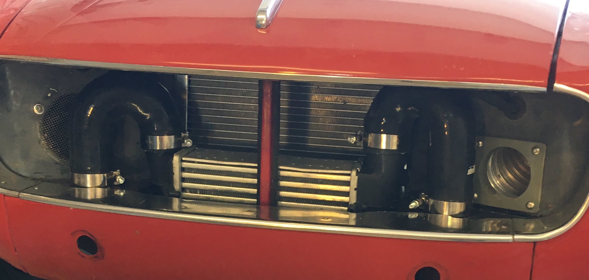
For the standard body MG Midget and Austin Healey Sprite (scroll to the end of this section for the Morris Minor), we recommend using this inexpensive 11-row intercooler from a 1999 Audi A4 1.8 liter turbo:

However, one installer has adapted a 14-row intercooler from a 2004-2009 Audi A4 2.0 liter turbo by trimming the unit’s plastic nipples and the silicon snorkels:
*Note: the taller intercooler should not affect engine cooling, for as soon as the car is moving faster than 15 or 20 mph, there should be ample pressure in the nose to move air through the radiator.
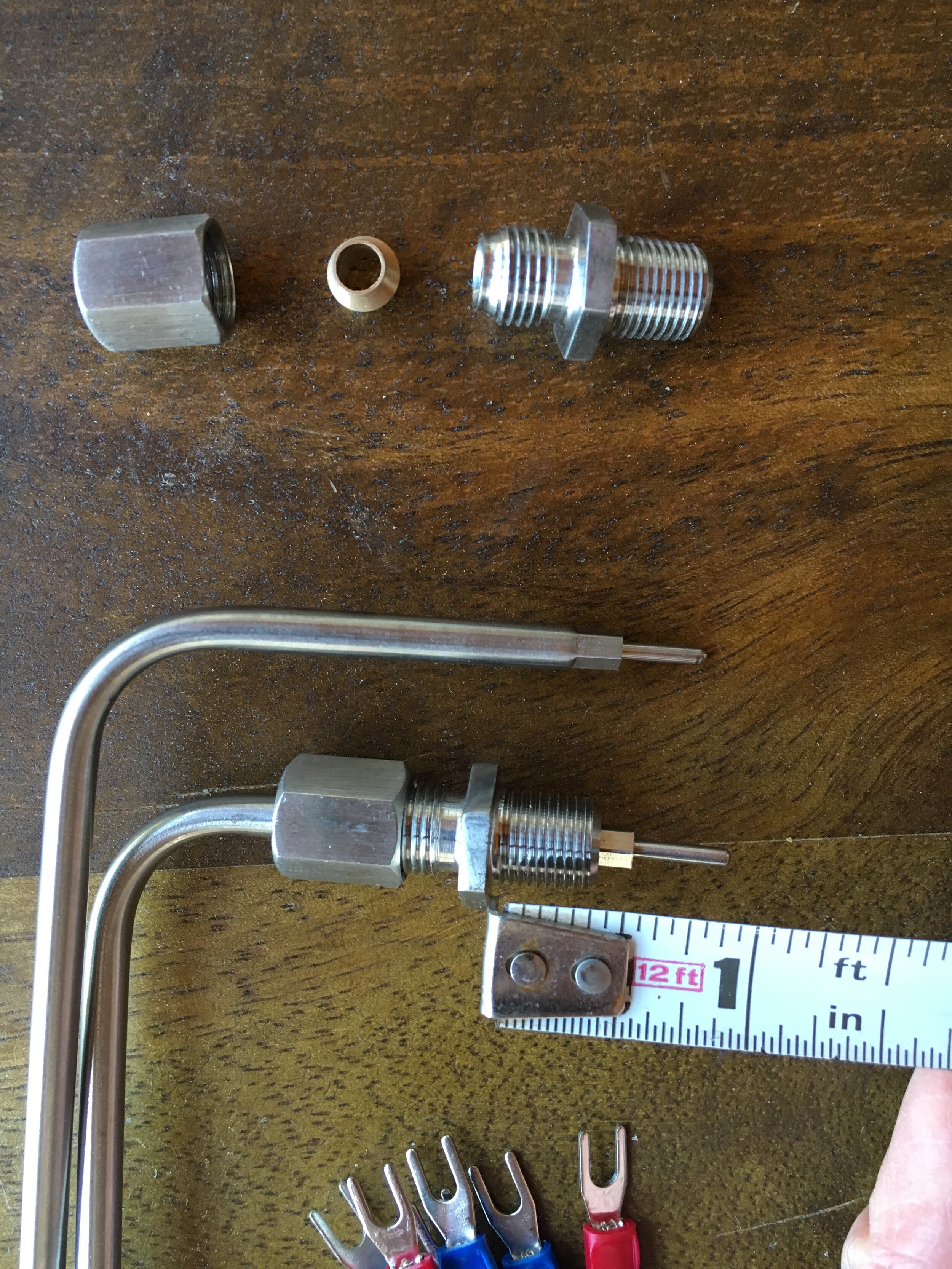
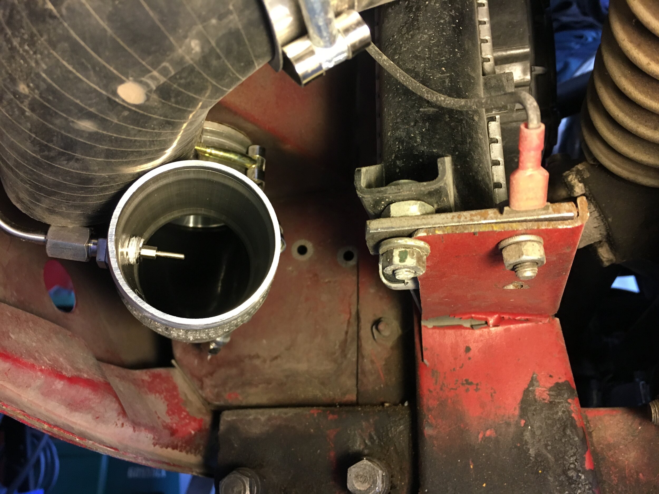
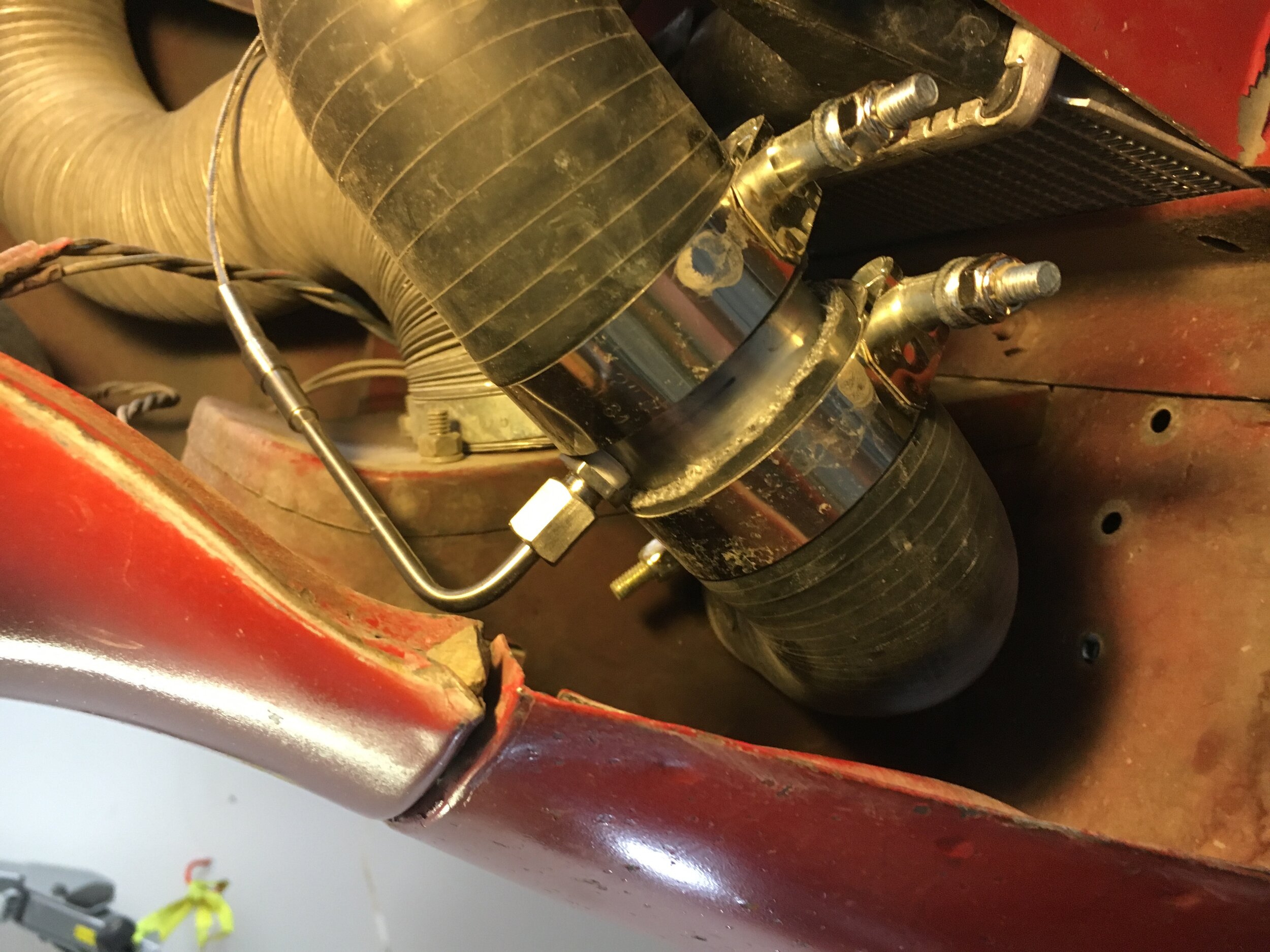
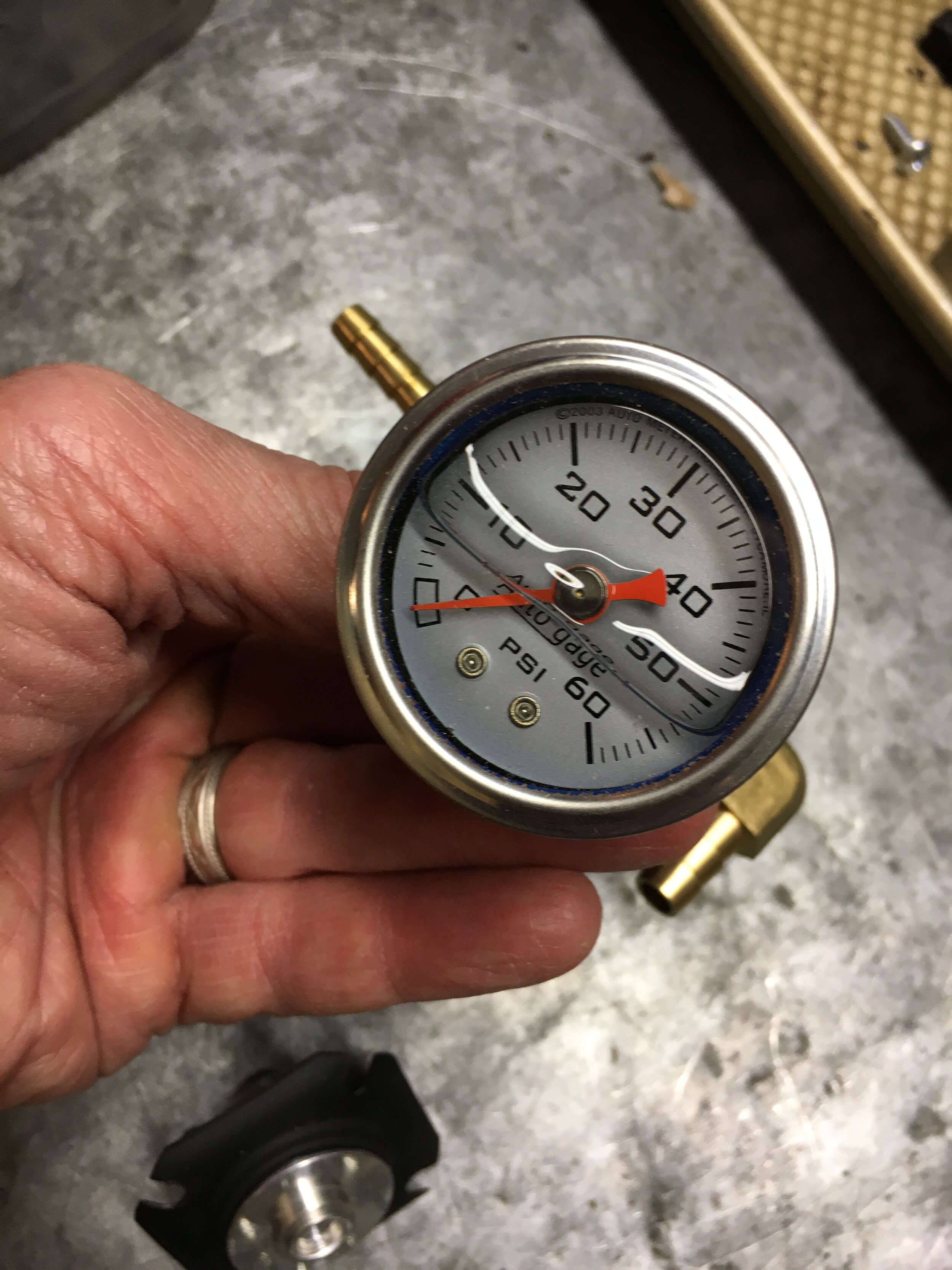
Even if you wish your conversion to remain entirely ‘stealth’ by concealing the intercooler behind the OEM grille as shown in this section, the 1999 Audi A4’s 11-row unit reduced the intake charge temperature in our test mule by as much as 127.8 degrees F. (53.22 degrees C.). The supercharger was generating 5 psi of boost at 5,000 ft. elevation (1,524 m.), with the car moving at 70 mph (112.65 kph), at an ambient temperature of 94 degrees F. (34.44 degrees C.):

We used the Auber 2813 gauge shown above, which is highly accurate and uses air temperature-specific probes with better accuracy than many of the available alternatives. Also, the probes are small enough to fit the 2” snorkels used in this conversion (opting for larger snorkels may slow the build-up of boost):
If you wish to optimize the intercooler’s efficiency, see the following section for a discussion about creating ducts in the lower valance to direct air flow onto the lower half of the intercooler’s core that is currently obstructed by the sheet metal.
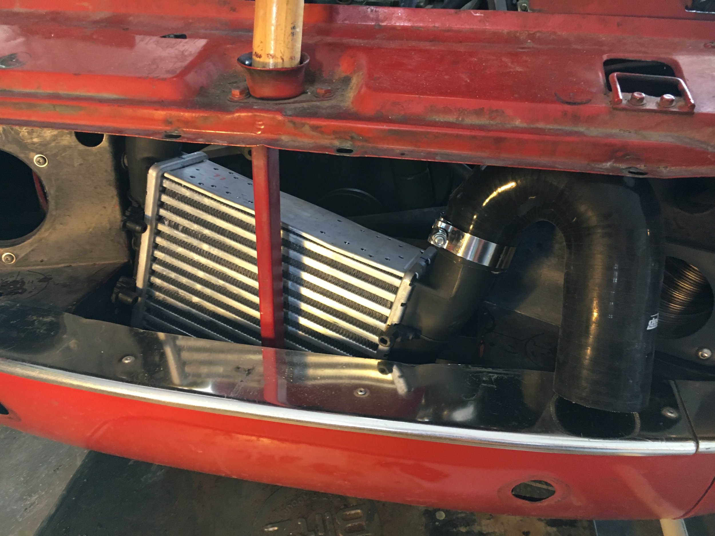
Installation:
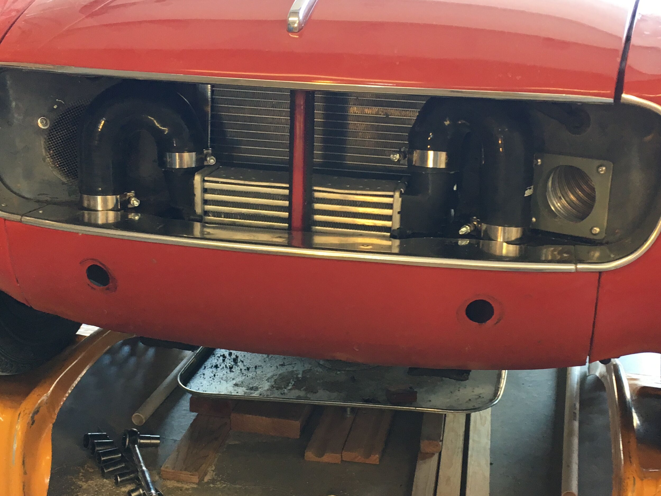
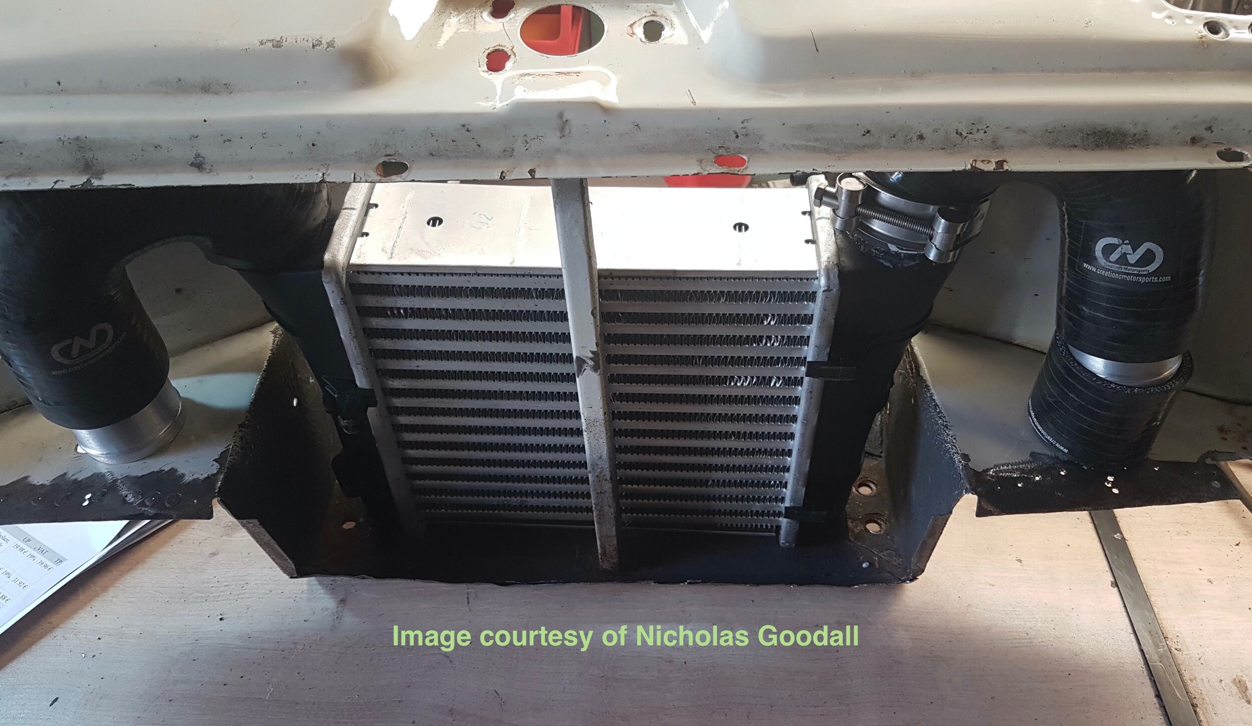
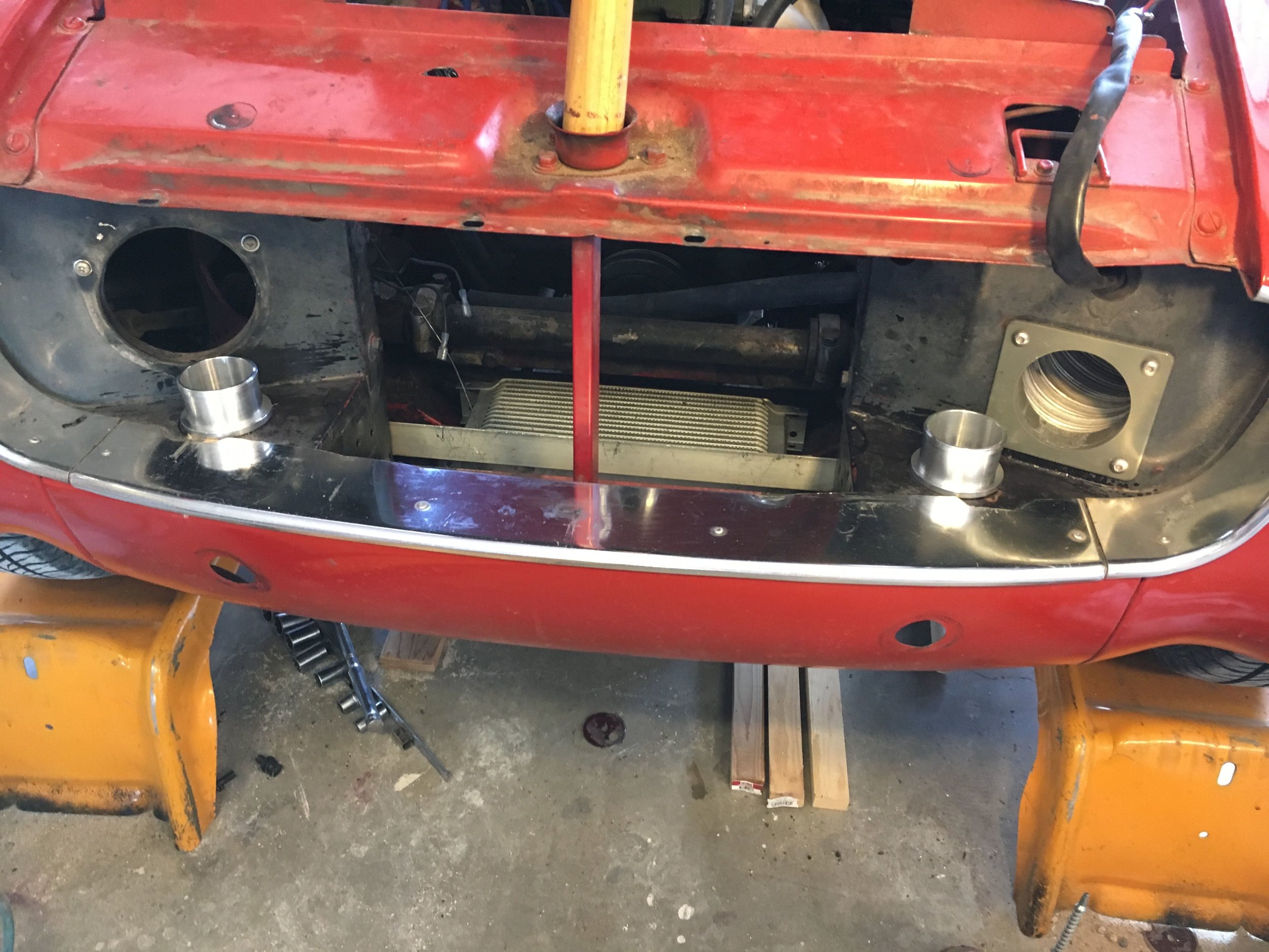
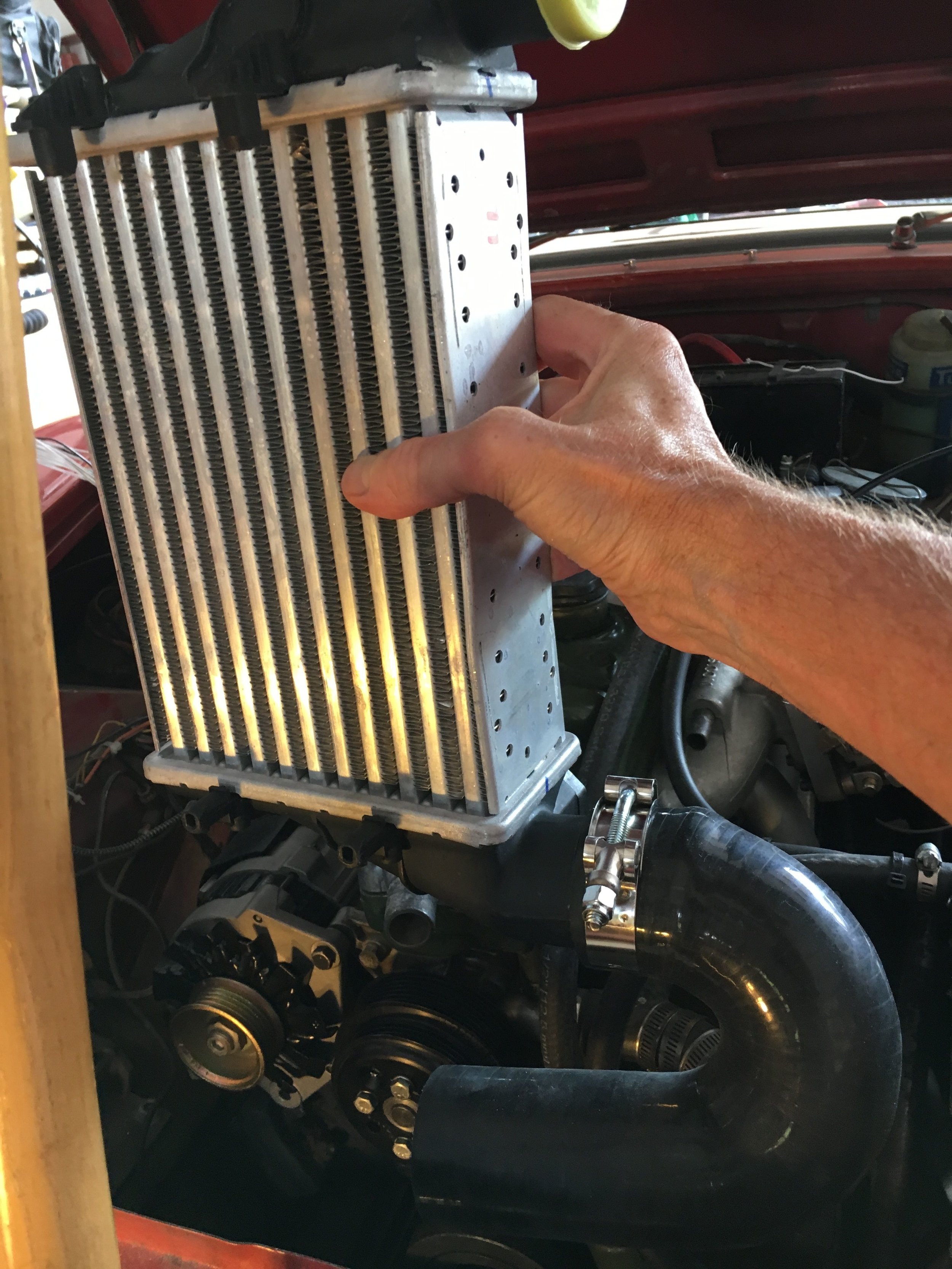
Below is a mock-up showing how the intercooler and tight-radius, U-shaped snorkels are assembled, absent the sheet metal for clarity.
*Note: the inboard leg on the snorkel on the left-hand side must be trimmed so the apex of the 180-degree turn will fit under the latch support sheet metal, due to the intercooler’s asymmetrical barbs, and one or both inboard legs trimmed so the outboard legs will reach the aluminum joiners passing through the sheet metal:

STEP 1 - Remove the grille and relocate the horns as described in the preceding section if they are mounted down in the well in front of the radiator.
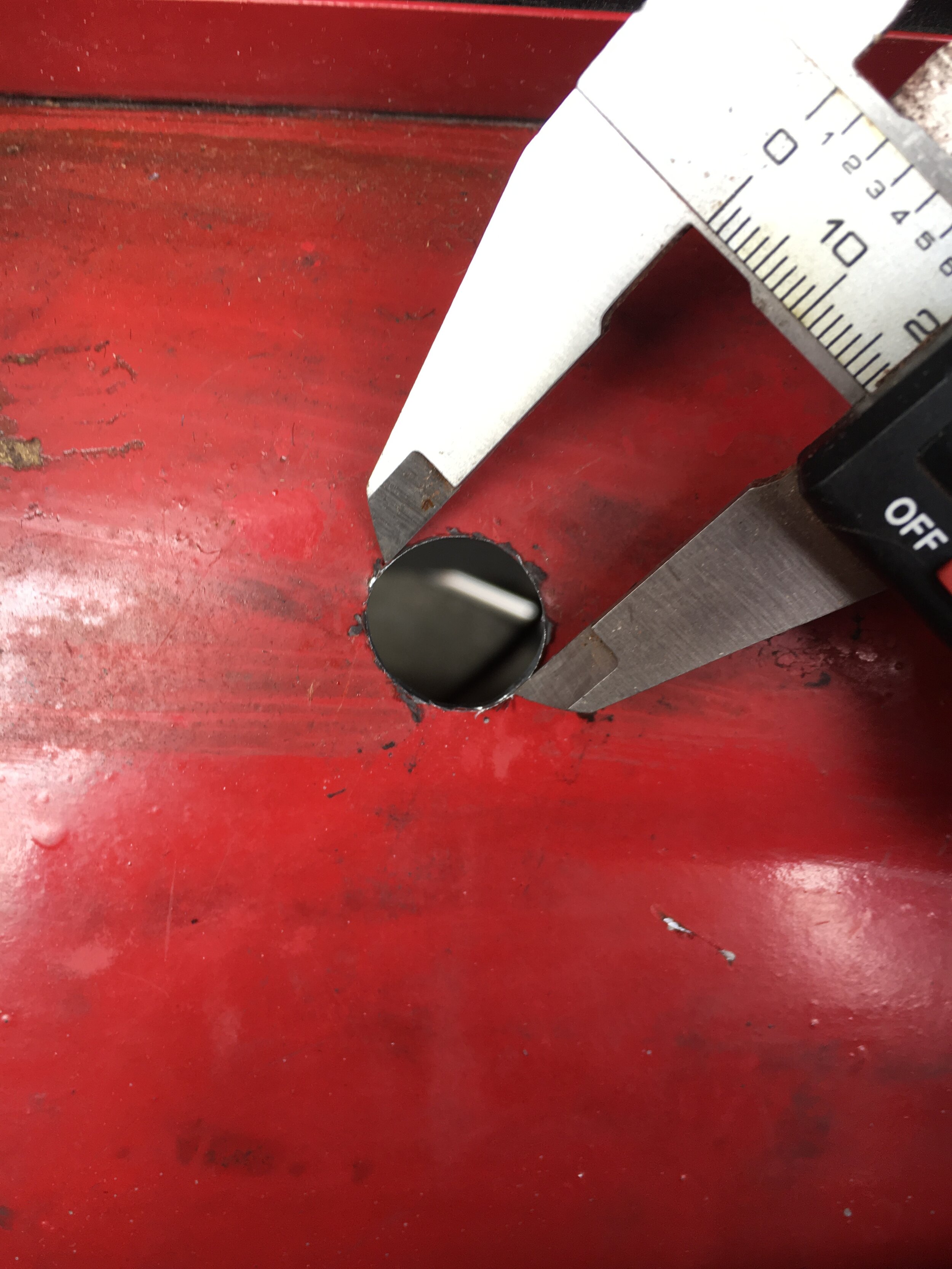
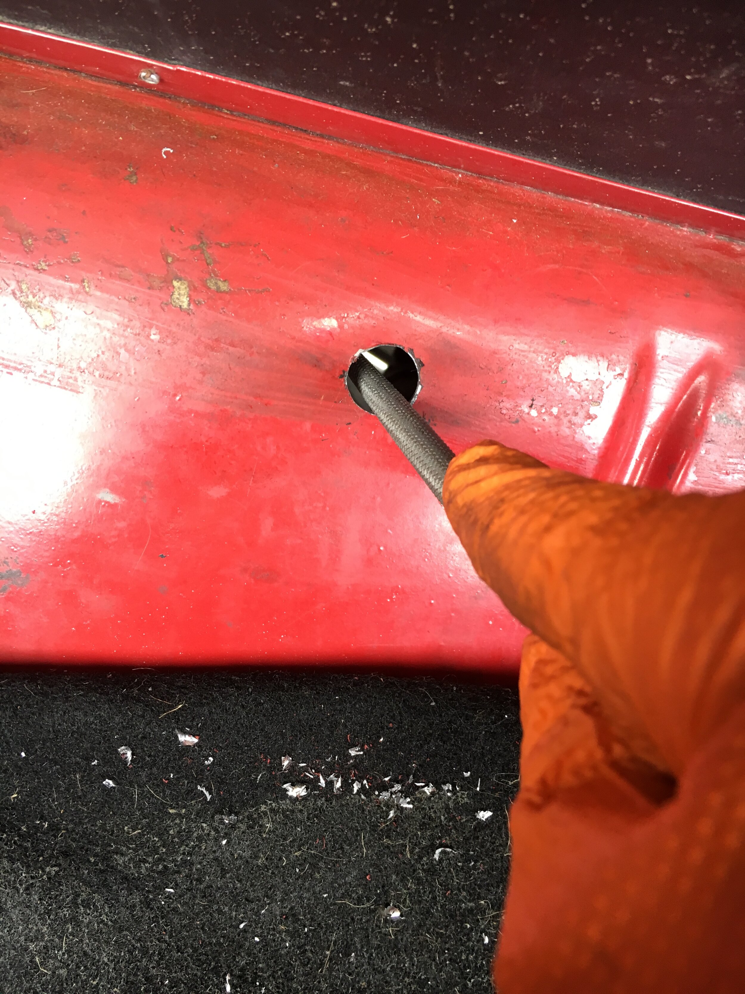
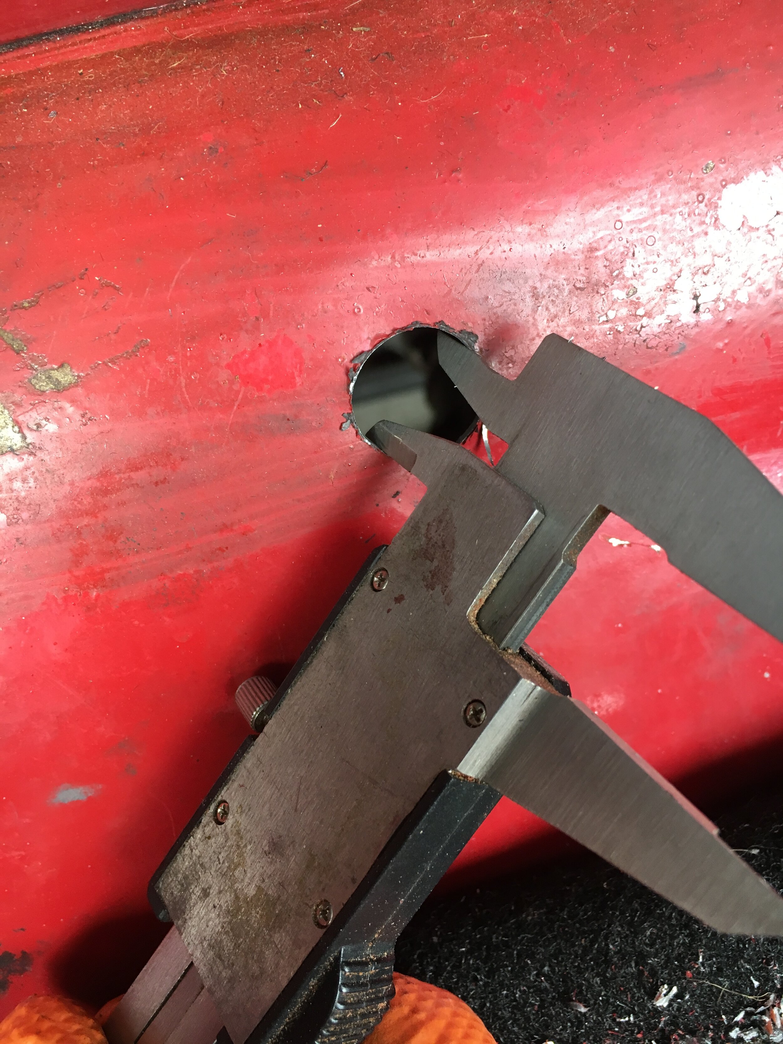
STEP 2 - Cut the holes in the front sheet metal for the snorkels.
You may use an arbored, bimetal hole saw available at any home improvement store as shown in the following slideshow.
Each hole will be cut from below, but these pictures show the pilot hole being drilled from above. If you cannot find or borrow a right-angle drilling attachment or a Dremel flexible gooseneck drive for the pilot hole, simply dimple the metal with a punch from above and drill the pilot hole from below, too.
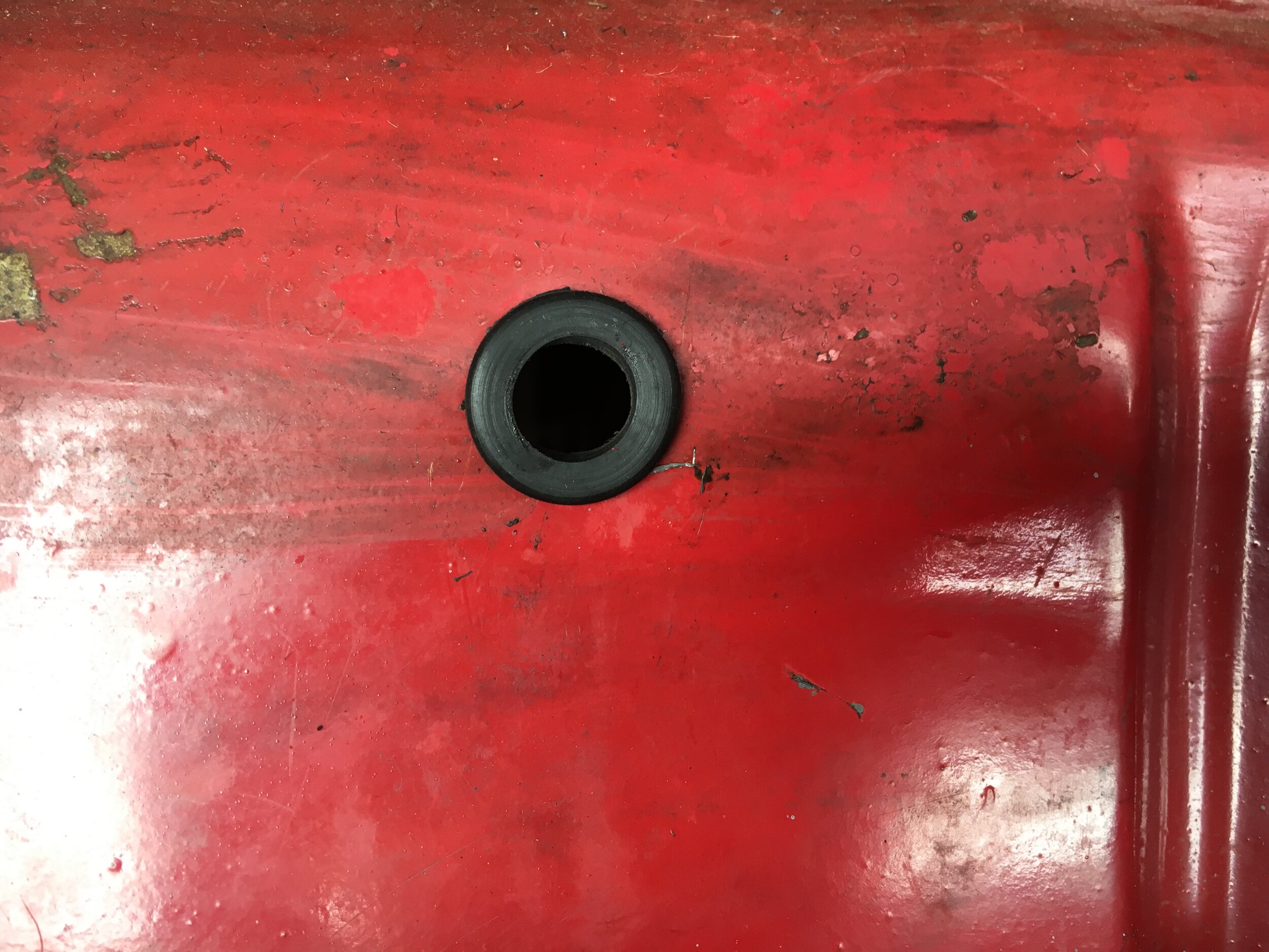
You may wish to repaint the exposed metal edges to retard rust (not a concern in northern-central New Mexico). Then, slice some fuel/vapor hose and slip it onto the vertical support to protect the intercooler.
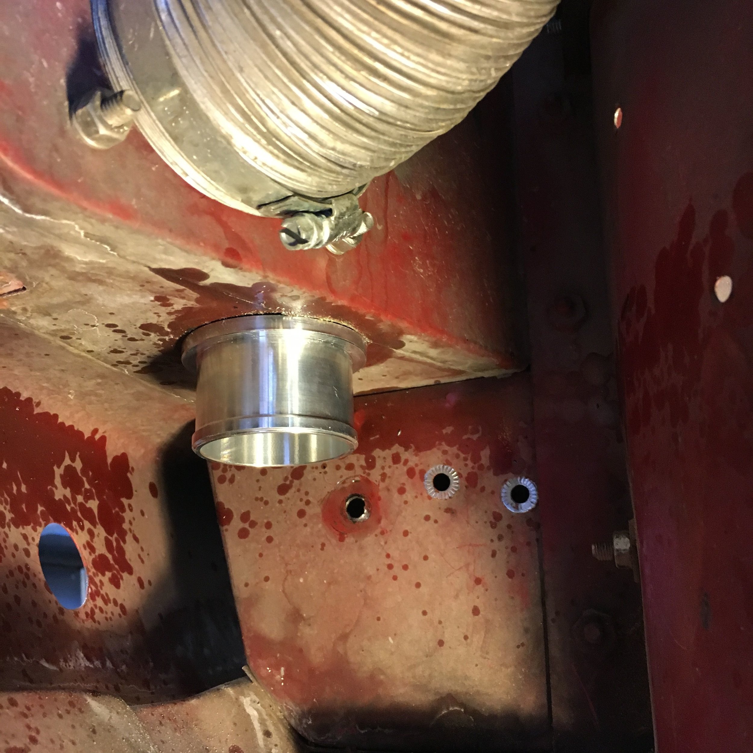
Finally, slip the joiners into the holes. These photos show imported, lathe-turned aluminum pieces, but extruded aluminum nipples are much less expensive and work just as well:
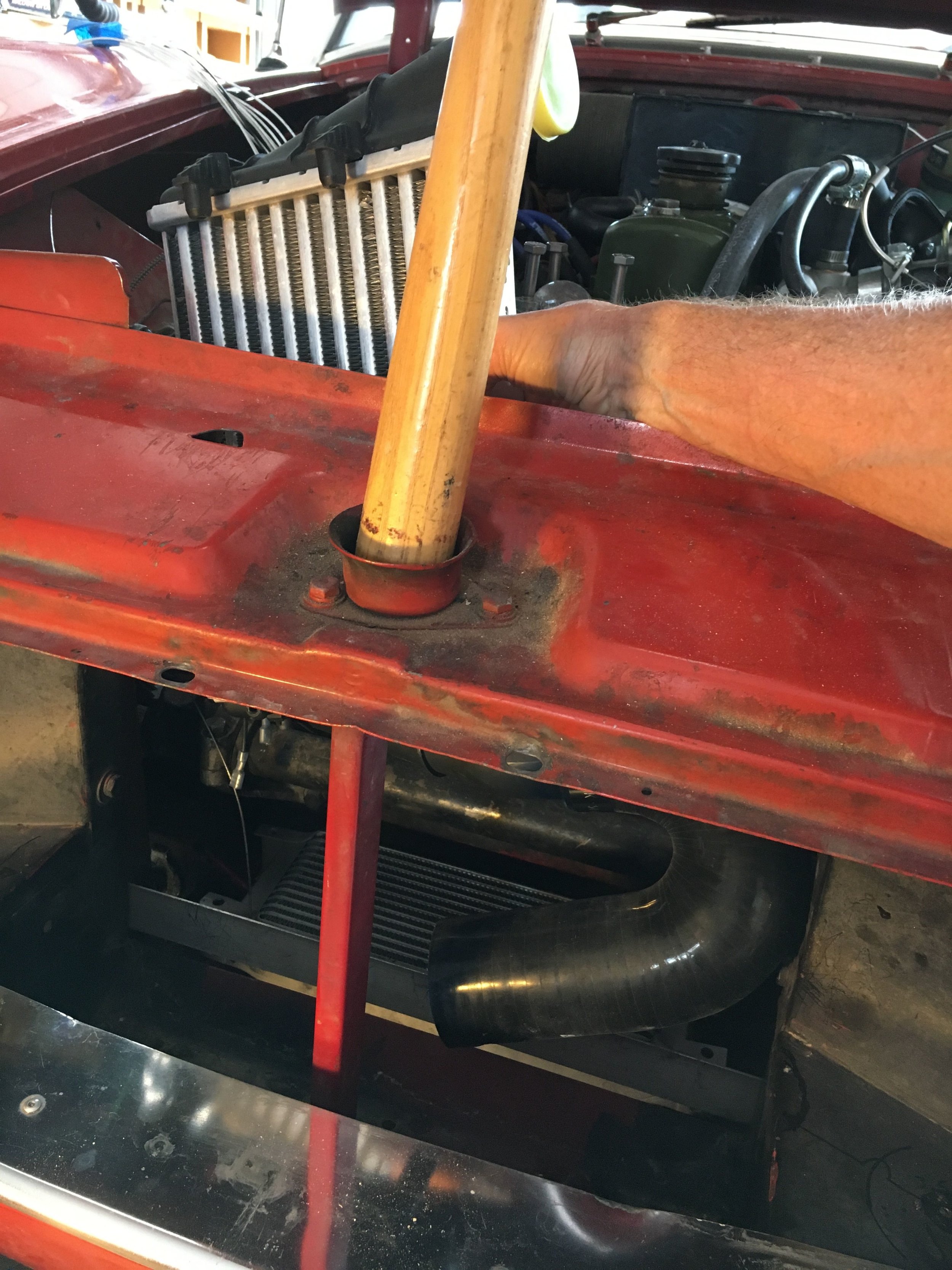
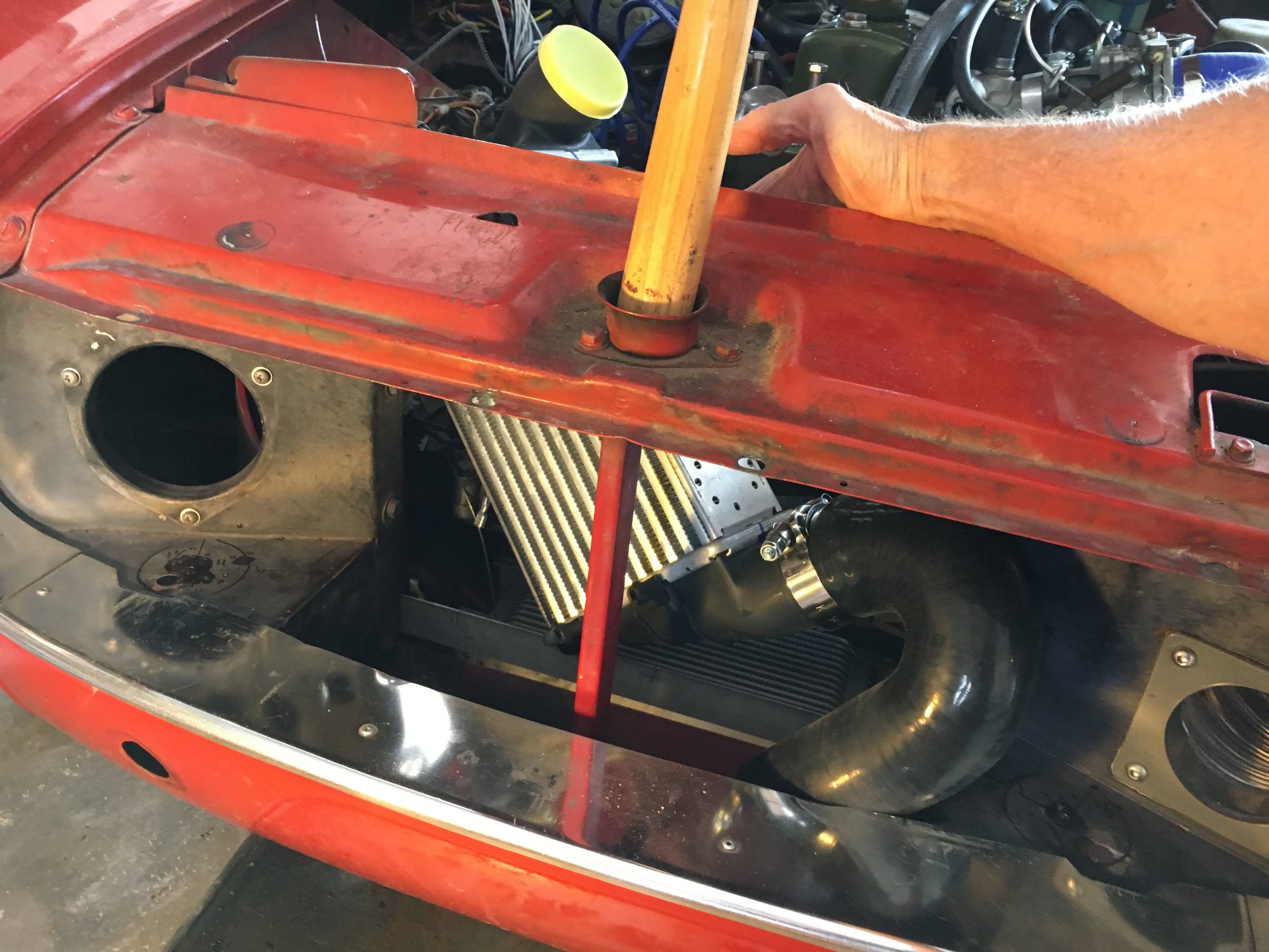
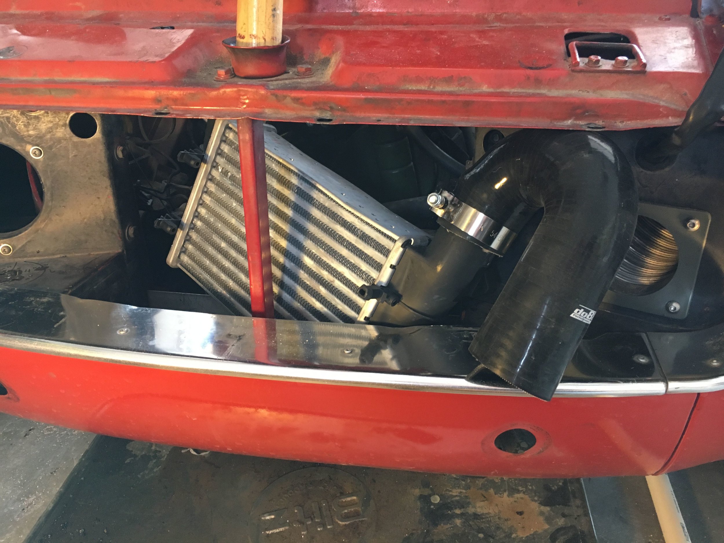
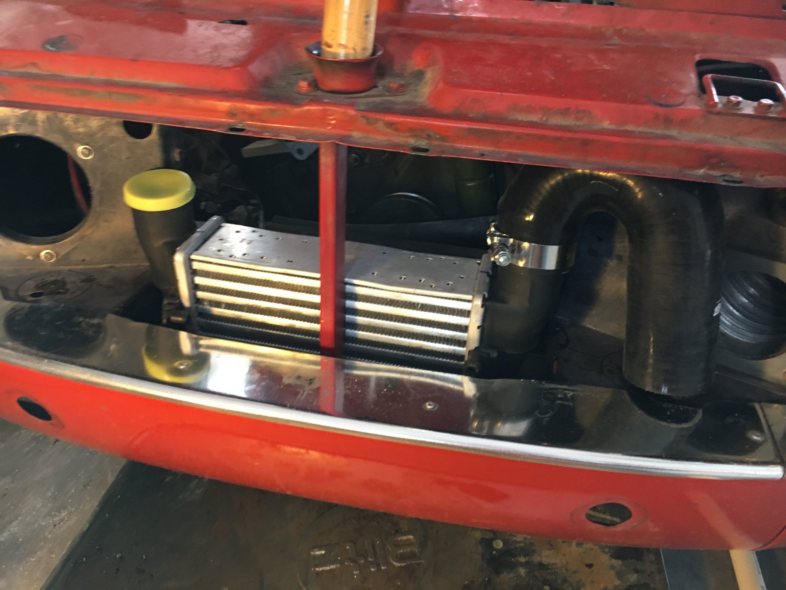
STEP 3 - Install the intercooler
Installation is straightforward, as seen in the next photo series. The only decision is whether to attach one hose before working the intercooler into place, or to install both hoses after the unit is slipped into the well. We recommend experimenting with just the intercooler itself first. Using a water-based lubricant liberally on the plastic nipples is a big help when installing the snorkels.
You may choose to place a piece of thin rubber beneath the intercooler, but the core is tough and will not be subject to much vibration:

STEP 4 - Modify the Grille Mounting Tabs
The intercooler will not foul the OEM grille, but you may have to modify or forgo using the lower two mounting tabs, as the holes for their mounting screws were eliminated by the snorkel holes.
The second photo below shows the lower mounting tabs bent upward to clear the snorkels (there was no indication that the grille was any less secure:

If you will be driving your car before completing the project, you may wish to cap off the intercooler. While tape will work perfectly well, these flexible PVC caps are also available:

Modify the bumper brackets
Although you may elect to cut a slot in the lower valance panel to maximize intercooler efficiency as shown in the following section, many states require a front bumper—and the slots may be obstructed.
If you prefer a ‘stealth’ installation or just want to retain the stock bumper, the Audi A4 intercooler will still reduce intake temperatures by as much as 127.8 F. However, the bumper brackets will require slight modification to clear the intercooler snorkels.
We used an inexpensive rotary carbide bit to create a relief in the brackets as shown in the below slideshow, but a half-round file works fine. The first image shows the issue, while the other images show larger and smaller reliefs required on each side:

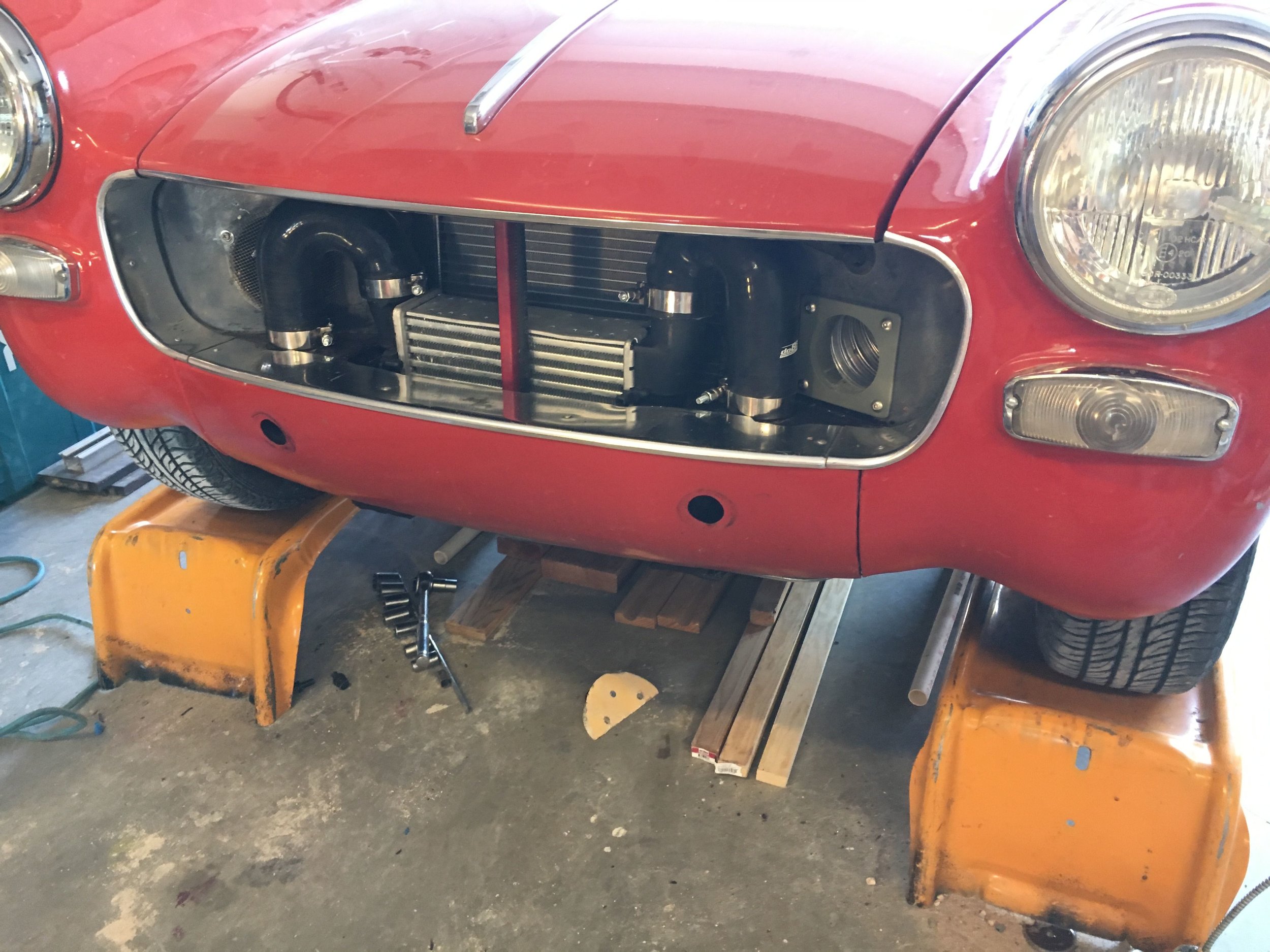
Here is the finished result—a ‘stealth’ intercooled, supercharged powerplant hidden behind a stock grille and bumper:
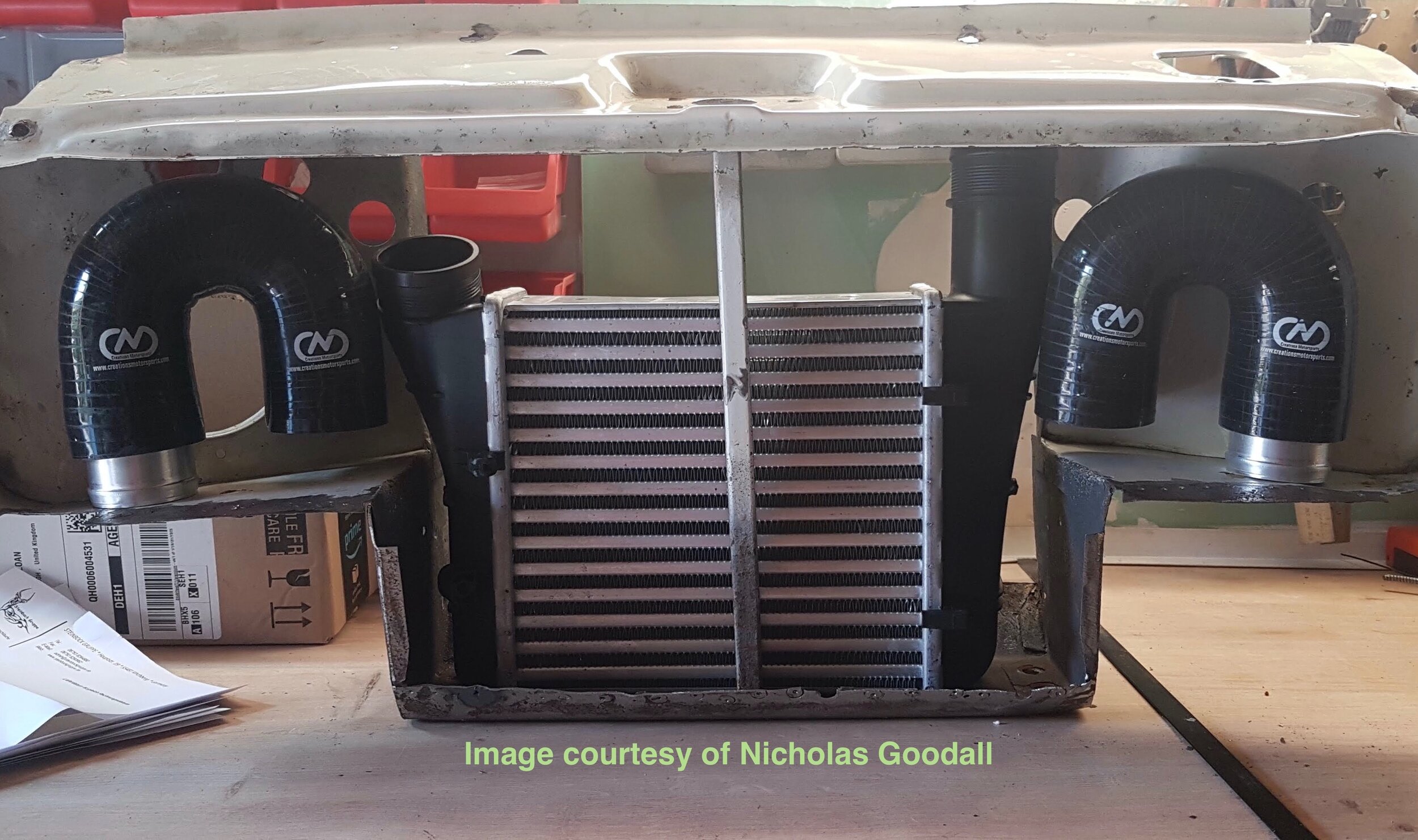
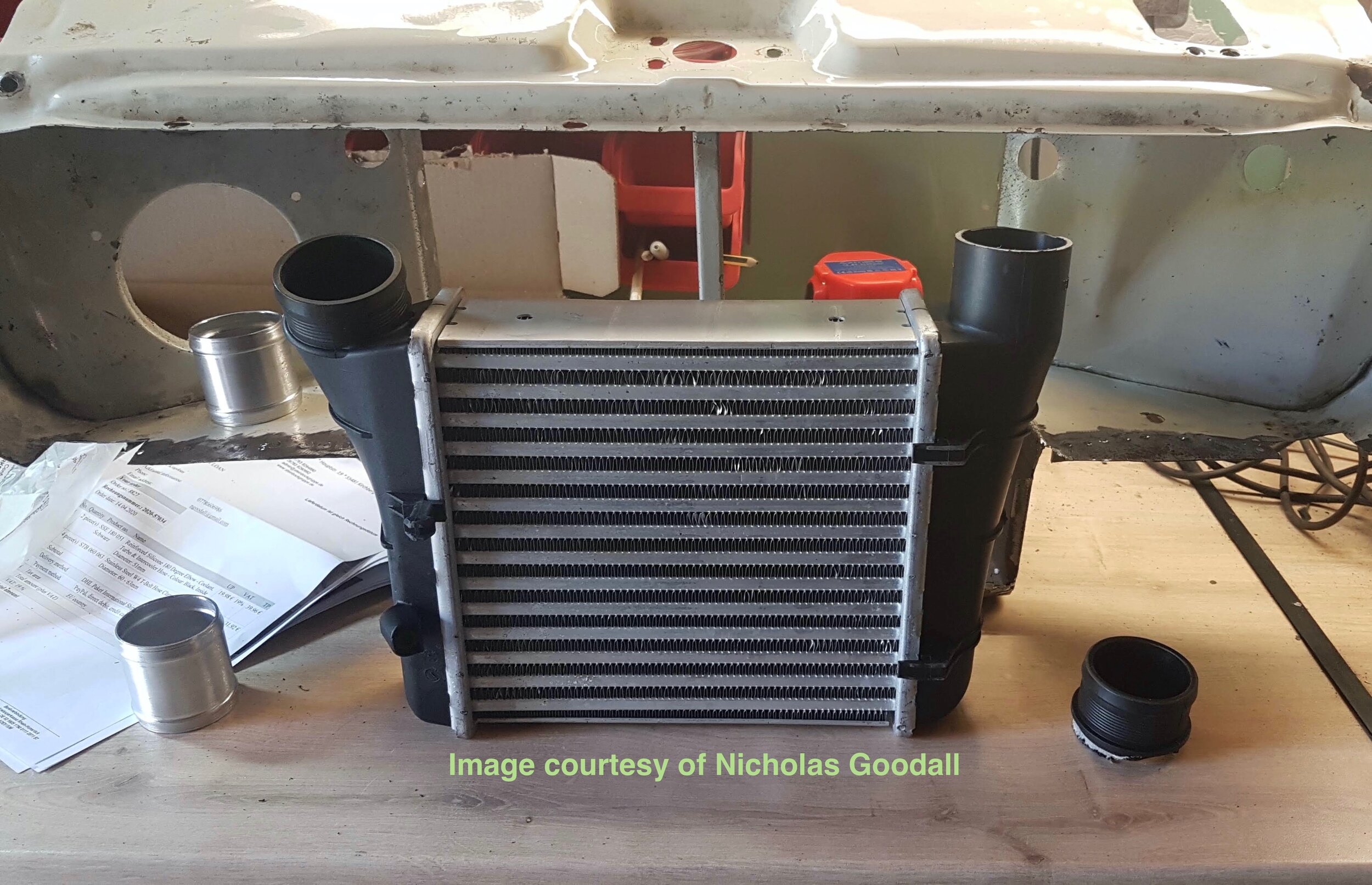
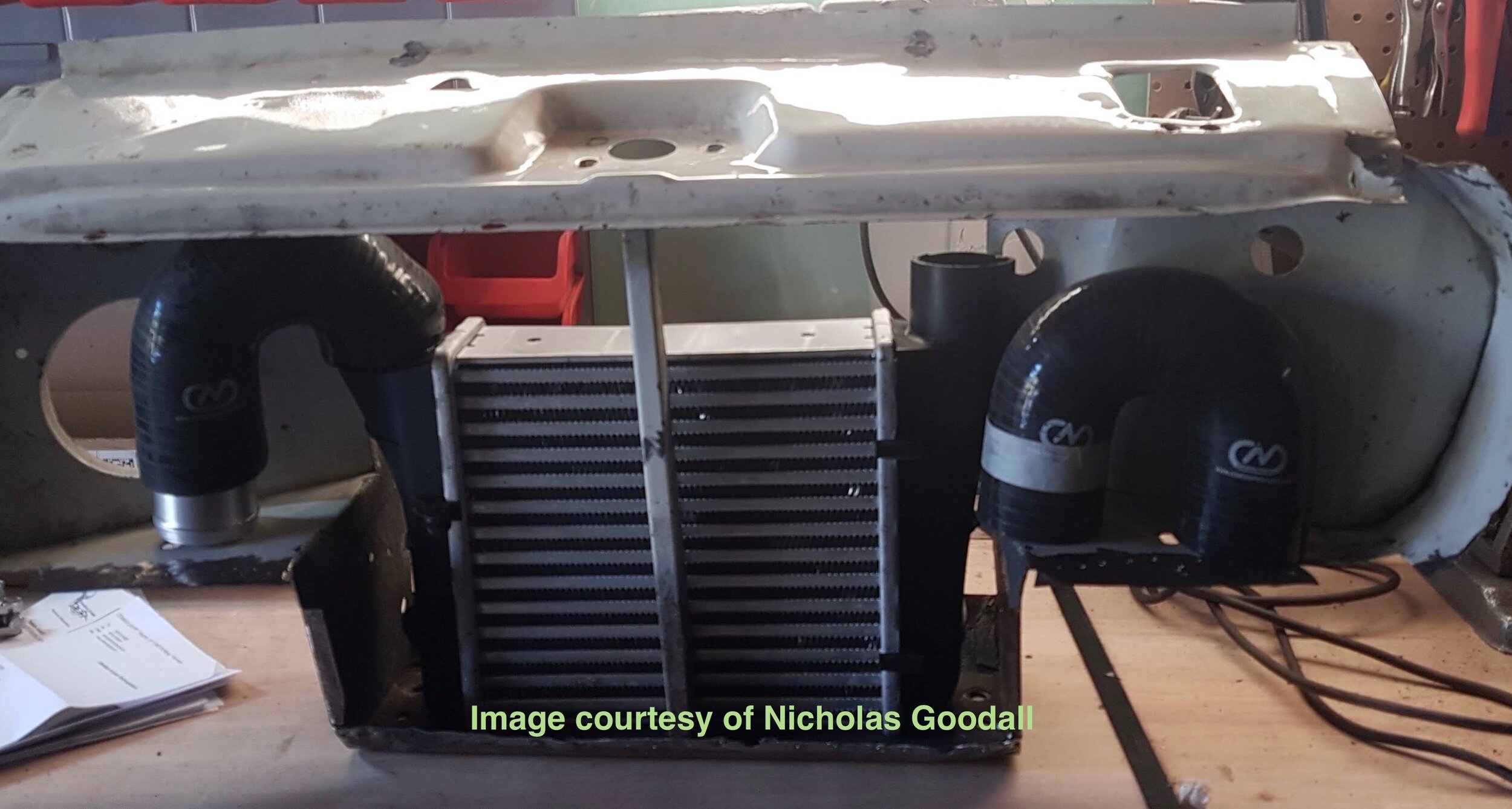
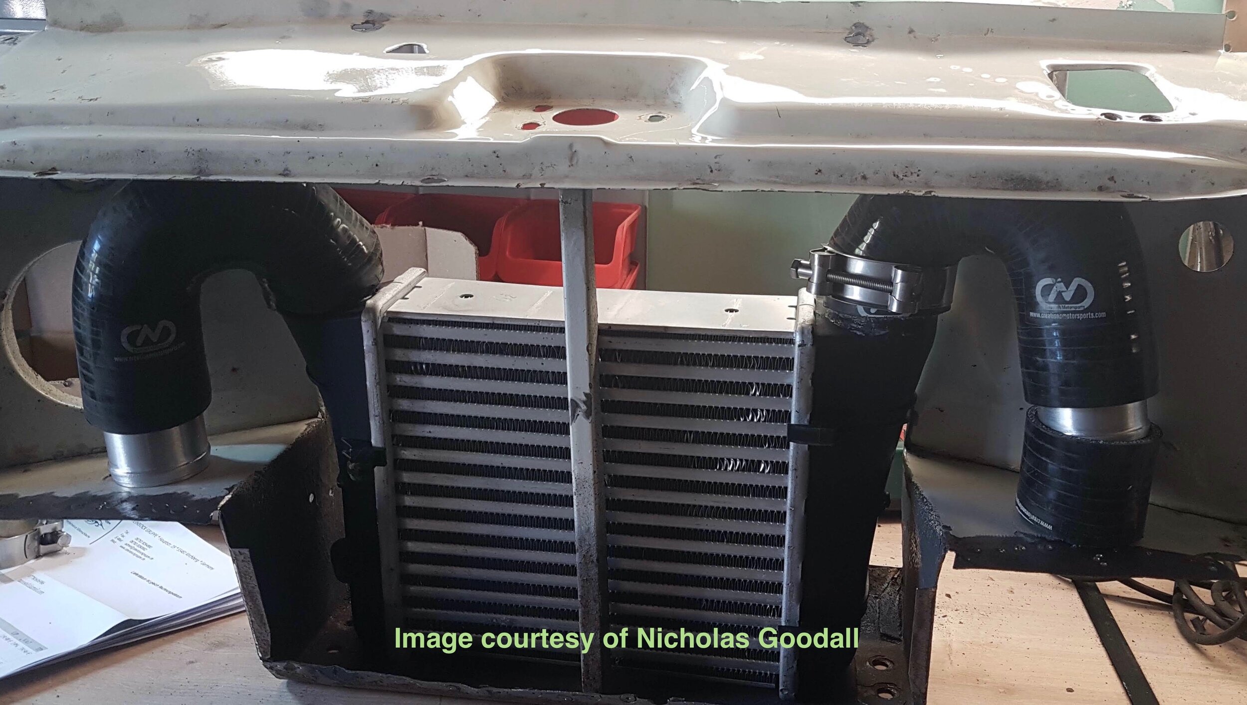
morris Minor intercooler
The Morris Minor has different space constraints. Although we do not have a Moggy in the shop, here are a few images of an outstanding example from Down Under detailing one solution:
![image1[3] (1).jpeg](https://images.squarespace-cdn.com/content/v1/543af5a2e4b039cd17f66c87/1672419986764-KG2IZLXBCTCP5SXC0OUQ/image1%5B3%5D+%281%29.jpeg)
![image0[3] (1).jpeg](https://images.squarespace-cdn.com/content/v1/543af5a2e4b039cd17f66c87/1672419992144-NBIG0GWQZ9ARVRBH8N65/image0%5B3%5D+%281%29.jpeg)
![image3[2] (1).jpeg](https://images.squarespace-cdn.com/content/v1/543af5a2e4b039cd17f66c87/1672419995960-A70V3PHJ0J17FX7QUIUM/image3%5B2%5D+%281%29.jpeg)
Paul searched for the smallest intercooler he could find, with a core size of 450x140x50mm. He anticipates having to do a bit of panel-beating on the grille to make it fit, but it certainly looks right at home in these images.
We will post photos of the final product and any fitment tips he may have to offer.
install an intercooler intake & grille
In order to increase intercooler efficiency, you may wish cut one or more holes in the sheet metal below the engine radiator opening to direct cool air onto the lower 60% of the core that extends down into the well where the horns used to reside.
You may configure the slots however you wish, but we recommend a cumulative area of at least 60% of the core’s frontal area.
As an example, we have designed a bespoke 6061-T6 aluminum grille to fit just beneath the engine radiator opening whose design cues echo the OEM grille and compliment the car’s aesthetics:

At present, we do not have immediate plans to produce these grilles but welcome Spridgeteers to make use of the drawing for personal use.
reroute the heater fresh air intake
Retaining the heater and fresh air ventilation system is not difficult with this conversion. However, on early cars like the 1967 MG Midget in these photos, the OEM fresh air intake for the heater/ventilation system must be rerouted, as the supercharger mounts directly in its path.
The method is straightforward: simply remove the OEM duct, air control vane, and snail-shaped fan, and either relocate or replace each component.
These instructions utilize large diameter silicone hose and metal connectors, but the cost can be reduced (together with the weight) by using aluminized HVAC duct between the fan and air control vane. That said, one upside to the more expensive silicone hose is that it will not conduct heat if you wish to use the system for fresh air ventilation instead of merely heating the cockpit.
The inline fan shown here, an aluminum racing model from Revotec (available in either 3” or 4”), can also be replaced with an inexpensive plastic marine bilge fan to save still more money. The 4” Revotec auto racing fan shown here moves a lot of air, looks nice, and is very light but is also expensive (though often cheaper if purchased directly from the UK):

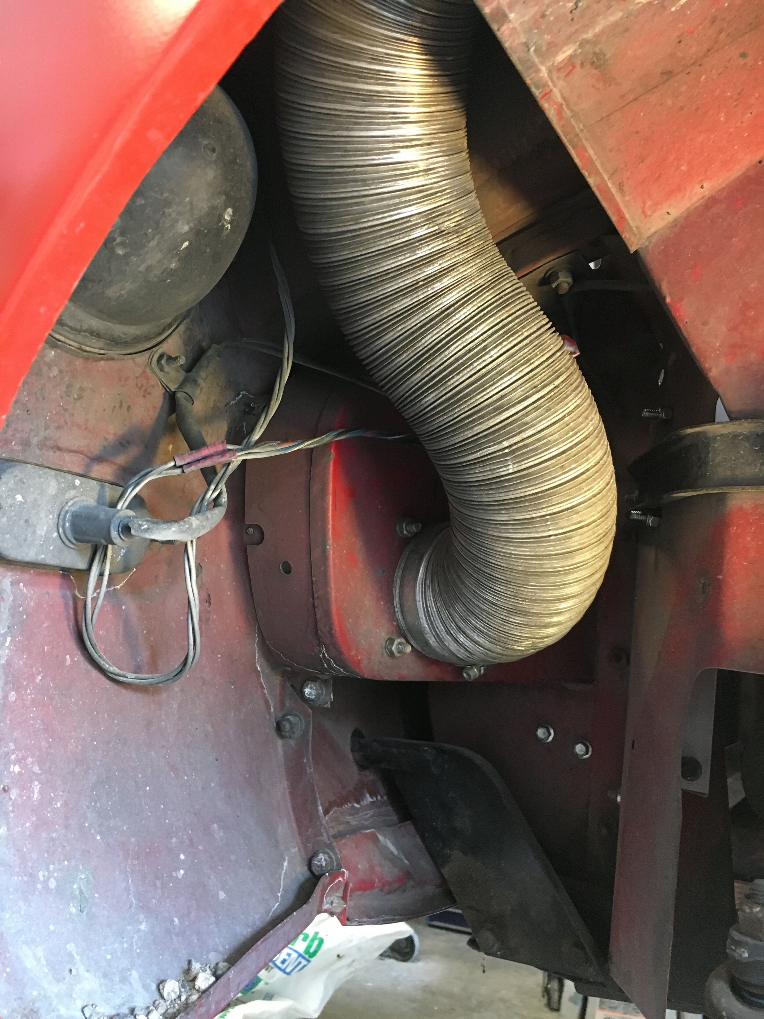
After removing the OEM duct, air control vane, and fan, assemble the fan and silicone reducing connectors and elbows and metal nipples (these are steel, though aluminum would be much lighter) to produce the following configuration:
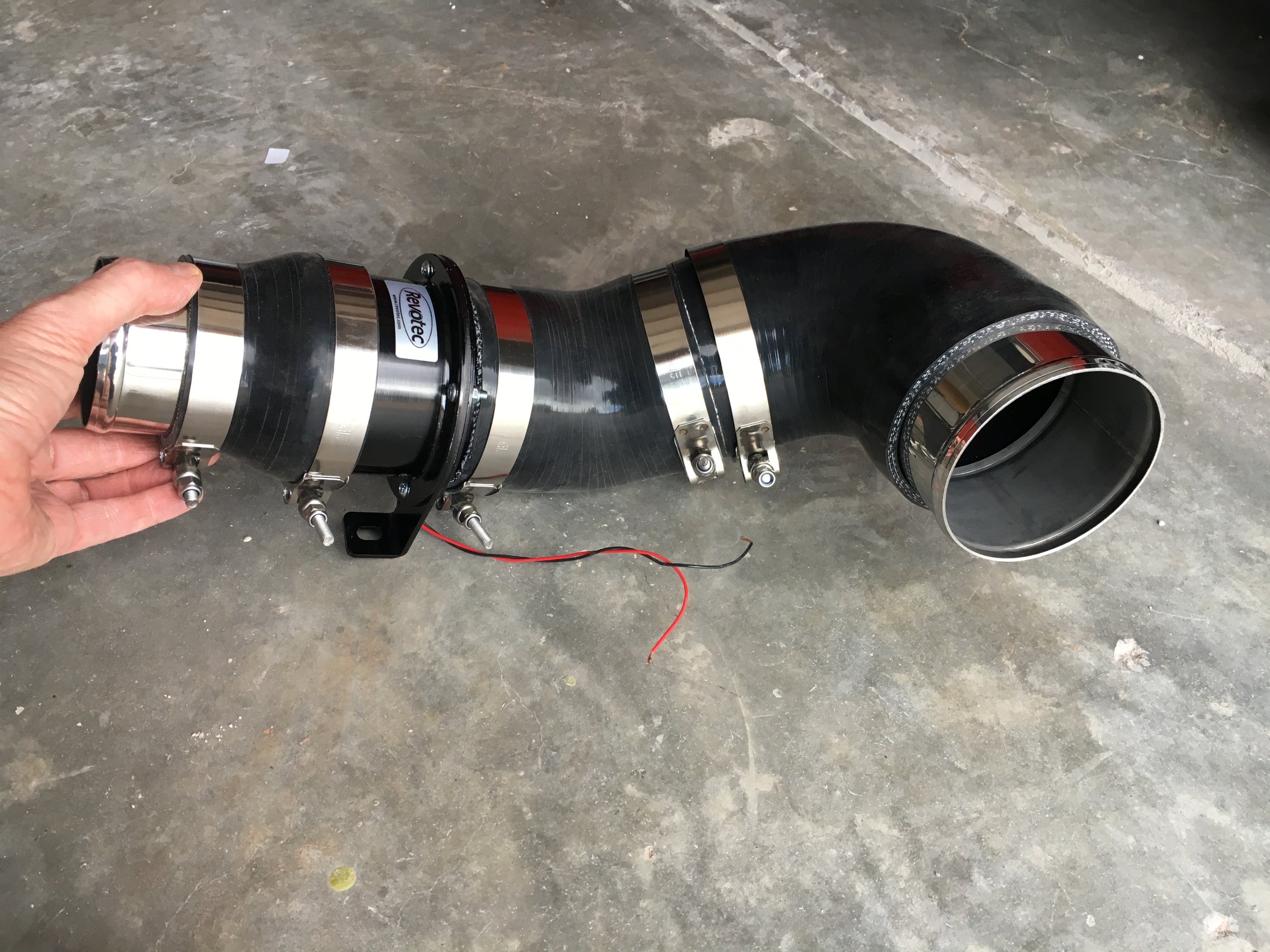
The above shows a 4” fan and duct toward the heater box with a 4” to 3” inline reducer aiming forward toward the front sheet metal, because that is the largest duct that will fit between the inner and outer fenders:

Affix the fan’s legs to the wheelhouse sheet metal, keeping in mind that nuts and lock washers should go inside the engine compartment to avoid frozen fasteners down the road.
Next, the fan assembly is connected to the OEM air control vane—moved by the shortened and dramatically smoother-operating OEM cable (we positioned the lever atop the affair as shown below). The air control vane is connected to the heater box by a 4” to 3-1/4” inline silicone reducer:

The insect mesh that originally mounted directly to the OEM fan on the 1967 MG Midget shown here is moved up to the front sheet metal, to allow room for the intercooler snorkel. An aluminum or steel trim ring would make for a less spartan installation than shown here, which simply uses washers to grip the mesh:

Now, trim at least 1” or more from the larger leg of a 4” to 3” silicone reducing elbow—and be extra careful when using a razor knife:
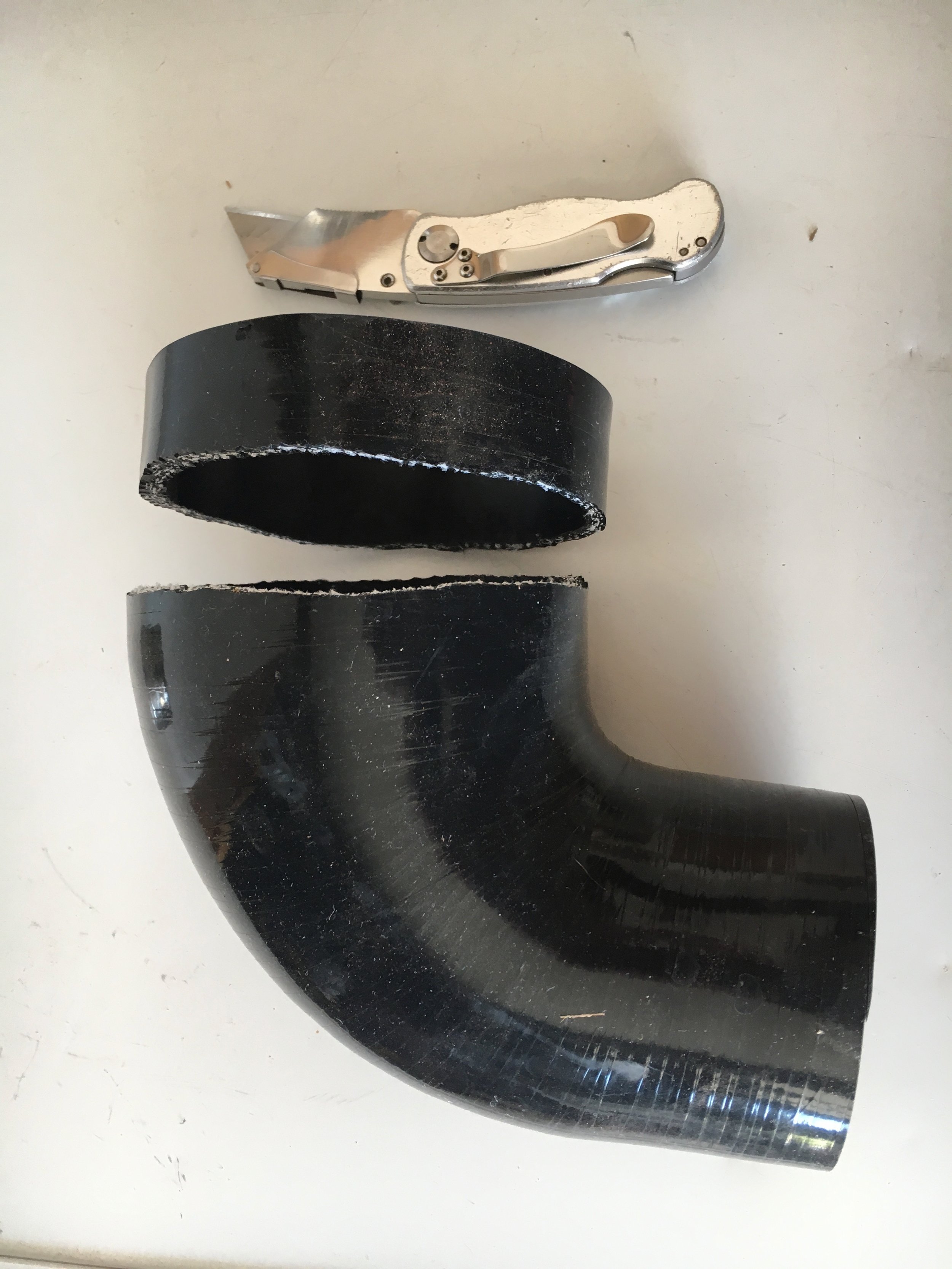
This will allow the elbow to clear the right-hand tank of the dual-pass 1979 VW Rabbit radiator shown here, or the angled sheet metal piece that connects the radiator supports to the right-hand inner fender (or wheelhouse) if you are running an OEM-sized radiator:

Next, trim the flared portion off one end of a connector nipple, as the aluminized HVAC duct is too inflexible to attach otherwise. We used a Dremel with a cutter wheel and held the nipple by clamping it into the silicone elbow, then securing the hose clamp in a bench vise (just loosen the clamp to rotate the nipple as you go):

Be sure to protect your eyes and lungs when performing this operation. Ideally, a full face shield is better than just goggles when using cutoff wheels of any kind. Don’t forget to break the edges on the nipple after using the cutoff wheel.
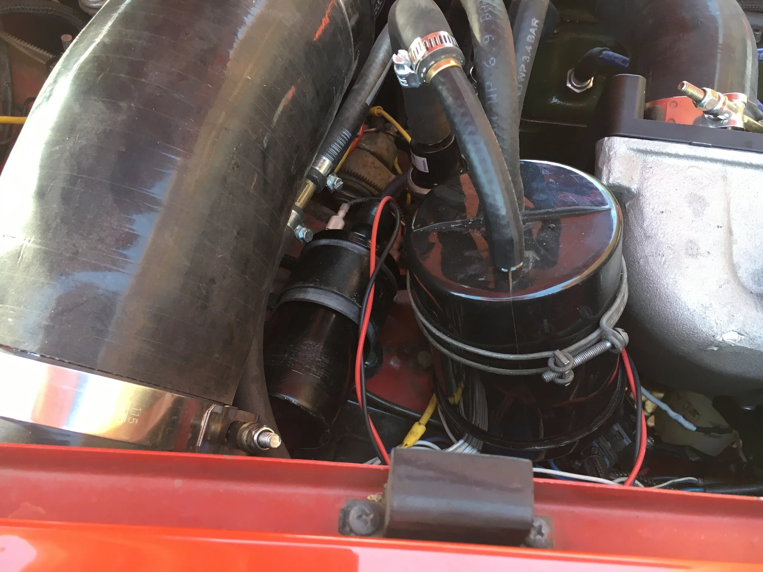
Here is the affair attached to the OEM sheet metal flange. The 3” aluminized duct hanging down at the right-hand edge of the photo is threaded up inside the fender and attached to the Revotec’s inlet:

Loosen the hose clamp on the larger leg slightly and rotate the elbow upward toward the natural path of the aluminized duct, then work the duct onto the nipple and tighten all of the clamps.
You can see in the next image that we found a standard clamp best for the narrow flange pressed into the OEM sheet metal, whereas T-bolt style clamps worked better for both ends of the modified nipple:

Finally, as discussed in a later section on plumbing the blower’s intake snorkel, you may have to remove the OEM heater shut-off tap and screw an NPT nipple into its base plate to gain clearance. We then installed a brass inline ball valve in the heater’s outlet hose—which does not change the function of the shut-off:


relocate the ignition coil
The placement of the OEM ignition coil will contact the underside of the supercharger’s inlet chamber, but this is easily remedied. Here are two options, but ultimately you may place the coil wherever you like.
If you have re-routed the fresh air intake as set forth in the preceding section—and if you are not installing a vapor recovery canister—you can bolt the coil to the existing 5/16-24 threaded holes in the passenger footwell, as shown in the following photo. (The device fitted to the original coil mount is a GM ignition module for an EFI project.)

If you have re-routed the fresh air intake as set forth in the preceding section—and you are installing a vapor recovery canister—the coil will have to go elsewhere.
One possibility is to attach the coil's band mount to one of the two threaded holes used in the above photo, then rotate the coil 90 degrees as shown in the next photo. After a lengthy test drive, one bolt proved sufficient to hold the coil in position:
installing a high-pressure fuel delivery system
A blow-through system requires you to modify the standard-spec SU HIF44 shown in these instructions to operate under boost, which is easily done as discussed here, or you may purchase an MG Metro Turbo-spec HIF44.
However, you must also convert to a high-pressure fuel delivery system, because in the modified HIF44, the boost from the supercharger will be communicated to the float chamber. As a consequence, the fuel delivery pressure must exceed the base requirement of 3 psi by the level of boost you elect to run.
Therefore, you will also need: (i) a high-pressure fuel pump; and (ii) a ‘rising rate’ fuel pressure regulator connected to a return line routed to the main fuel tank or filler neck (to avoid having to remove and modify the tank). See the parts list for examples and related fuel line and fitting requirements.
In the setup discussed in this section, a third component is added—an aluminum swirl or surge tank—but see below note to Bugeye owners. We include this tank because it receives excess fuel volume, which is immediately available to feed the high-pressure pump. Overflow from the swirl tank goes back into the main tank via the filler neck. This combination provides ample fuel regardless of cornering, acceleration, braking force, angle of climb or descent.
On earlier cars like the ‘67 MG Midget test mule shown throughout these instructions, the OEM 1/4” delivery line may serve as a vapor recovery line to prevent the build-up of pressure in the main tank on hot days and avoid fumes escaping into your garage. Or you may use the balance of the coil for the 5/16” delivery line to fashion a new vapor recovery line if (like the author) you removed the OEM delivery line.
Later cars already have a vapor recovery line coming forward to a charcoal canister mounted in the engine bay.
In either case, see Step 8 at the end of this section for details on vapor recovery to maintain optimum drivability in hot climes.
However, regardless of which option you choose, you can install the high-pressure fuel system and continue to run naturally aspirated, because the ‘rising rate’ regulator will supply the HIF44 perfectly—even modified to run under boost—until you finish the project. Accordingly, the steps in these instructions are in no particular order.
STEP 1 - Install high-pressure pump and swirl/surge tank
This section applies to standard-body Spridgets. Bugeye owners may prefer a smaller swirl tank and high-pressure pump mounted in the engine bay. Morris Minor owners may be able to fit the swirl/surge tank and high-pressure pump in either location.
This superbly finished right-hand drive car uses a combination swirl tank and pump housing designed for the Bosch 044 EFI-spec pump (and in the parts list):
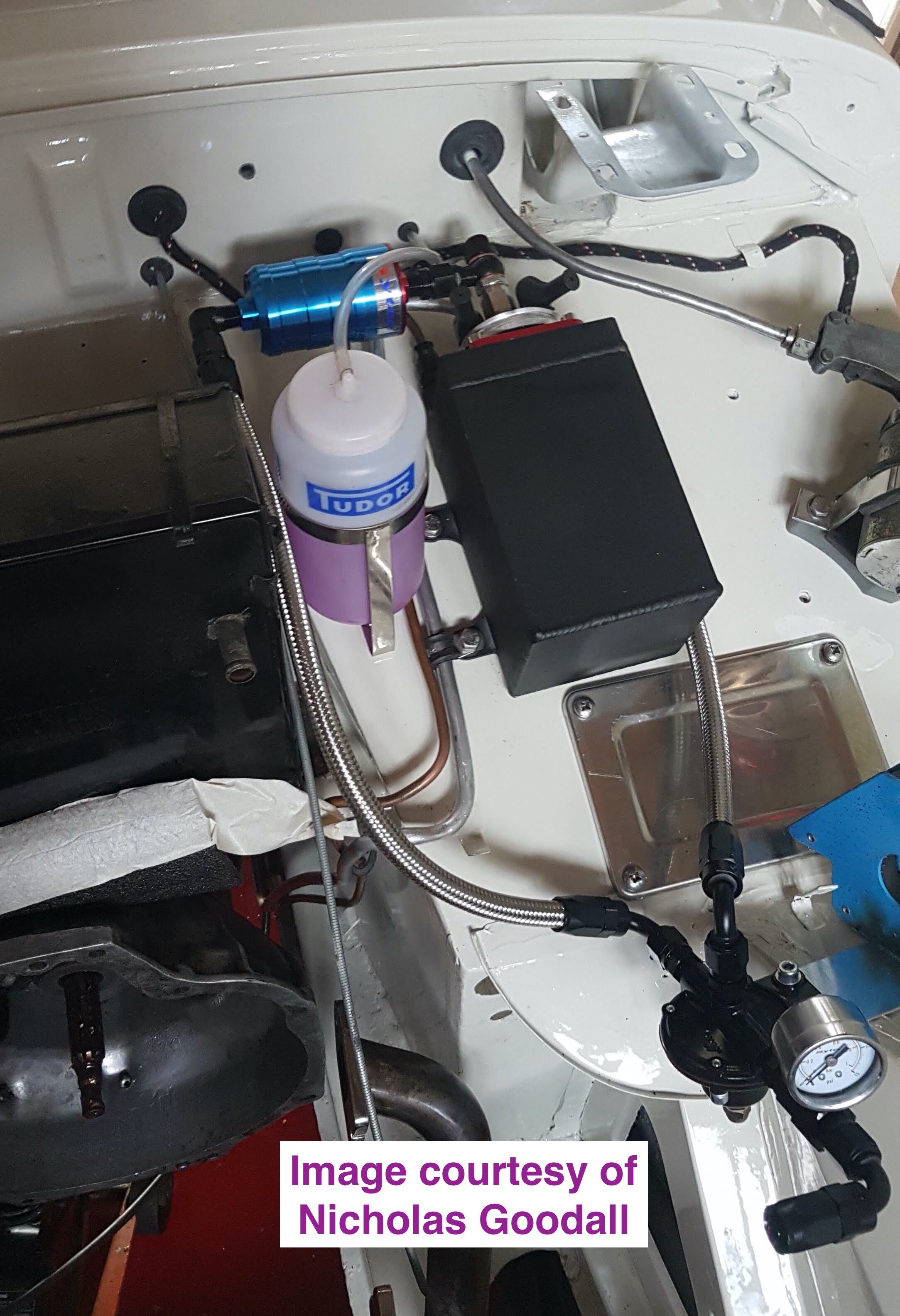
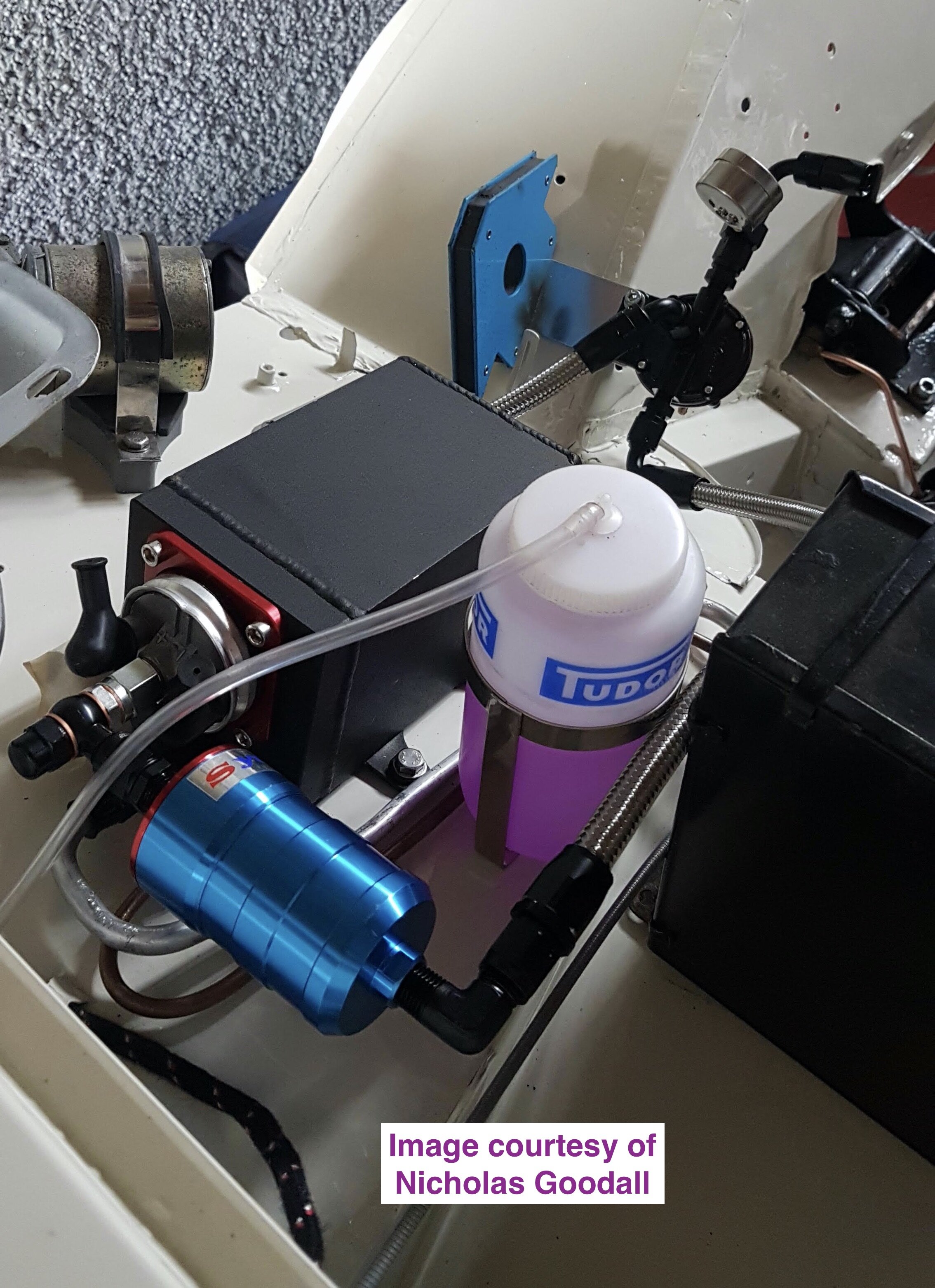
Here is a beautifully finished, standard body Spridget, featuring another integrated swirl tank and pump housing, also designed for the Bosch 044 EFI-spec pump:
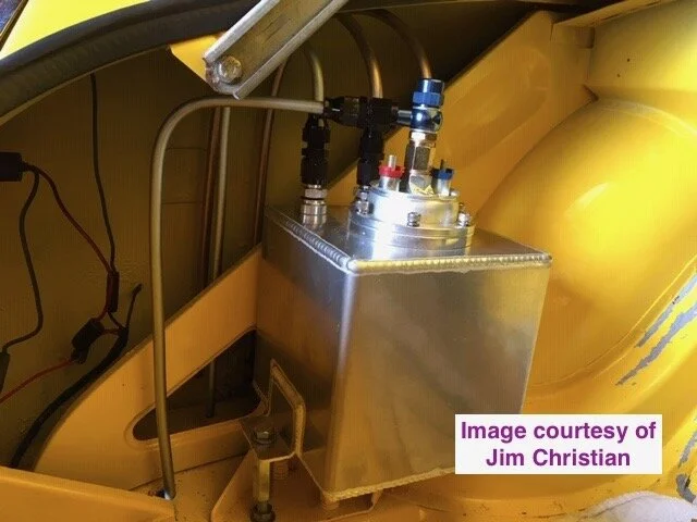
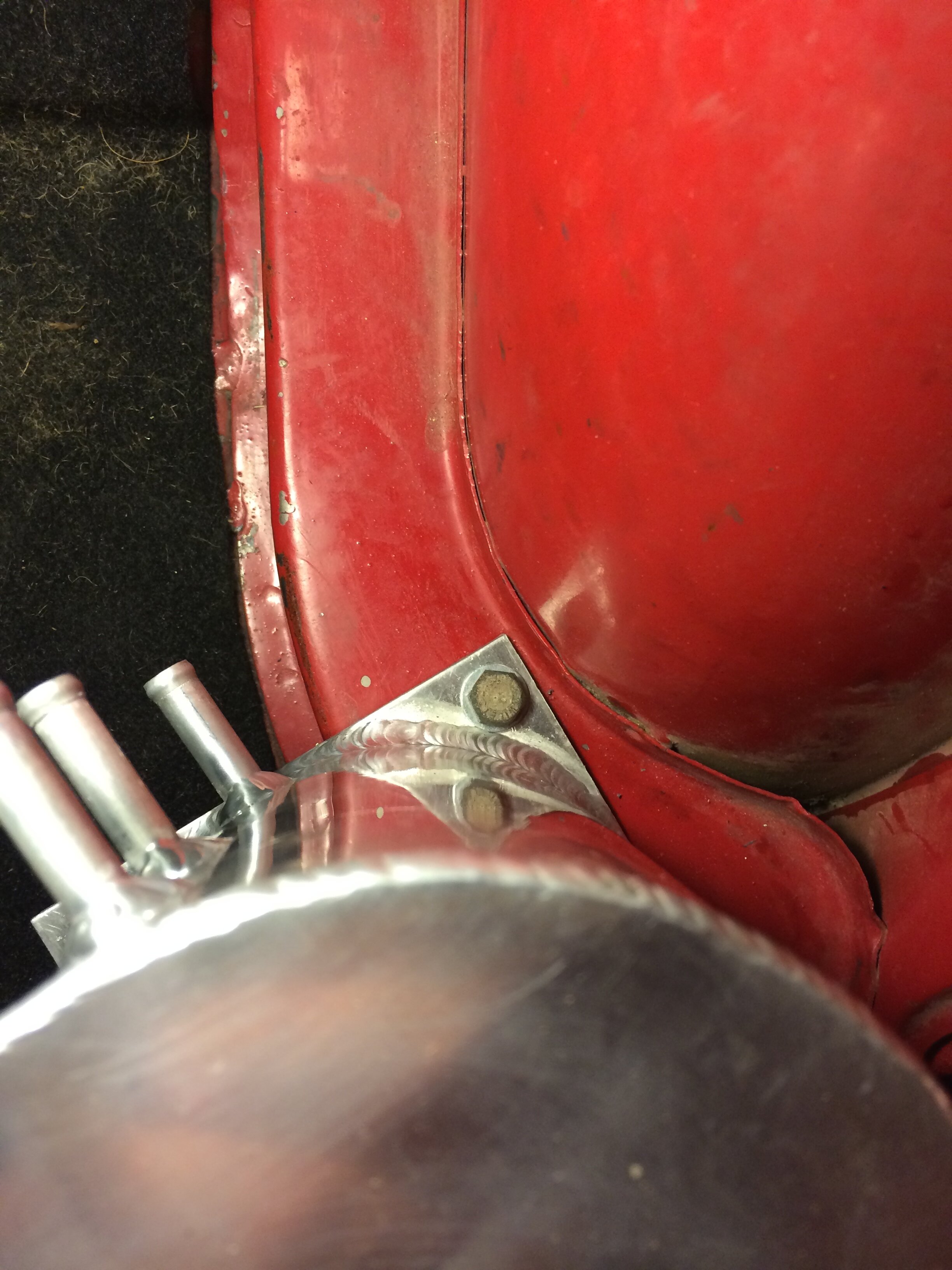
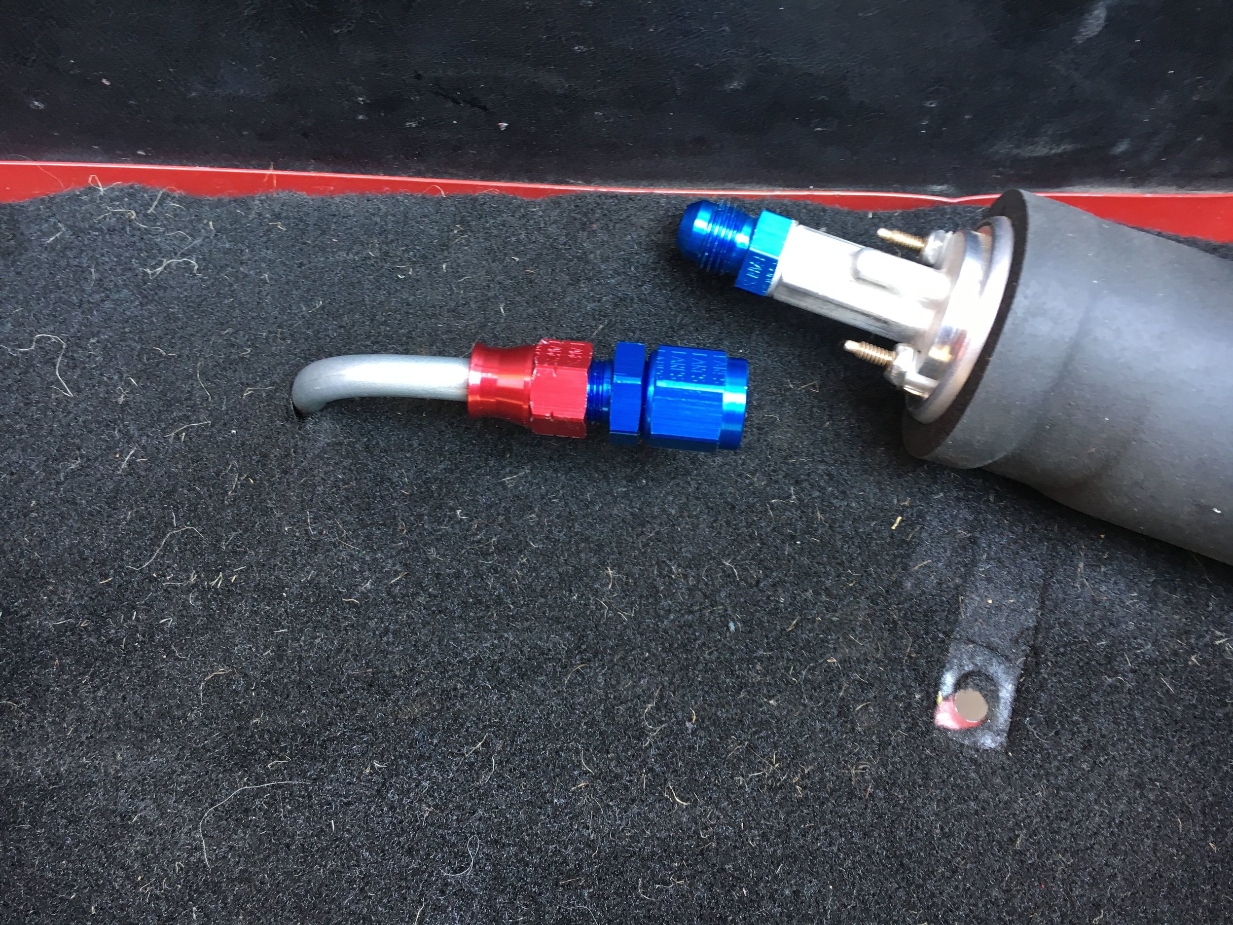
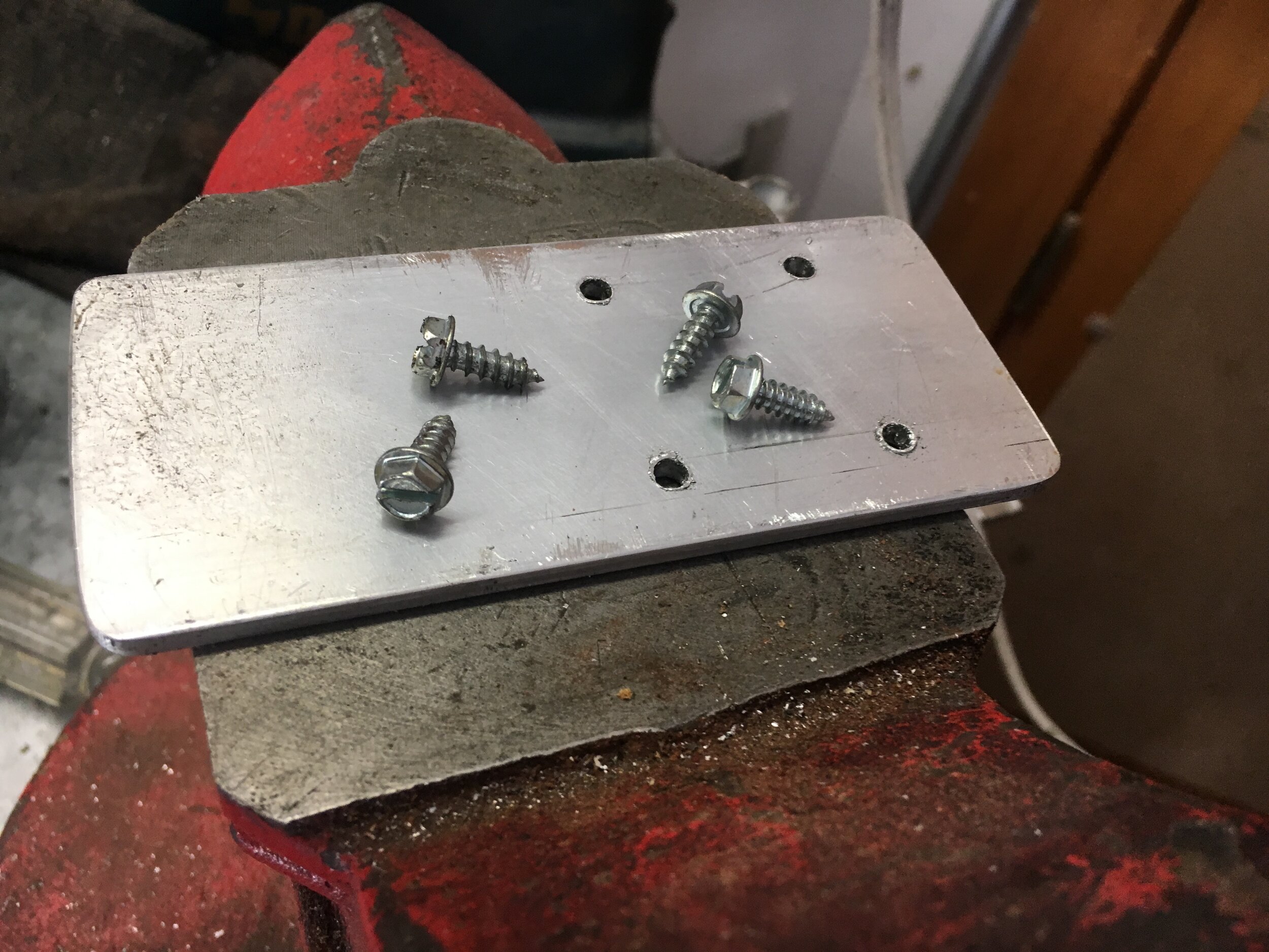
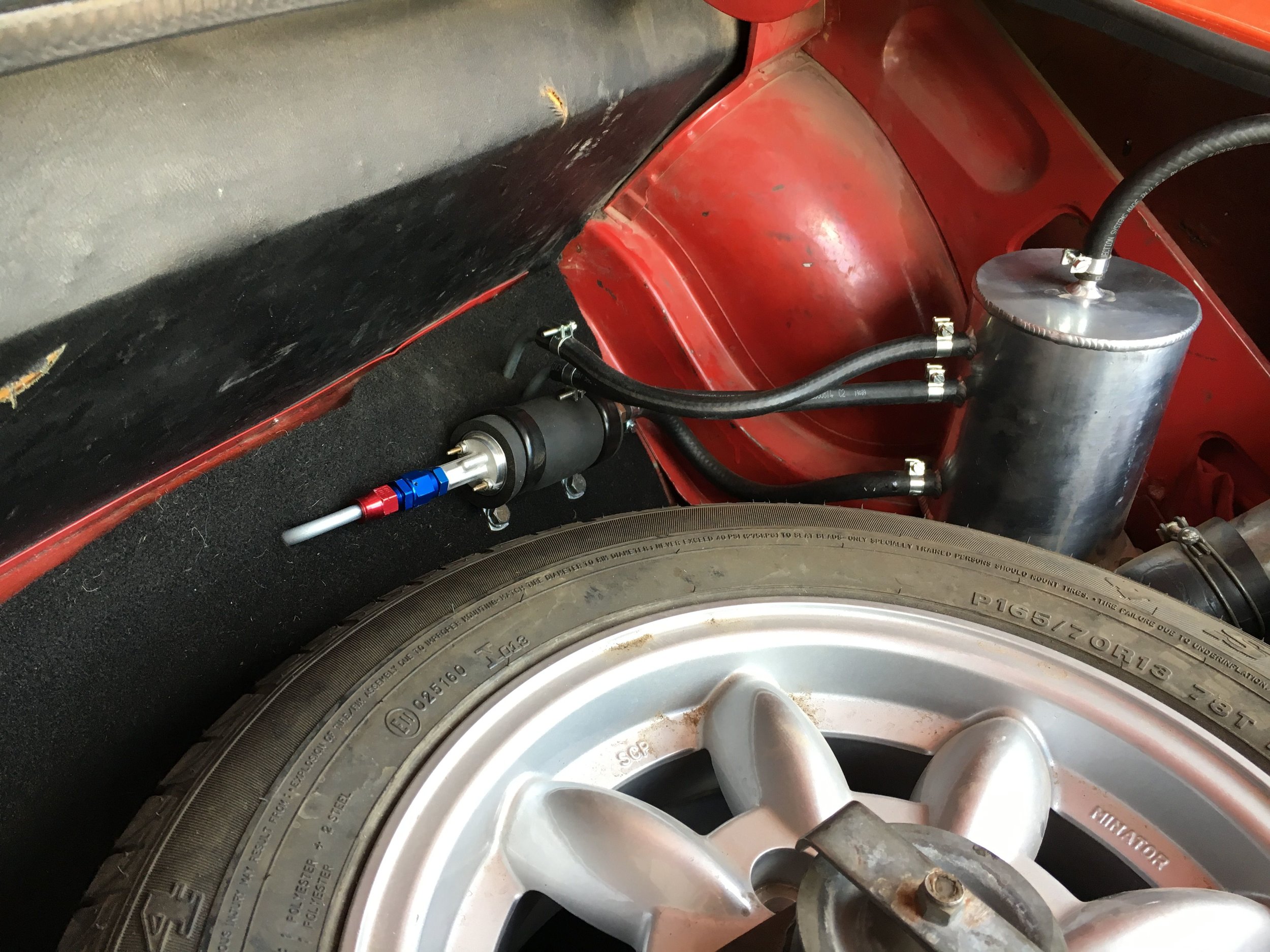
In the author’s more pedestrian ‘test mule,’ a separate swirl tank bolts to the right-hand frame member in the boot, and to a simple dog-leg bracket made from aluminum stock available at your local home improvement store (pictured is an older tank replaced in the parts list by the model discussed in a moment, which features interchangeable fittings):
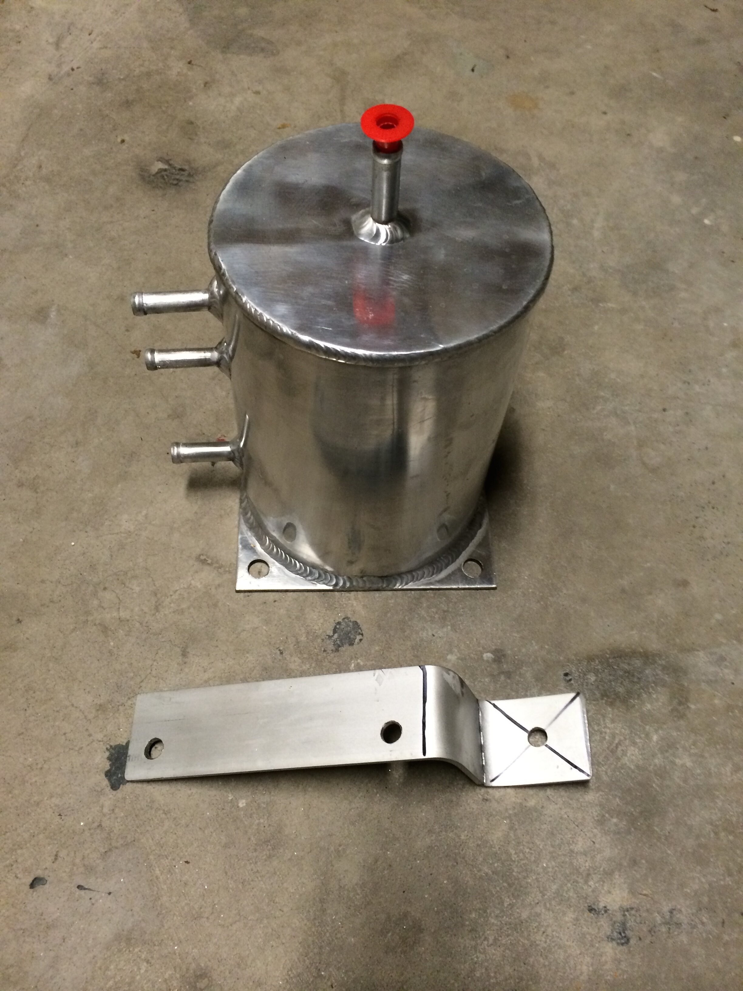
The below unit (in the parts list) is actually less inexpensive than older welded tank we used, and comes with several AN-style fittings and hose barbs, which should be adequate for most systems (though Jegs and others carry myriad such fittings for very little money):

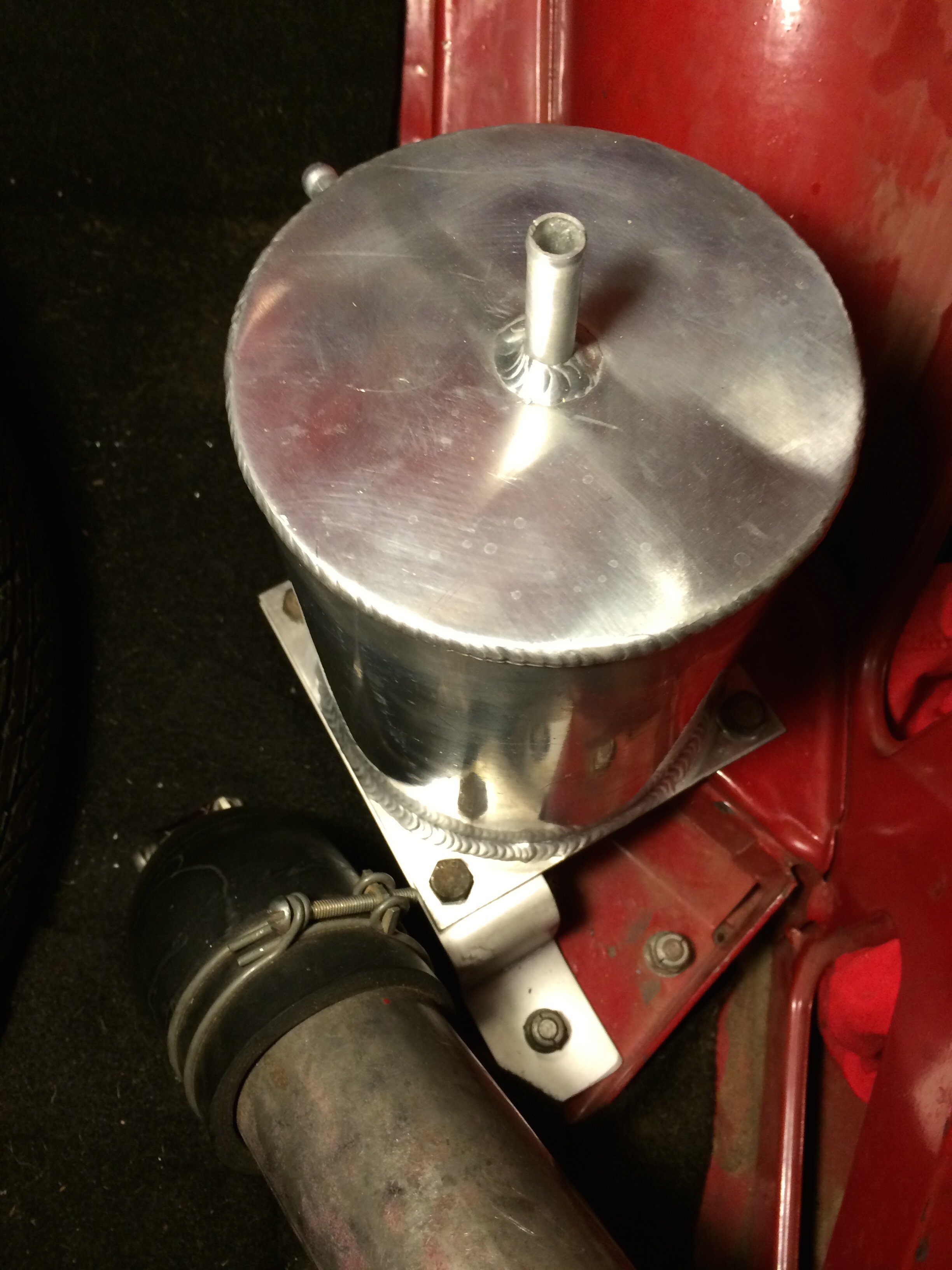
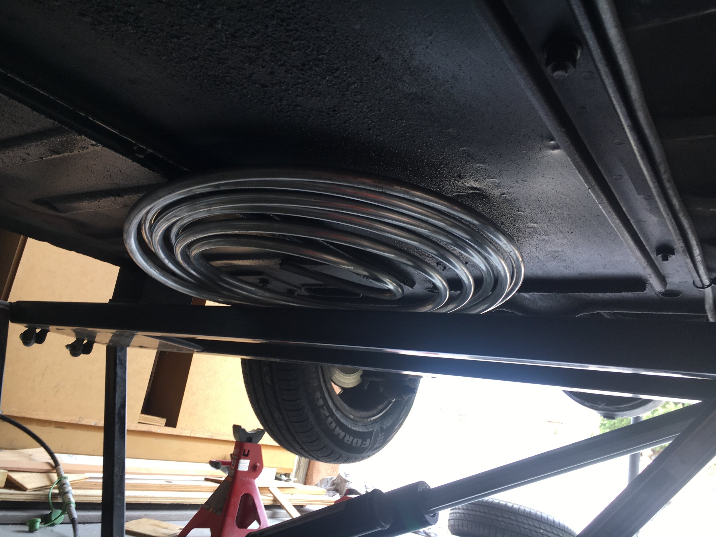
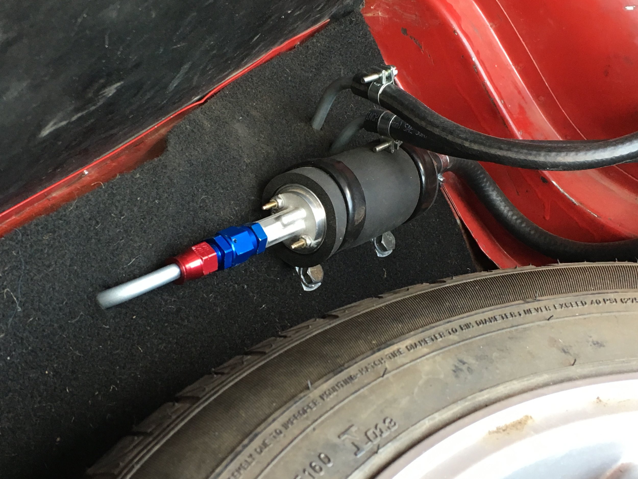
The high-pressure pump mounts in the trunk (or boot) adjacent to the swirl tank, as close as possible to the right-hand frame member to afford room for the spare tire, while allowing for the 3/8" feed line to curve without kinking.
Here is the finished product. Again, this is the old-style tank with welded nipples, but fuel line routing is identical:

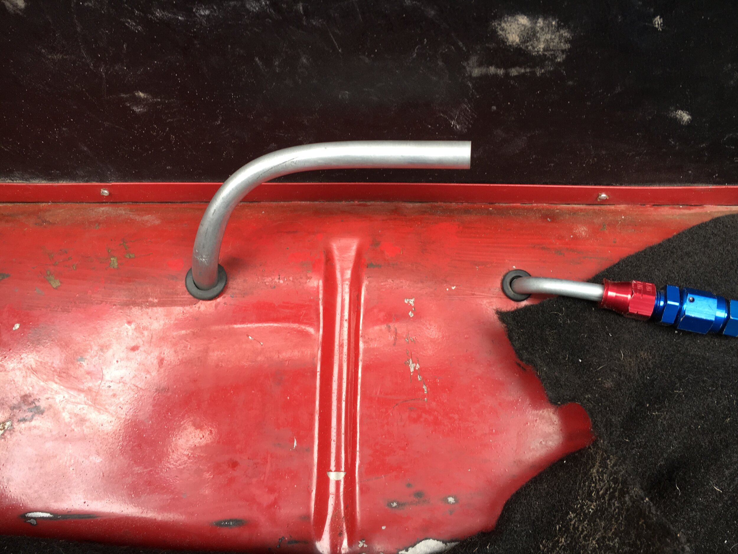
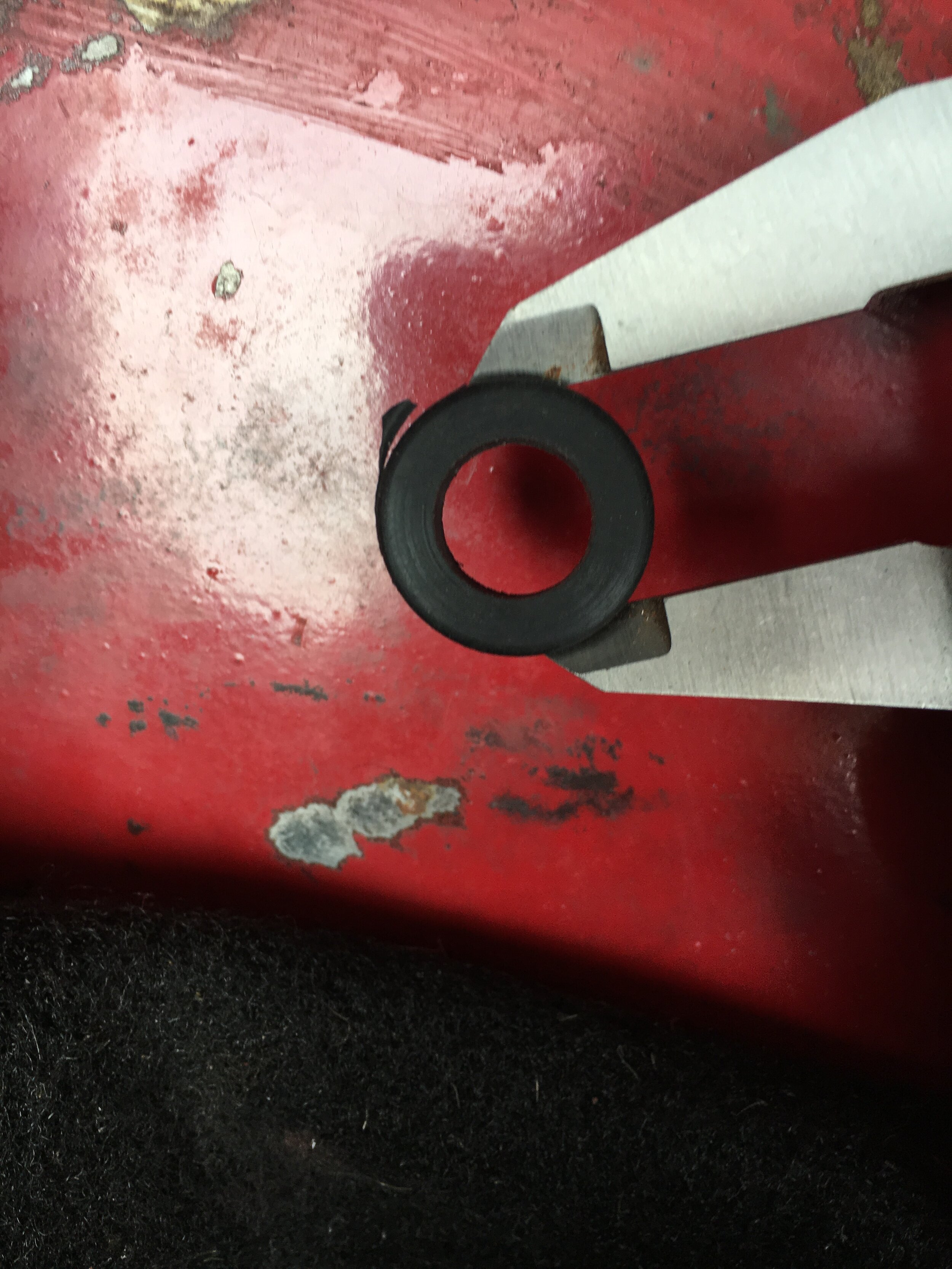
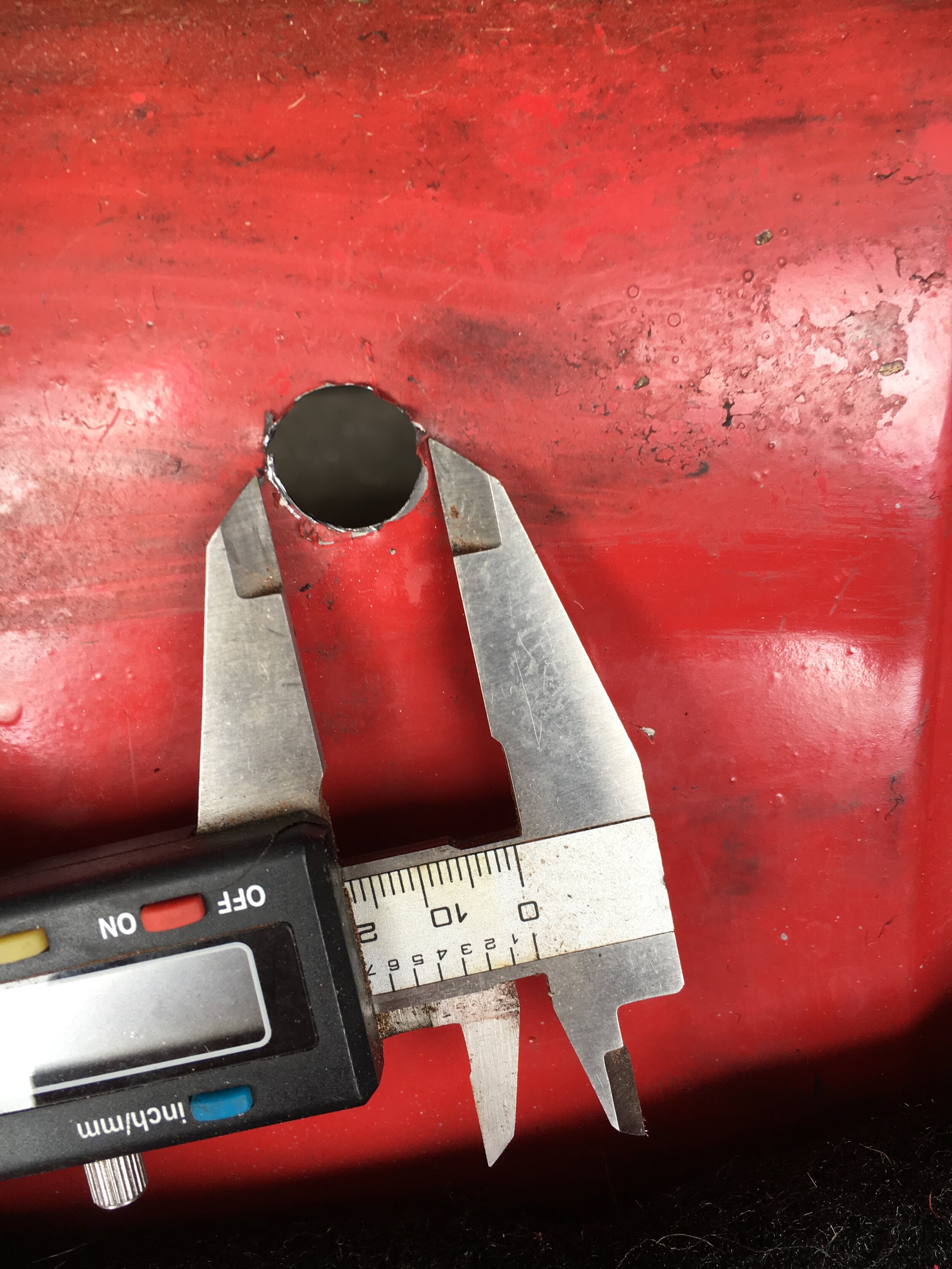
STEP 2 - Drill holes, install grommets
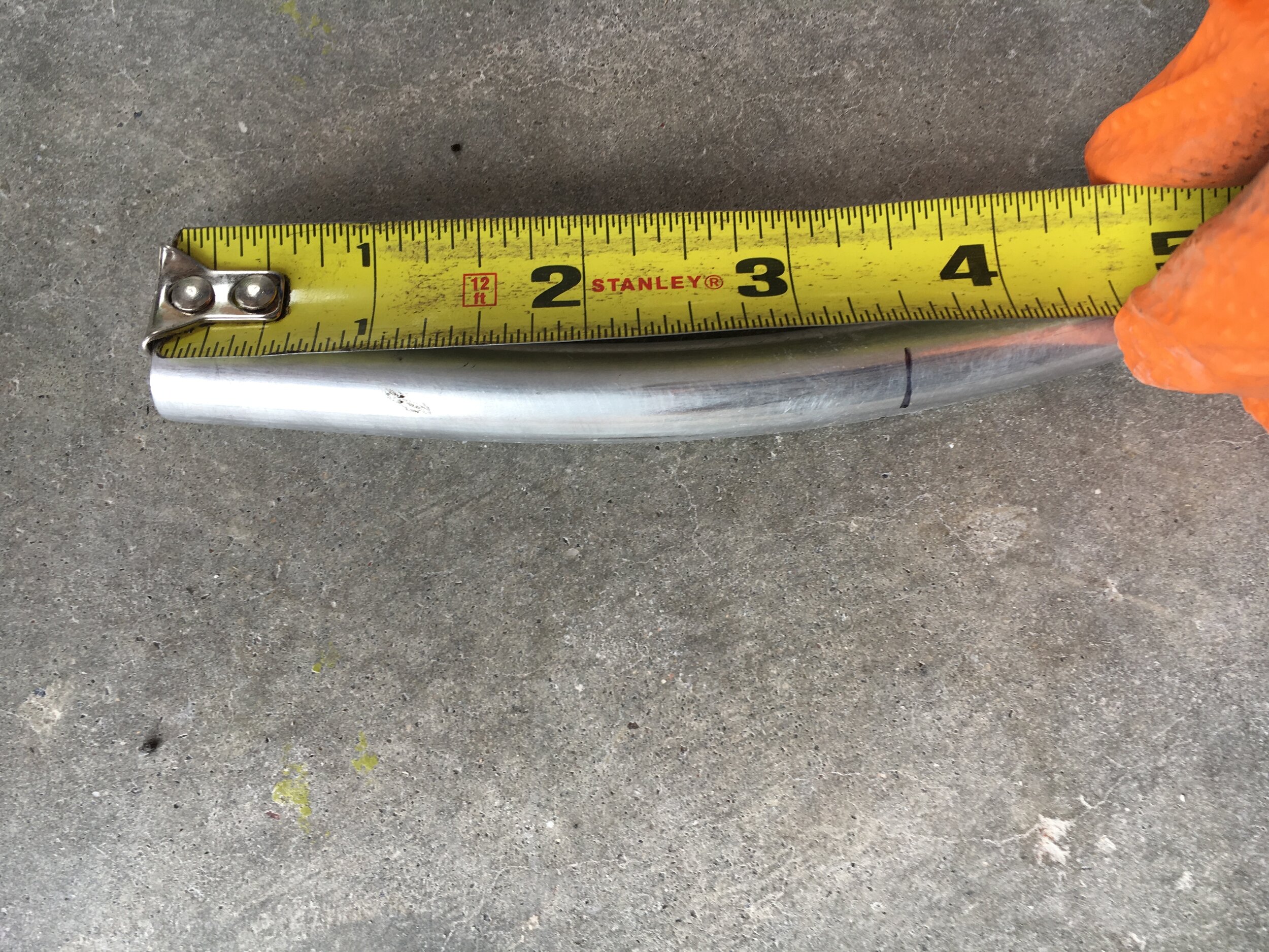
You must drill three holes: one for the 5/16" stainless steel high-pressure delivery line that heads from the pump to the engine bay; another for the short piece of 5/16” stainless line harvested from the 5/16” coil to connect the low-pressure fuel pump to the swirl tank (or two of these with the Metro Turbo-spec pump and regulator); and a third for the 1/2” return line to the swirl tank—if you are running the Walbro EFI-spec pump and Aeromotive regulator.
The massive 1/2” diameter return line is necessary to evacuate sufficient fuel to reduce the EFI-spec Walbro pump’s output to the 3 psi base pressure appropriate for the SU HIF44, but is probably not necessary if you elect to run the Metro Turbo-spec regulator and lower-volume pump. In the latter case, a 3/8” return line connected to a 5/6” hose barb fitting to run rubber fuel hose to the regulator’s 5/16” nipple should be adequate.
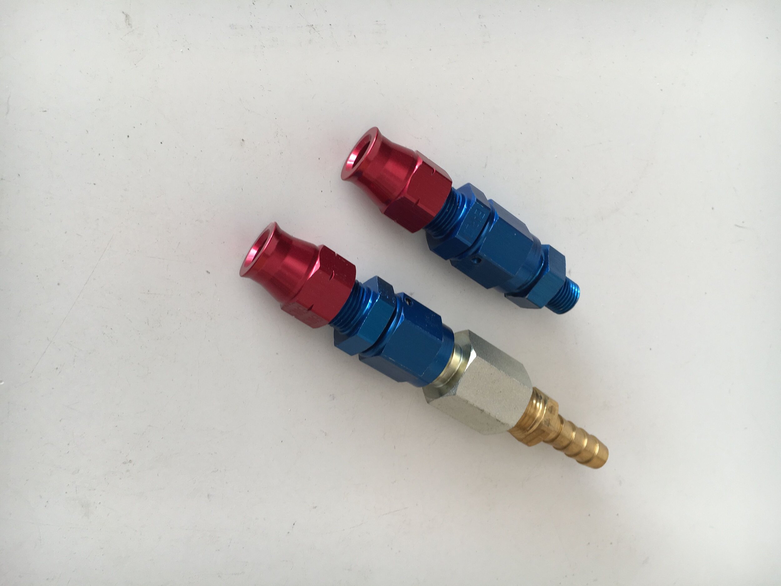
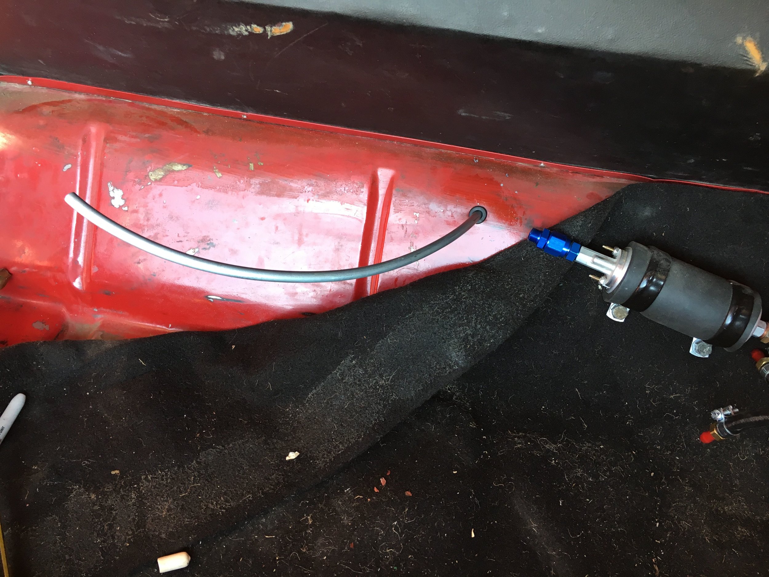
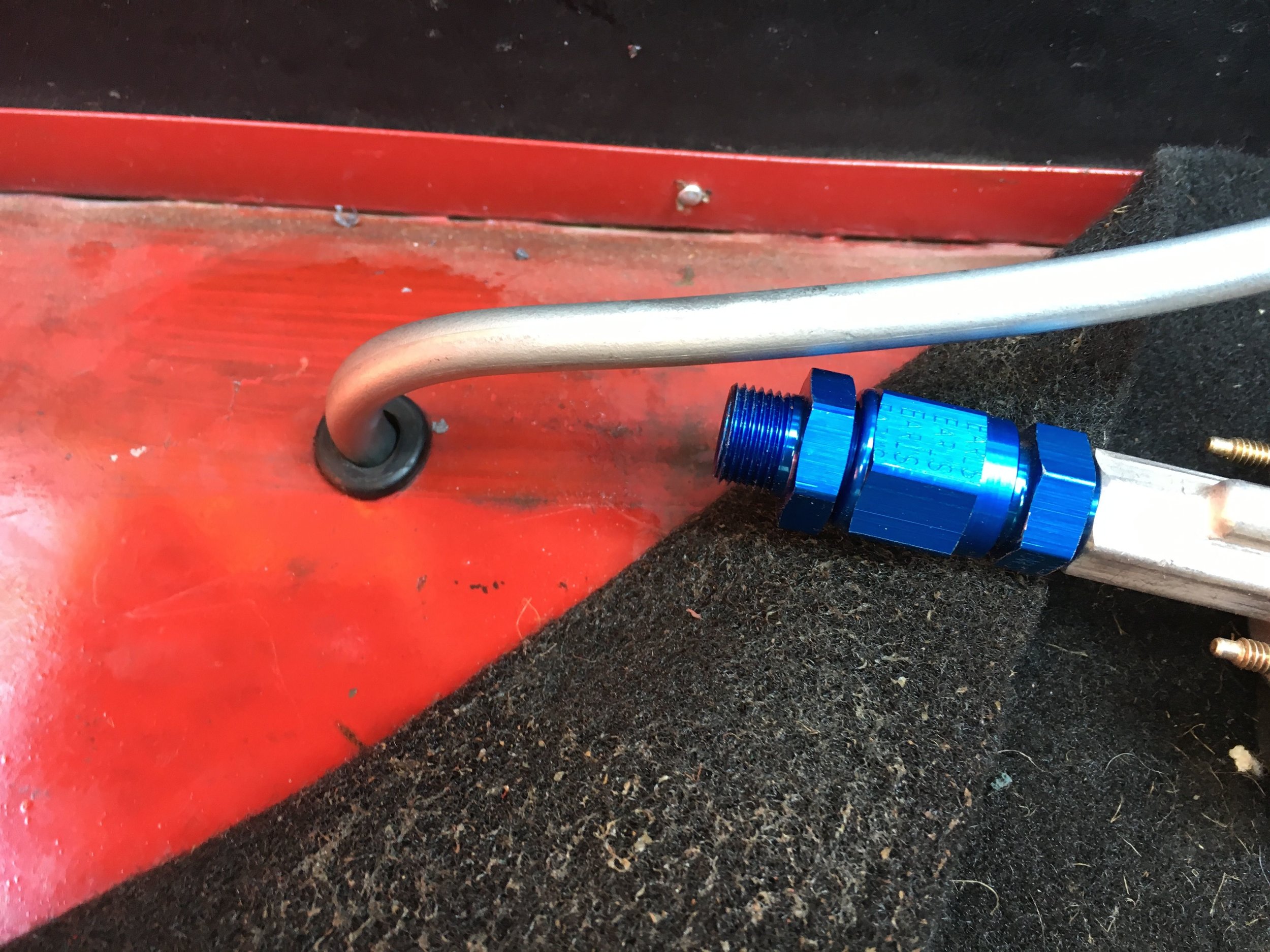
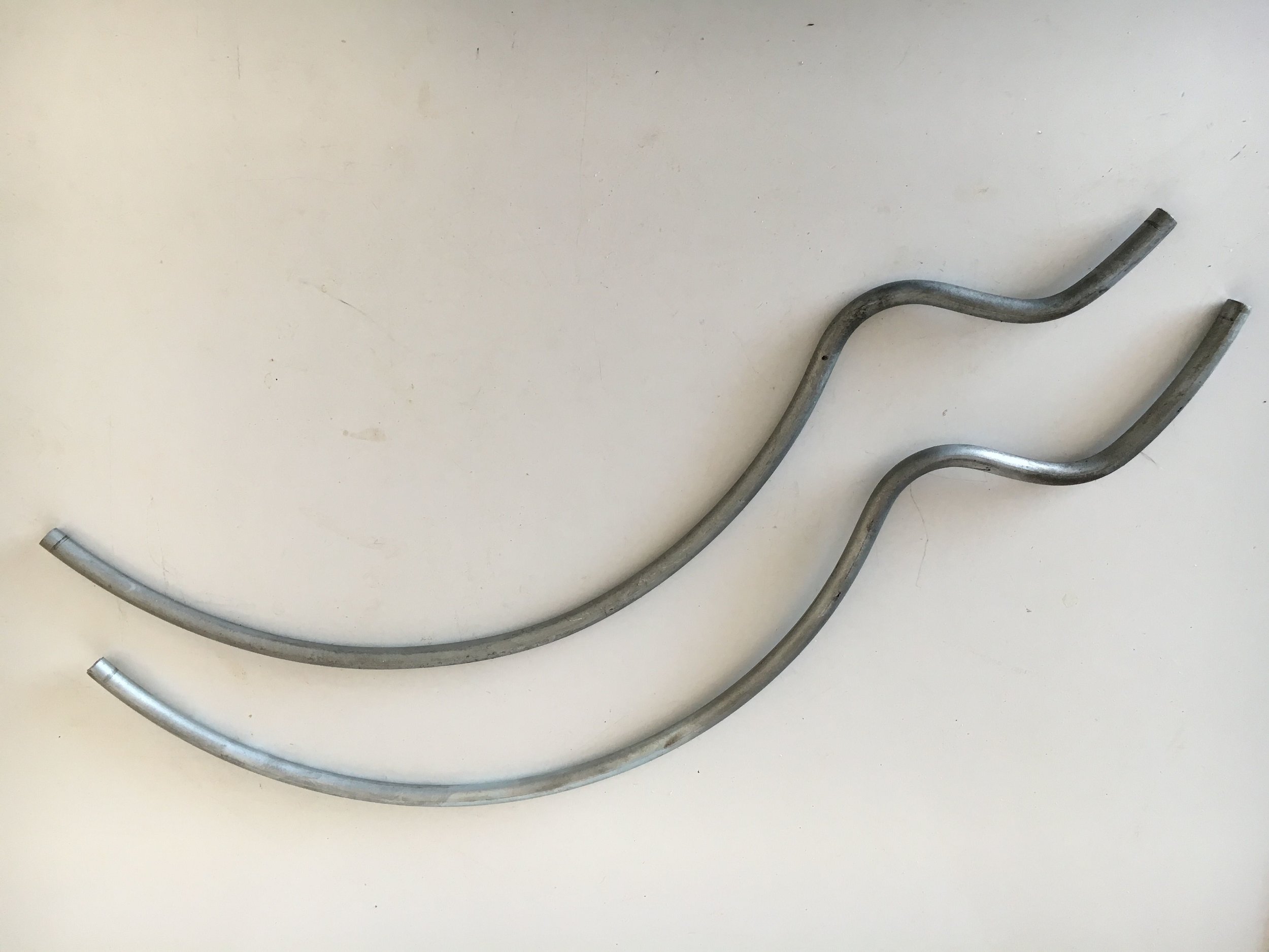
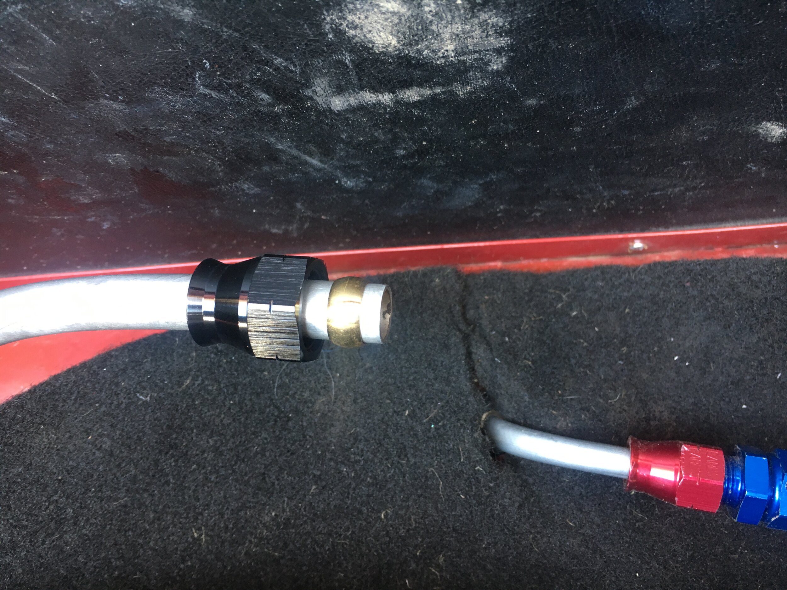
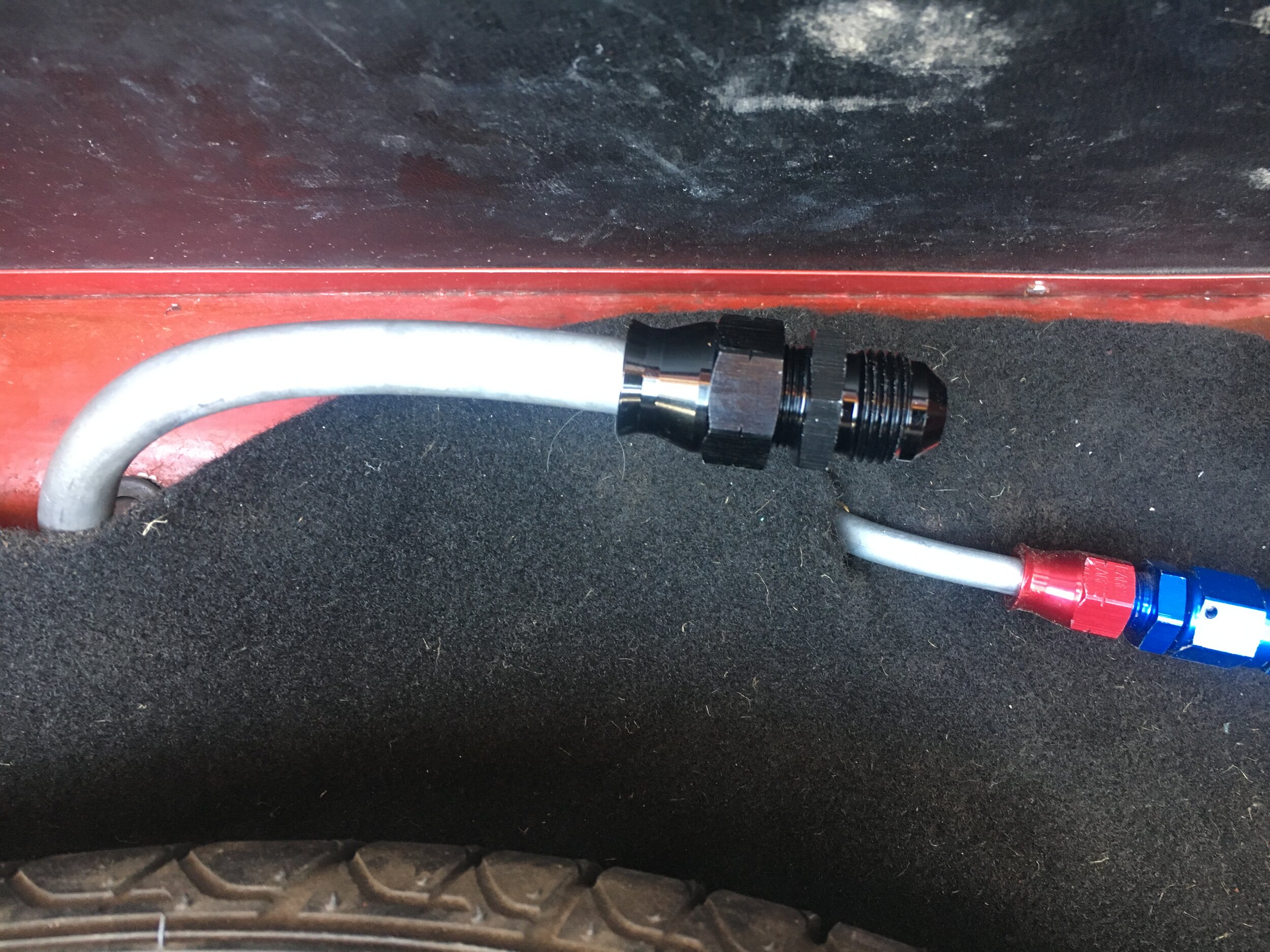
STEP 3 - Form the 5/16" stainless steel delivery line
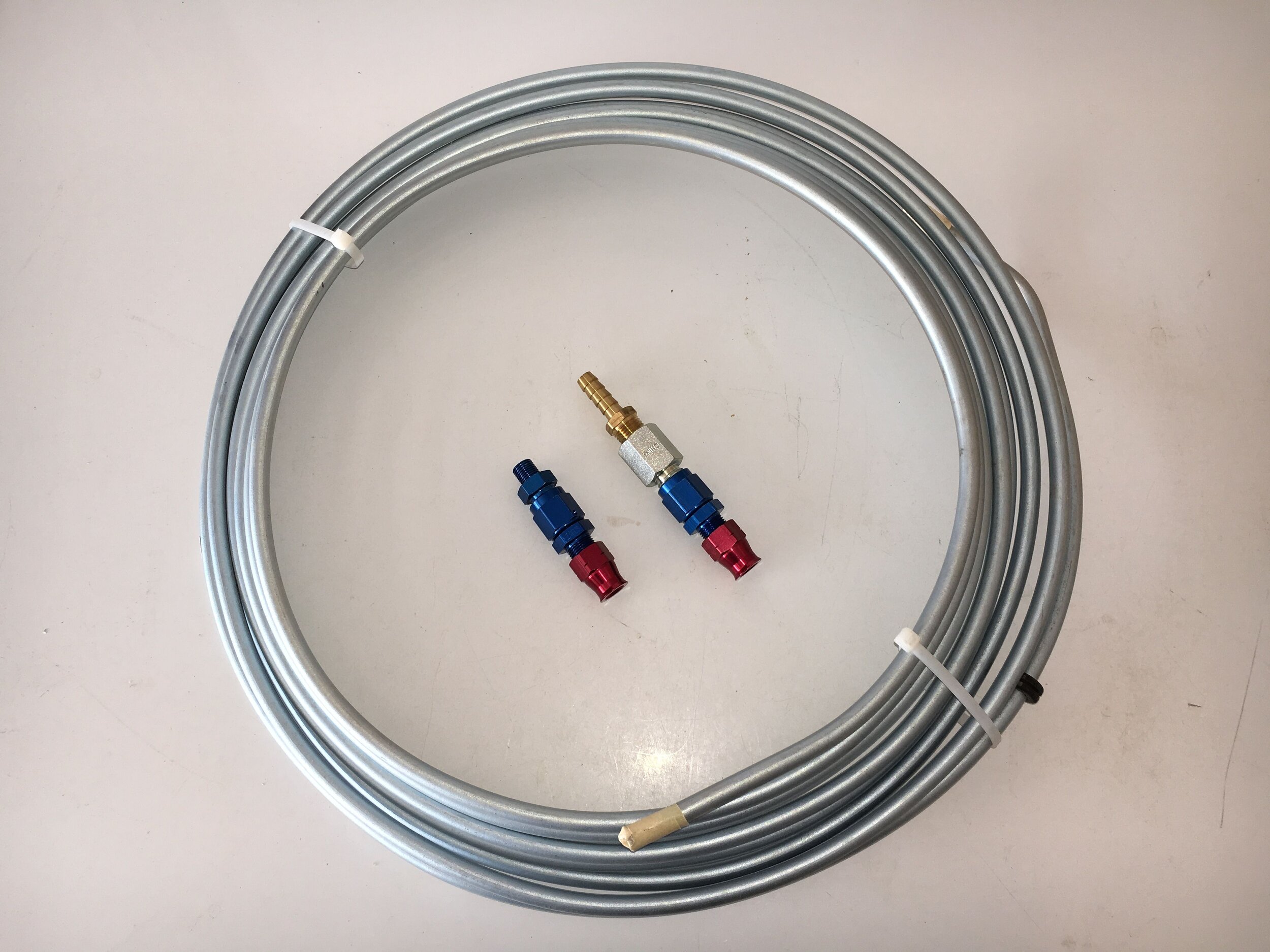
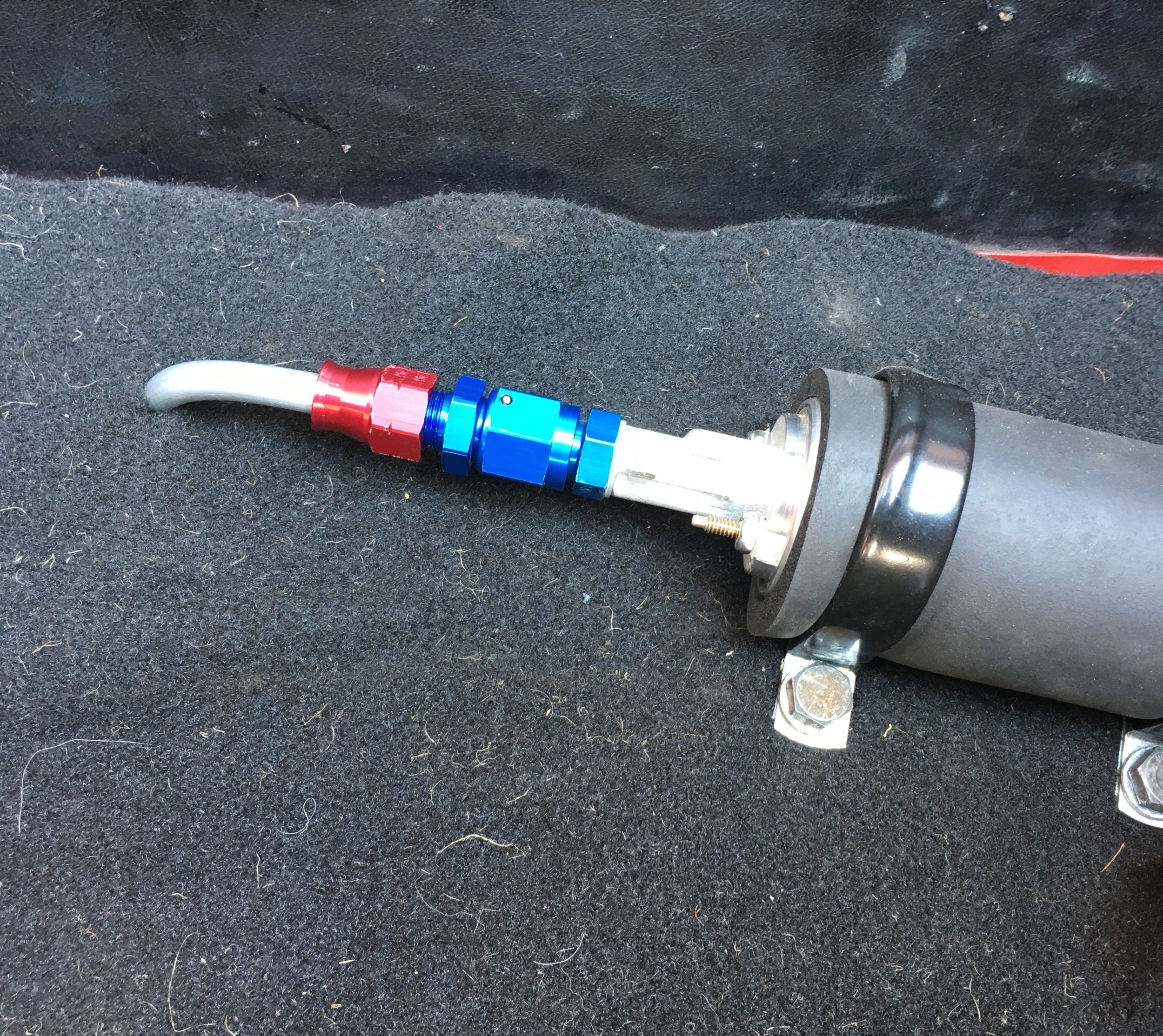
Here the 5/16” steel line, aluminum and steel AN fittings, and brass NPT to 5/15” hose barb adapter we used for the high-pressure delivery line:
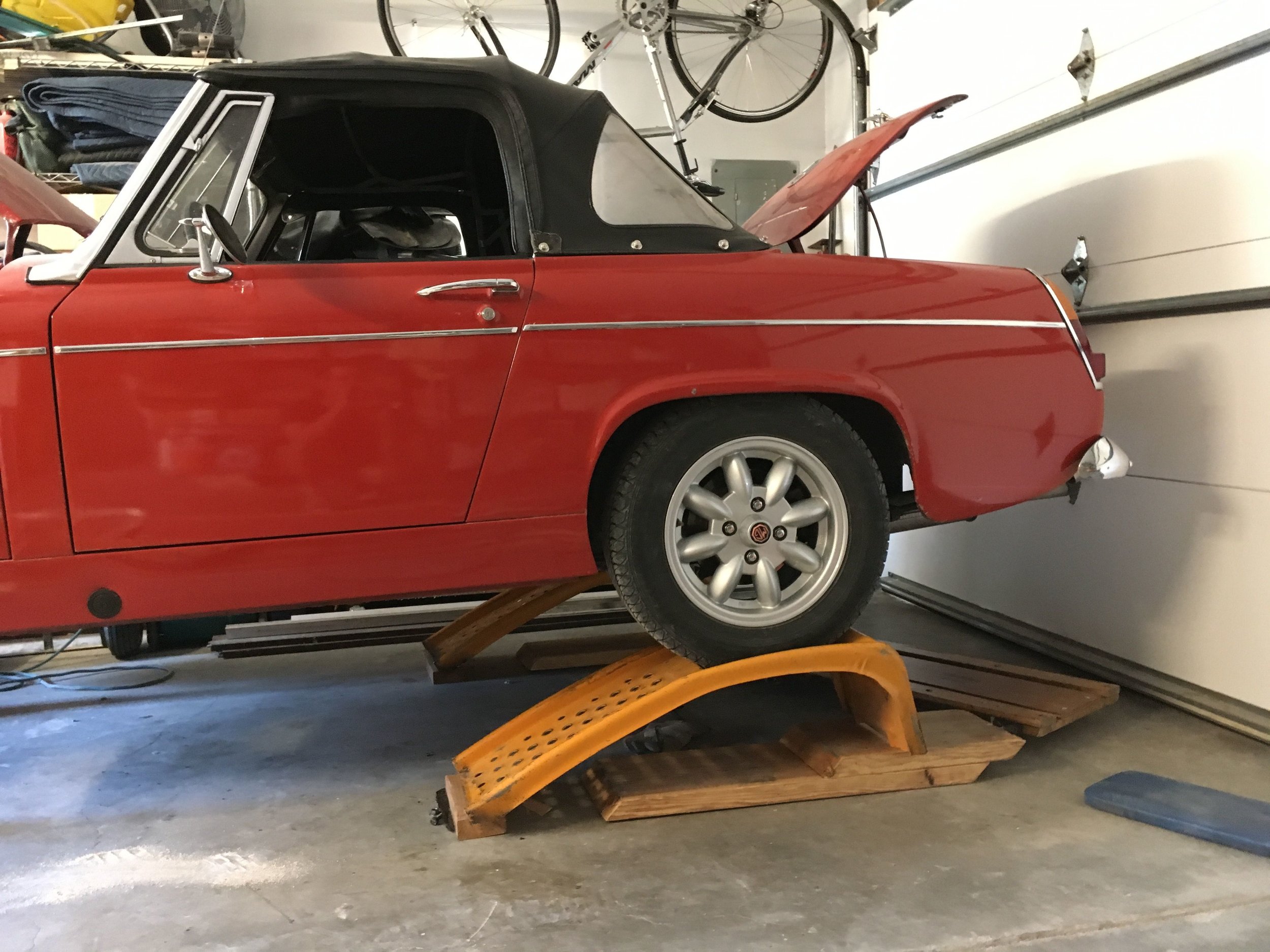
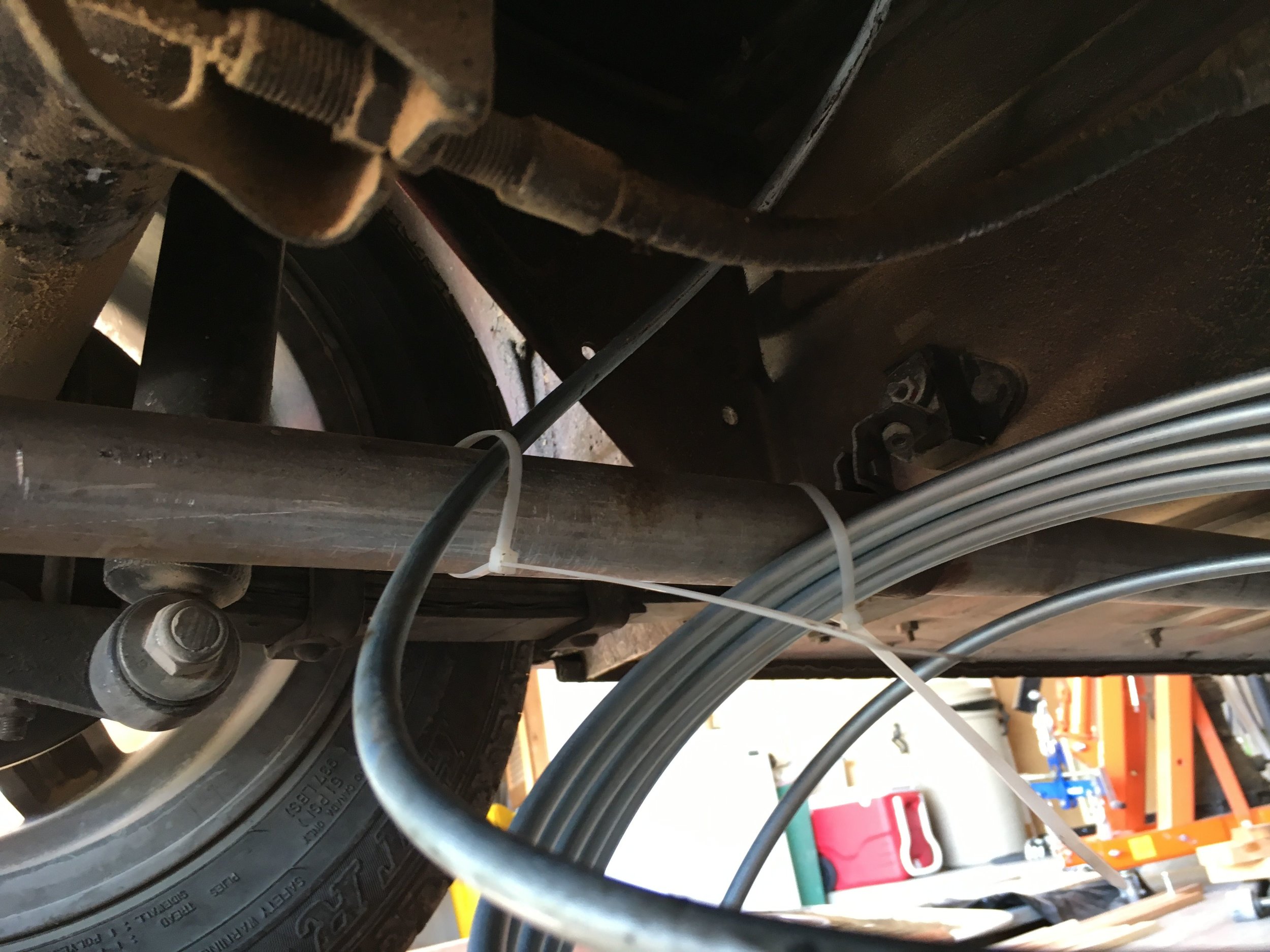
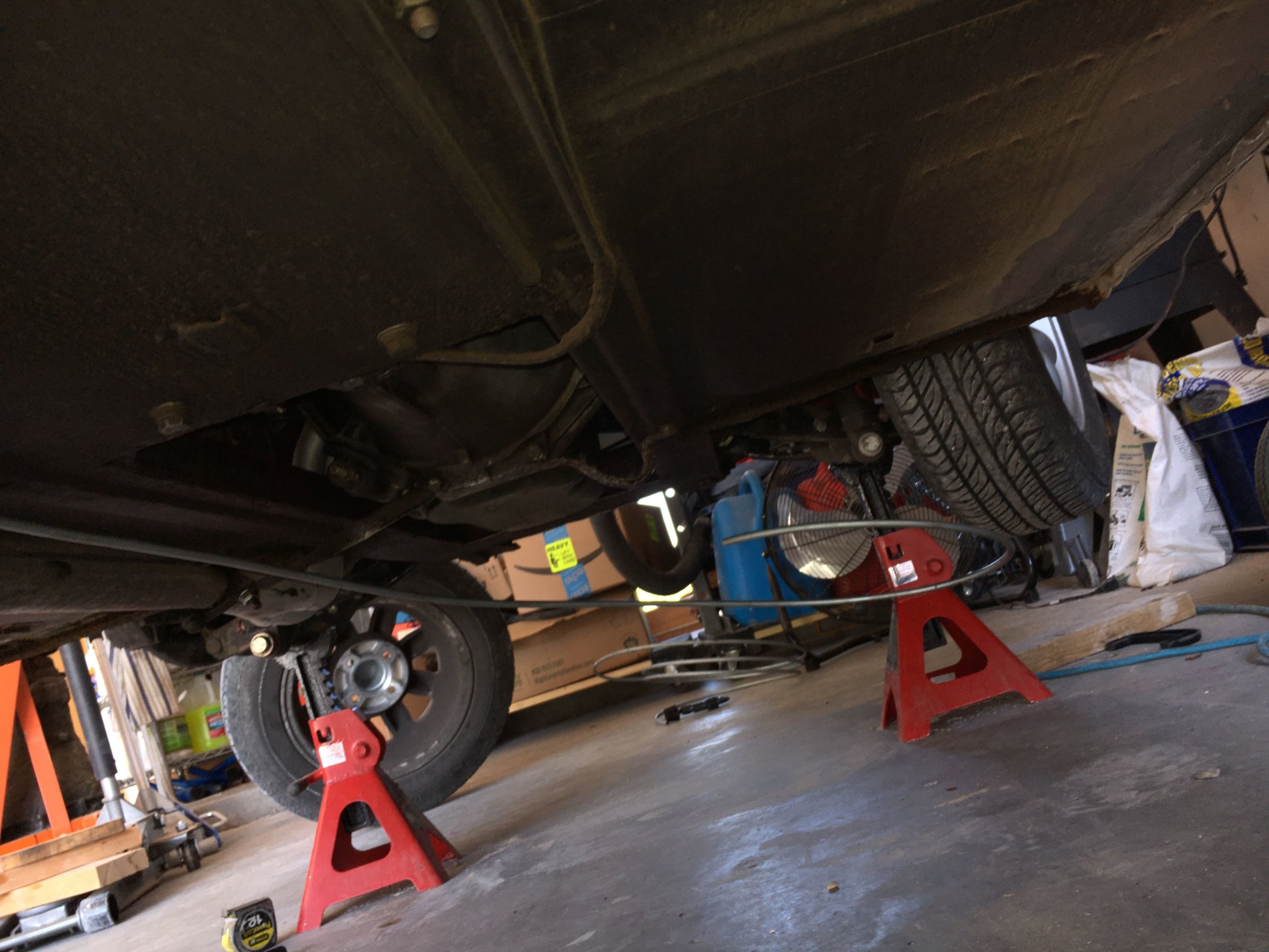
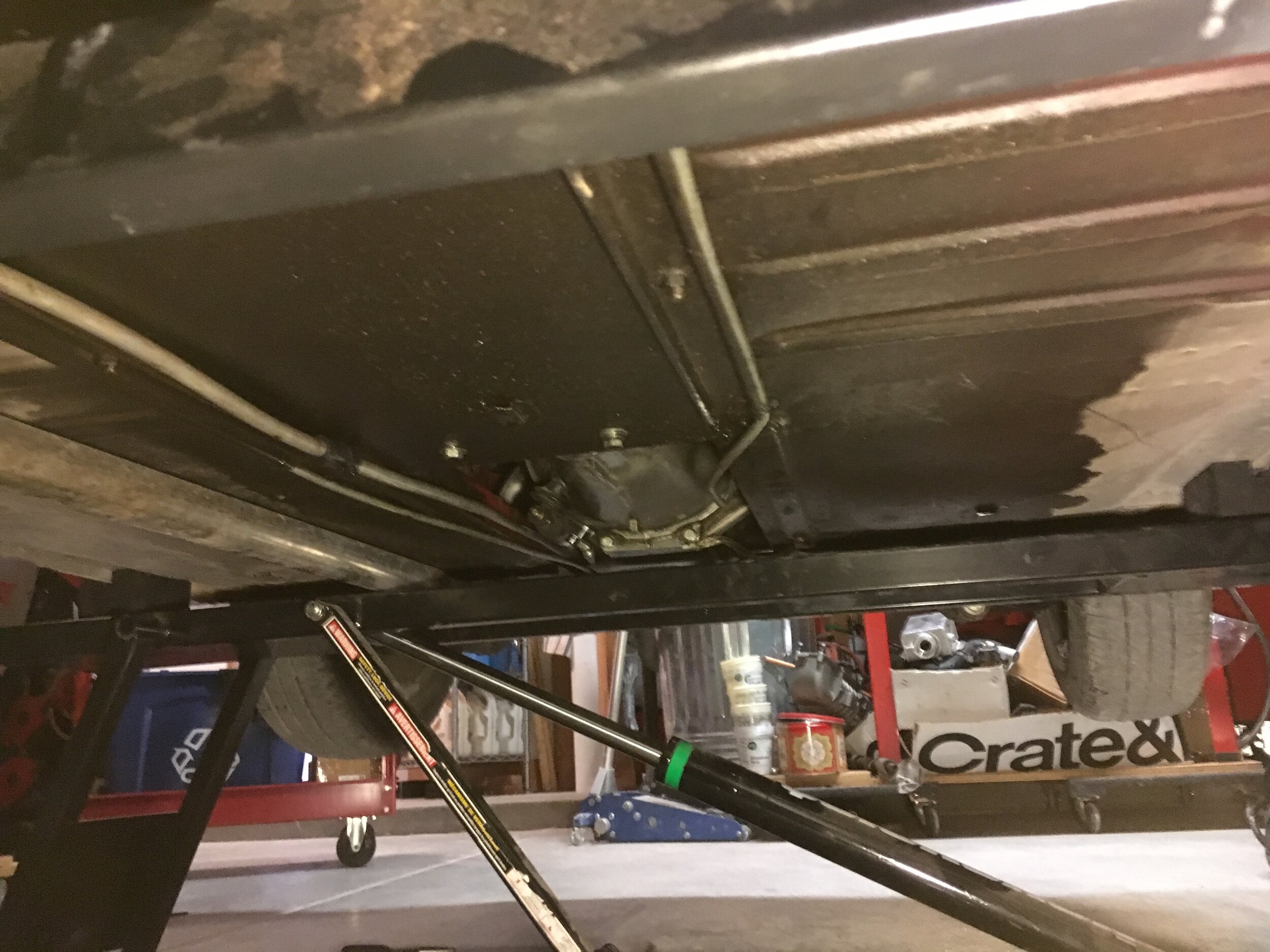
Forming and installing this and the return line may be the most physically demanding task in this conversion. The car must be raised high enough to allow for a creeper and elbow room to bend steel line, which is comparatively stiff.
The picture to the right below is NOT the way to go; our preferred method for DIYers is at left--jack stands up front, rear suspension on ramps at rear (on wooden boosters for more clearance). In the alternative, you could put jack stands under the axle tube, but that leaves less room for scooting around on a creeper:

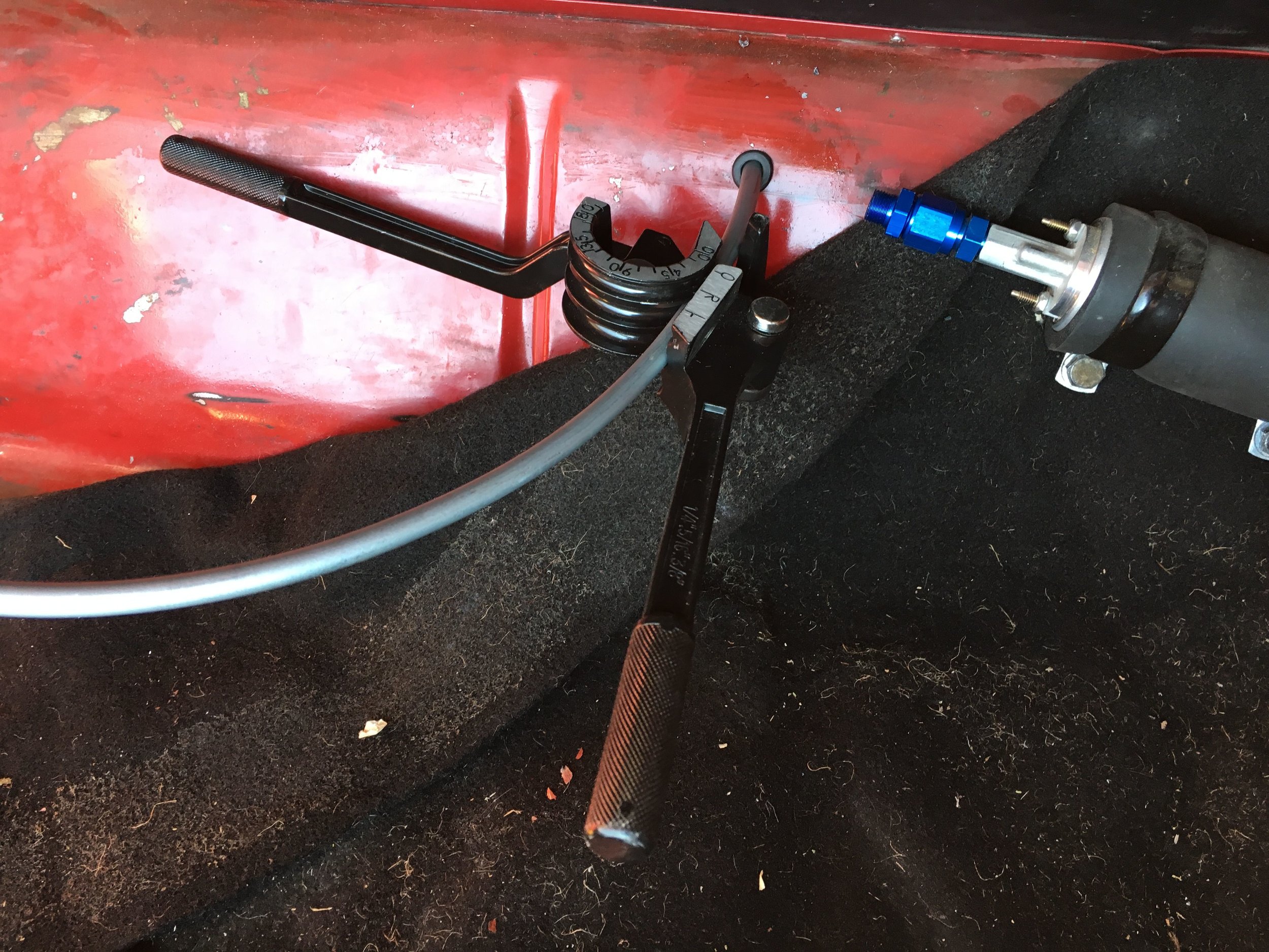
Now comes the tricky part, as shown in the following slide show.
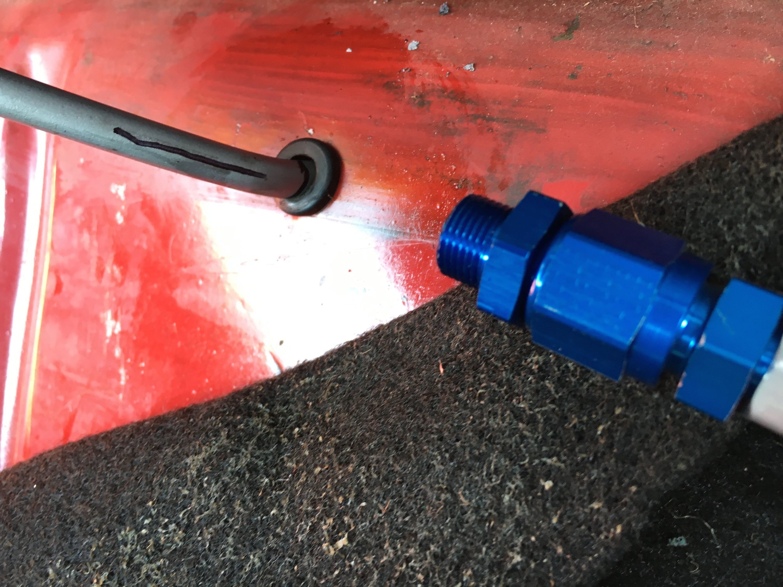
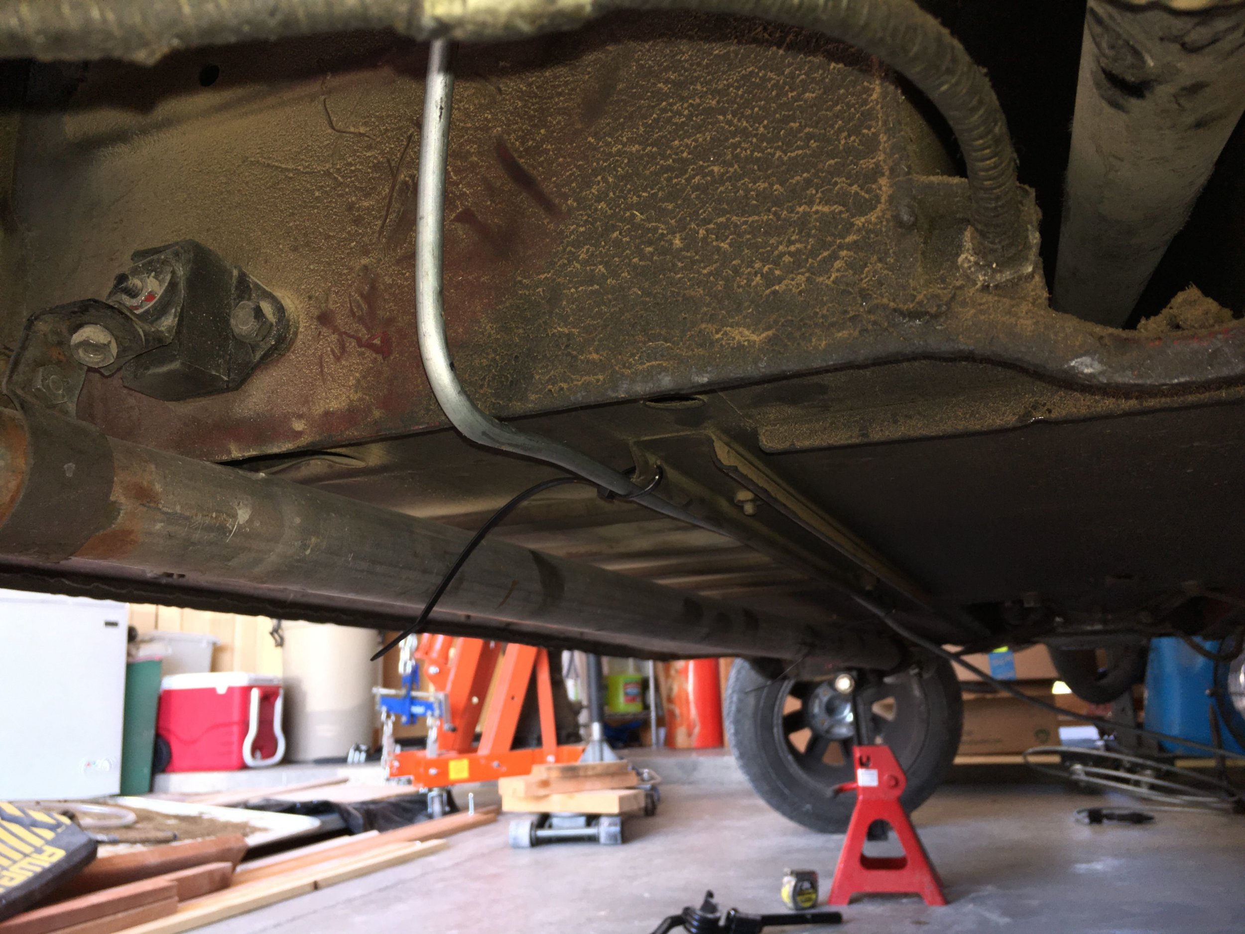
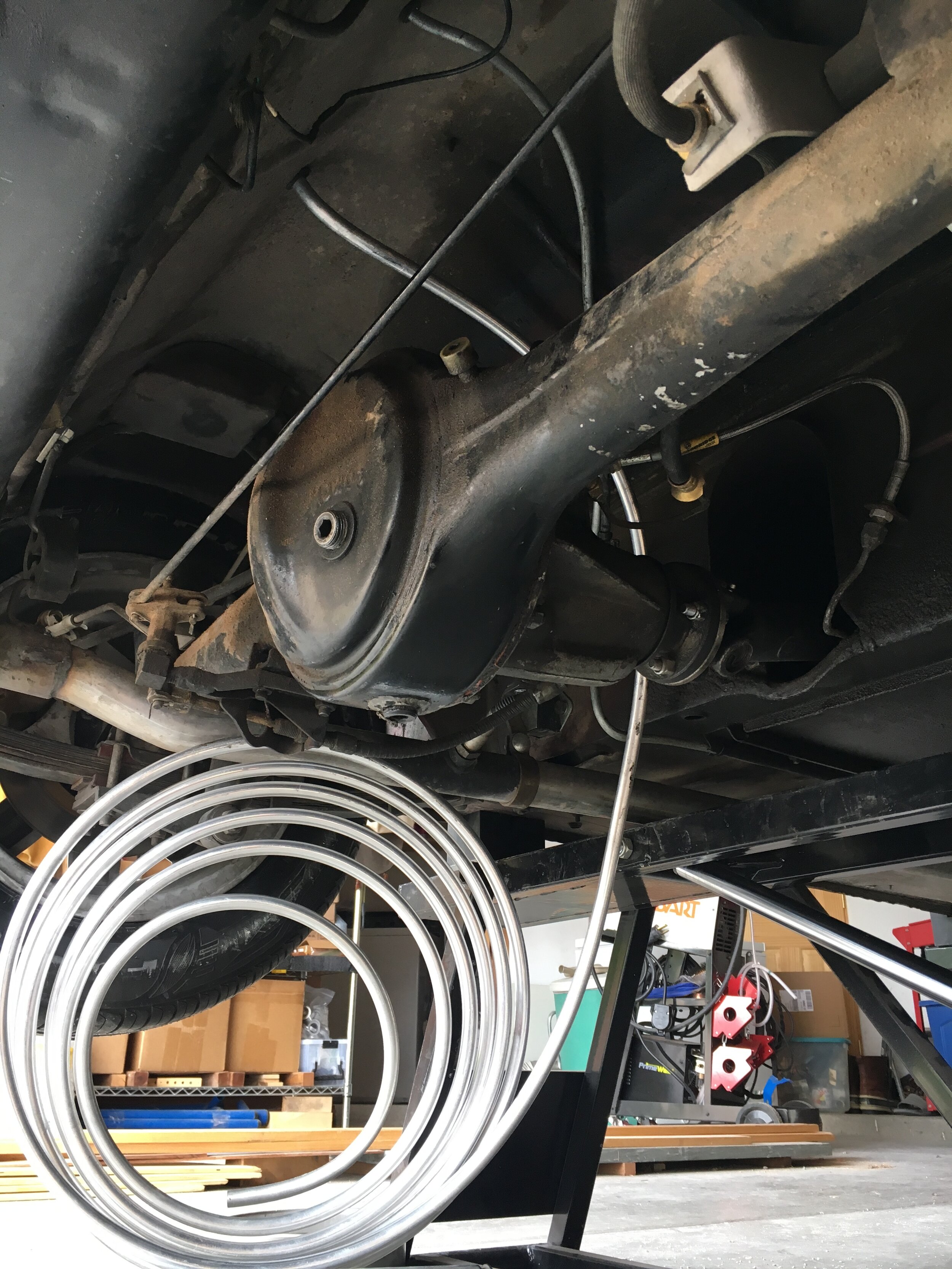
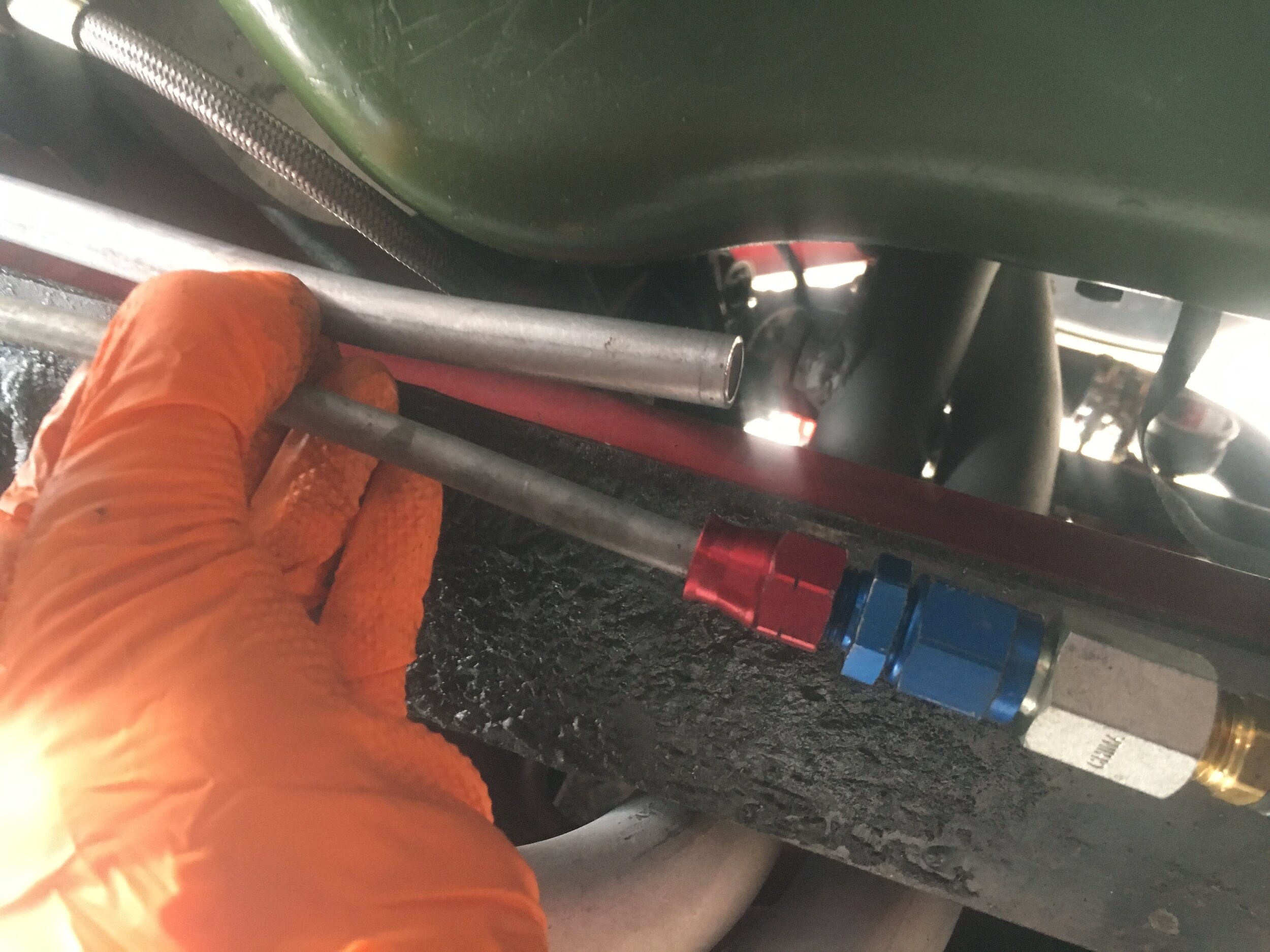
Working from beneath the boot, uncoil the stainless line slightly at one end by hand, so that you have perhaps 10~12" with a little larger radius than the natural coil. Then, relax the coil on the last round and work the spiral around the axle over the differential, so you can insert the end through the grommet into the boot:
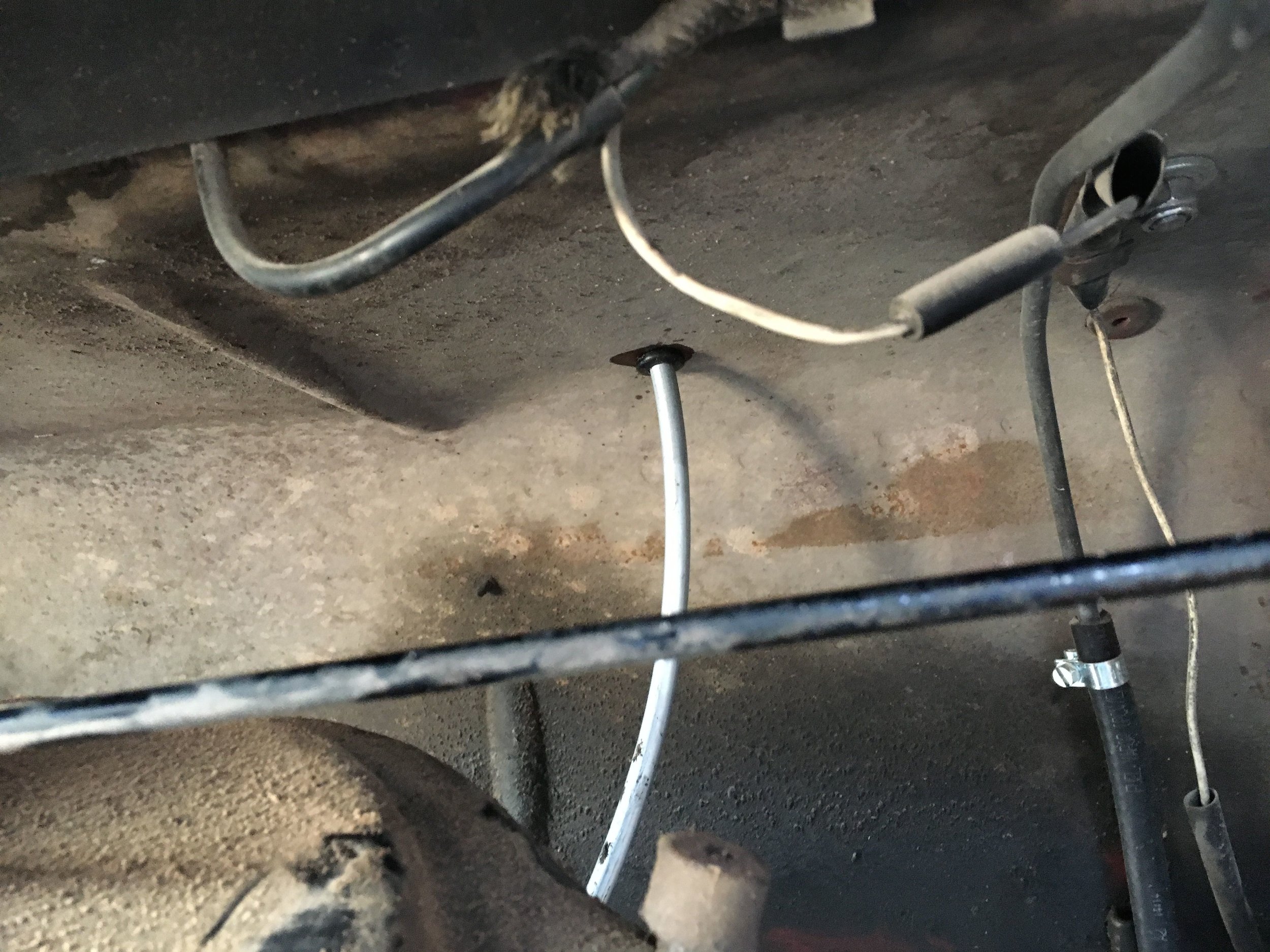
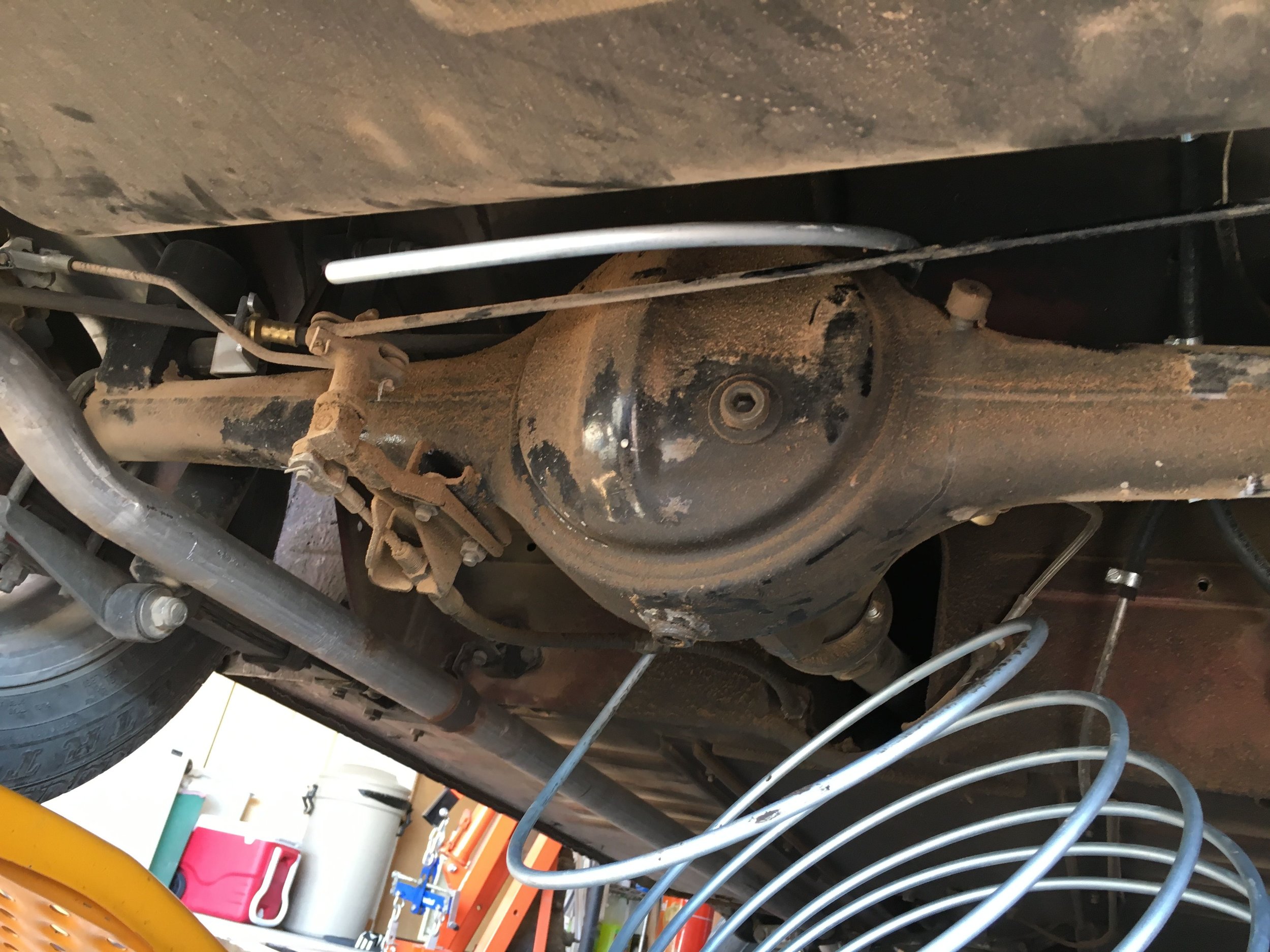
Next, bend the line away from the pump's outlet roughly 90 degrees or so:
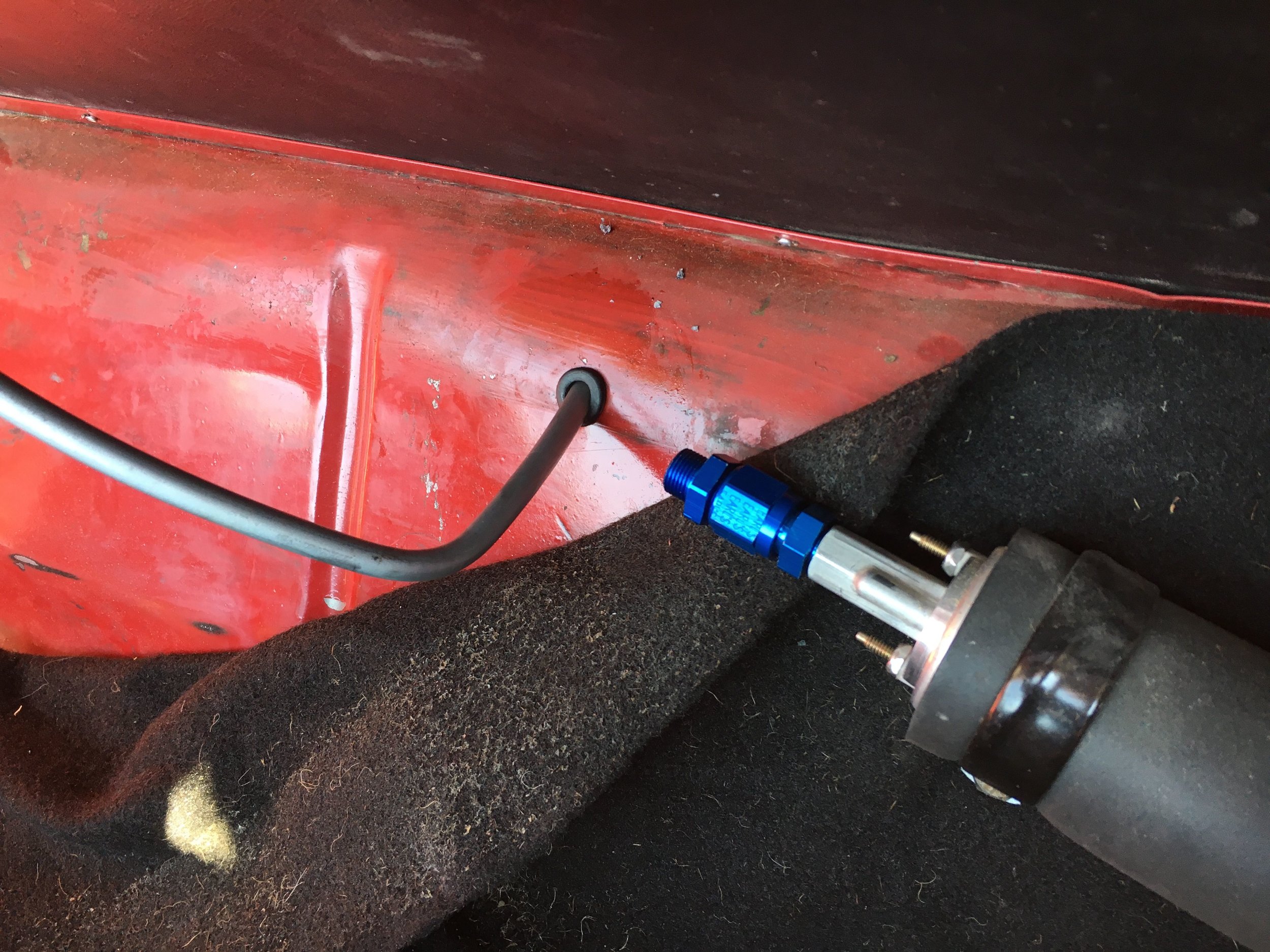
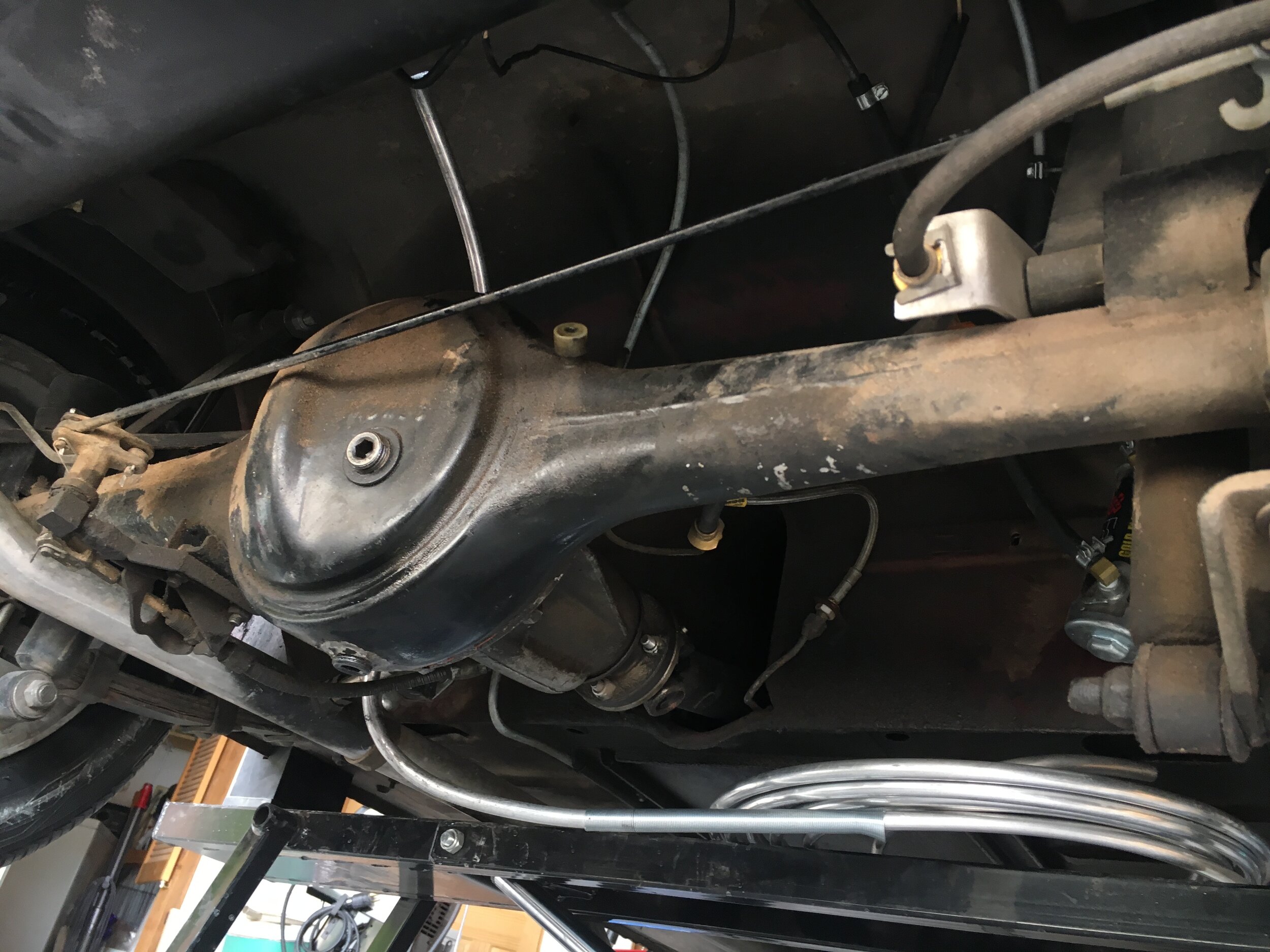
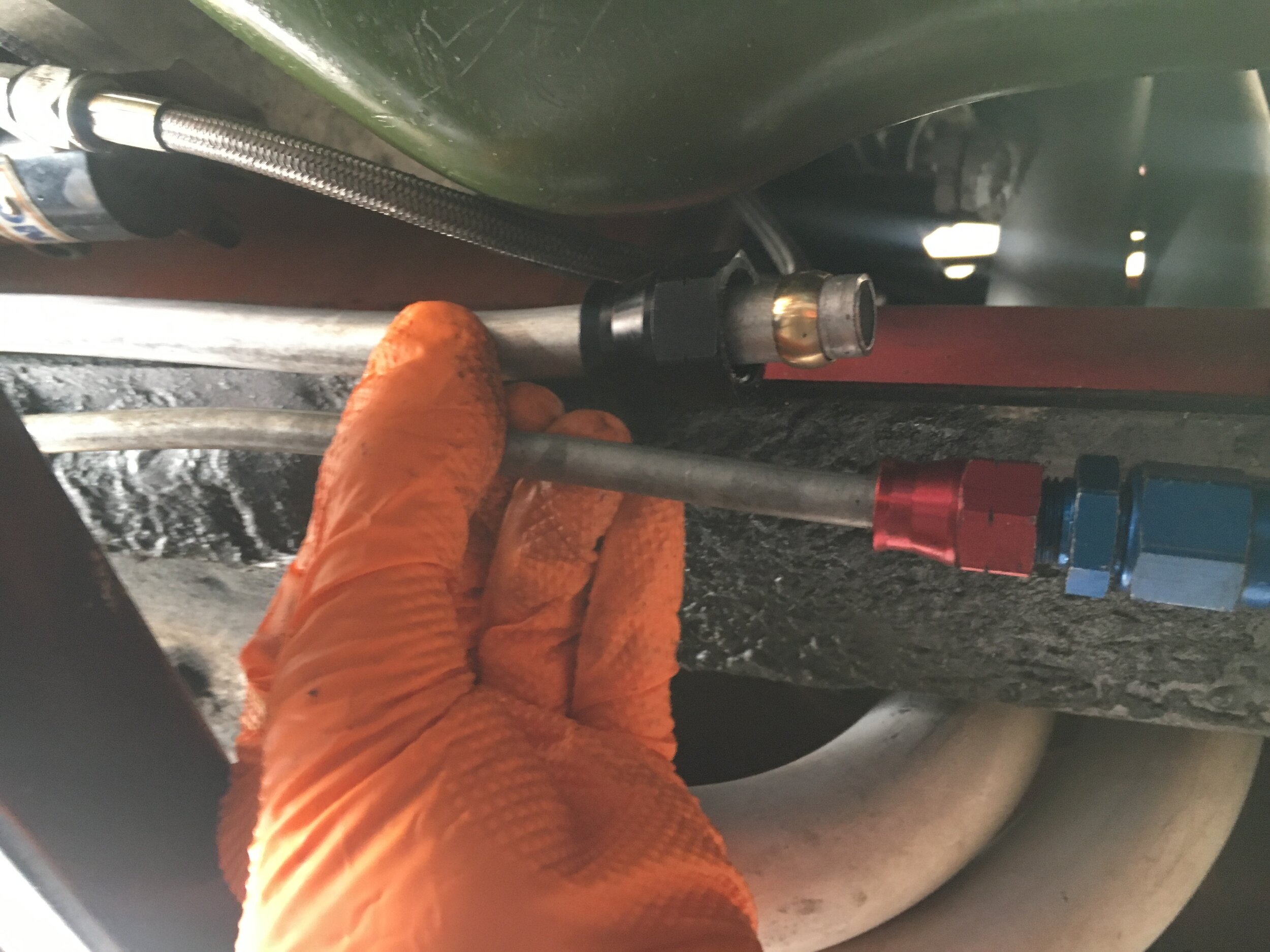
Now, back under the car and pull the bend you've made a hair through the grommet. Then, relax the coil a bit and push it up into the axle arch, and when reasonably close, zip tie it to the axle or exhaust pipe to hold the bend roughly parallel to the arch:
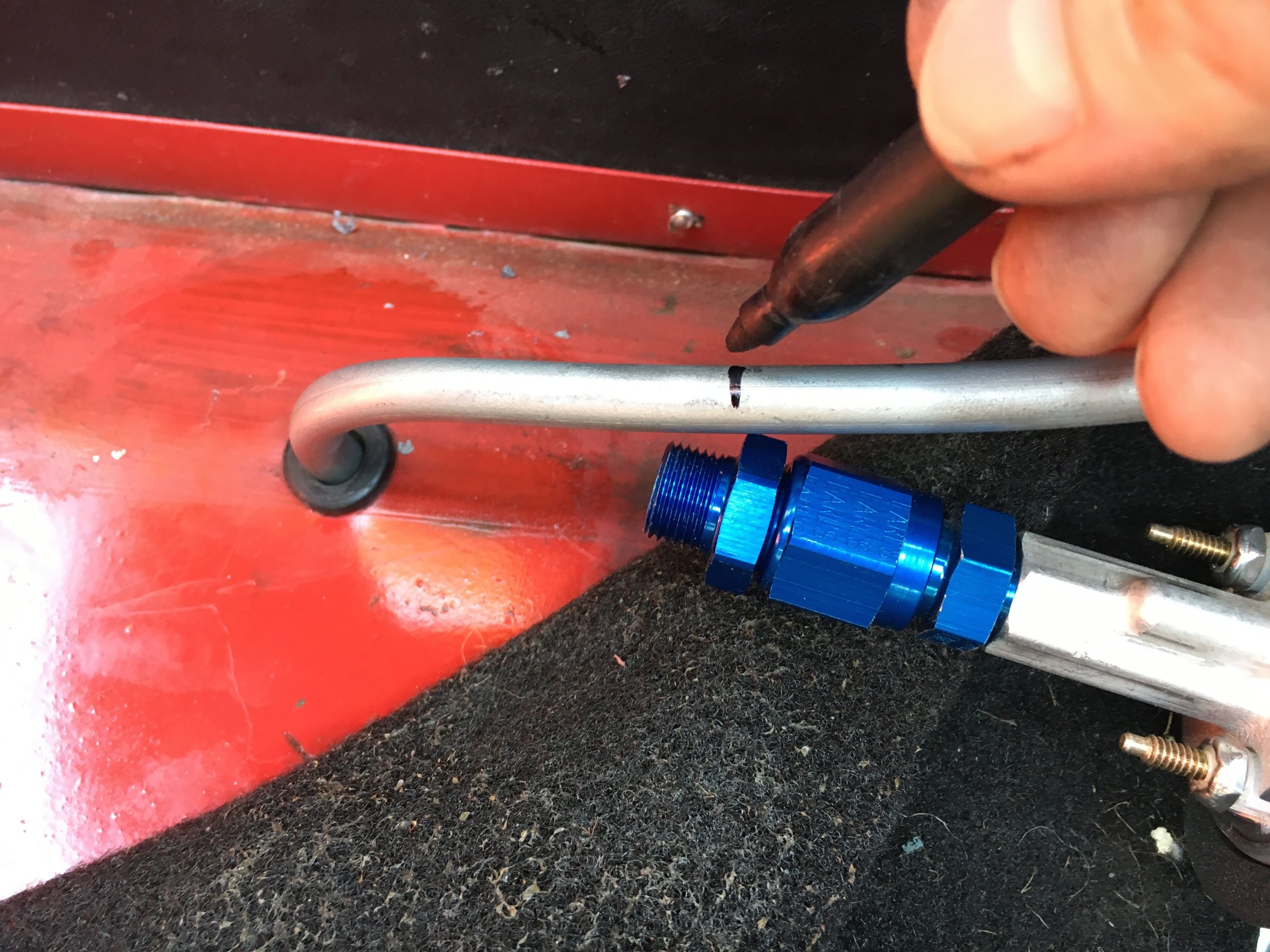
Now, back to the boot, where you will mark the line in two ways: first, to show where it comes through the grommet; second, with a longitudinal line showing what will become the inside of the next curve:
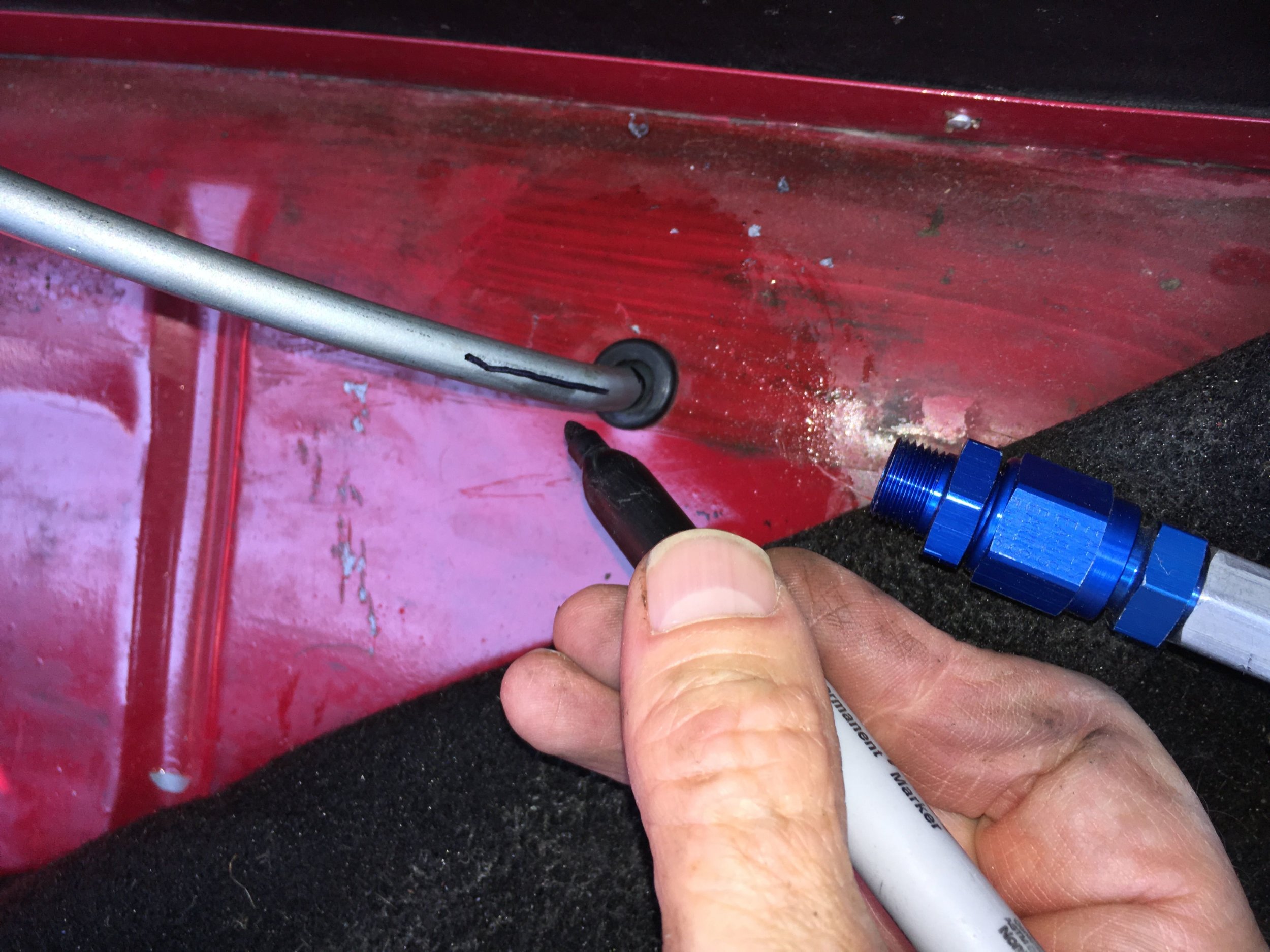
Next, pull the line back into the boot a little ways to make room for the tool, and using the index mark you've made, bend toward the pump. Then push the line back through to bring the run close to the pump outlet to judge the angle. The line must have a straight section just the right length to insert into the pump fitting and slip the female AN flange freely onto the line:
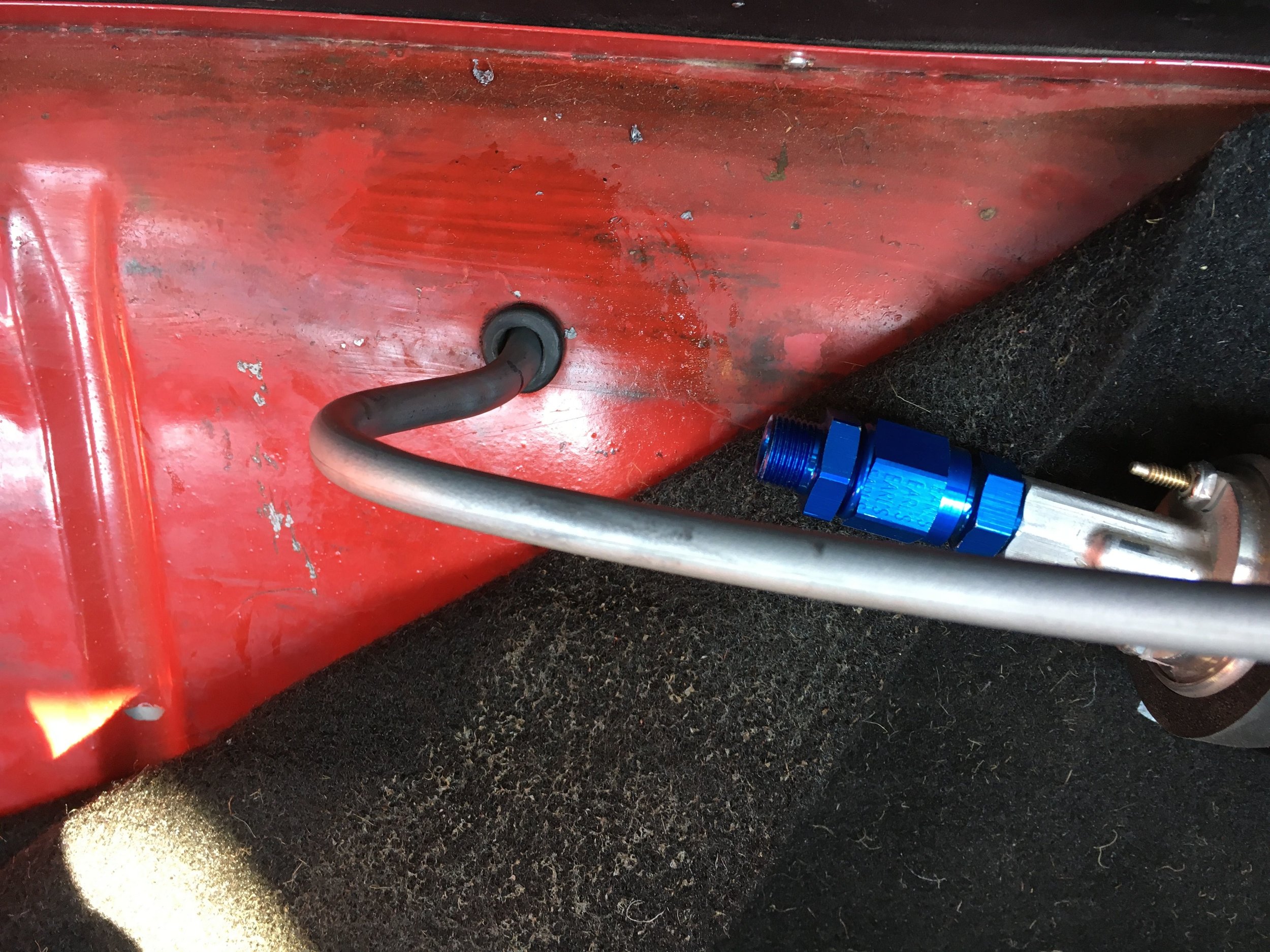
It is now time to mark and cut the line. When marking, make sure you know how far the line inserts into the pump outlet fitting (not much). A mini-tubing cutter helps here:
Finally, attach the fittings to the line and tighten everything down. It is much easier to do this if you unbolt the pump first, then reattach the clamps. However, do not forget that you must have a straight section for the AN sleeve and brass bead to slip on freely:
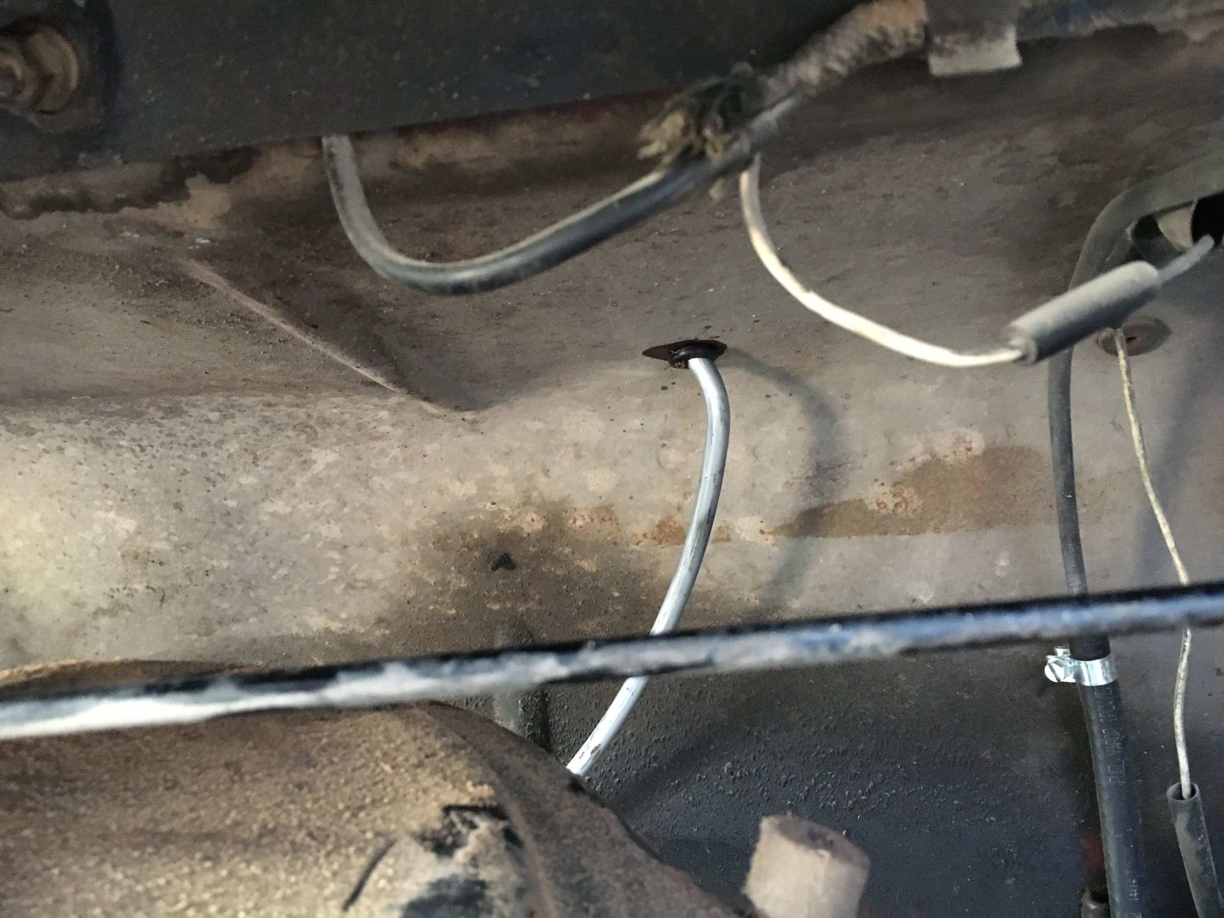
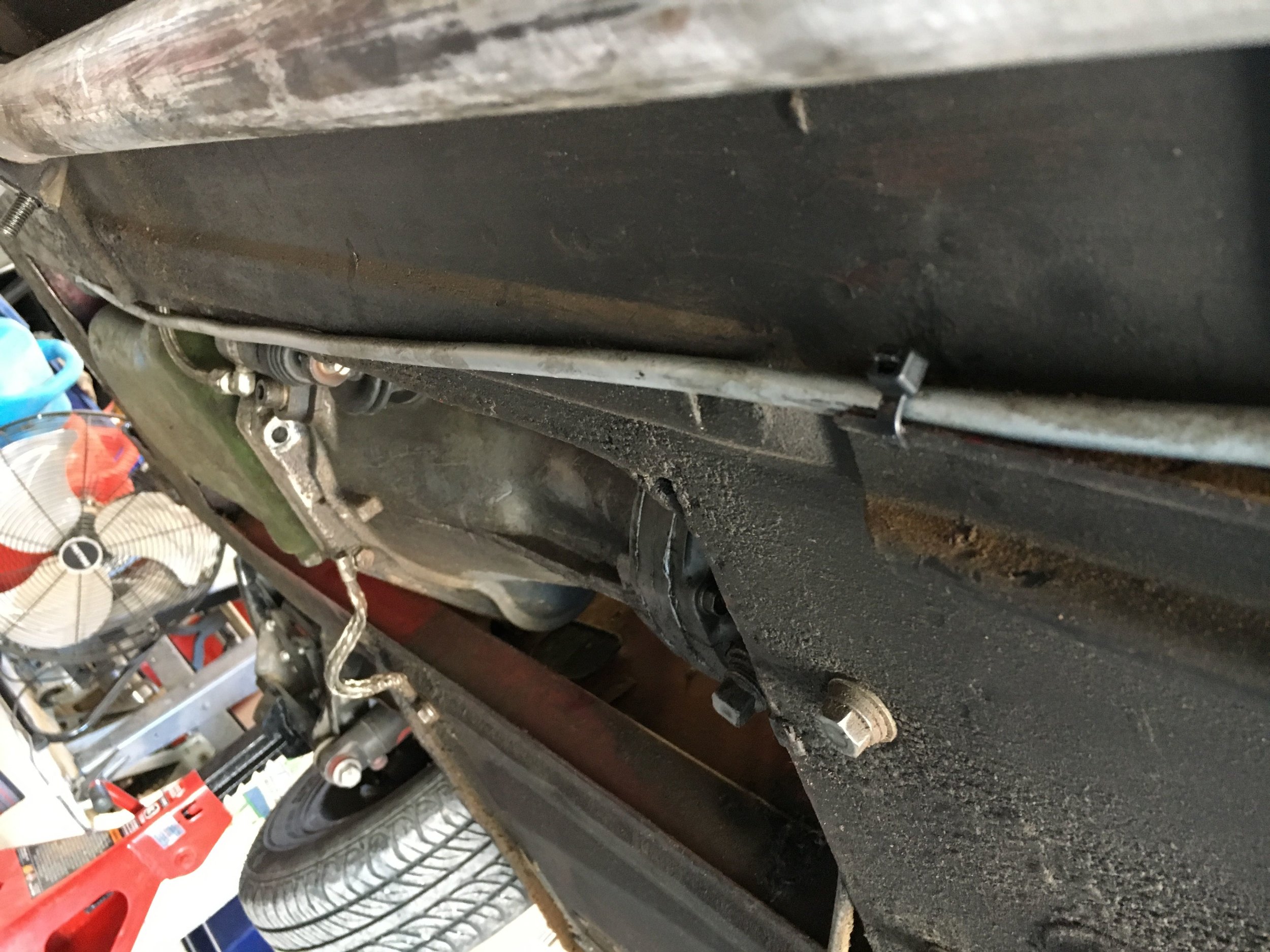
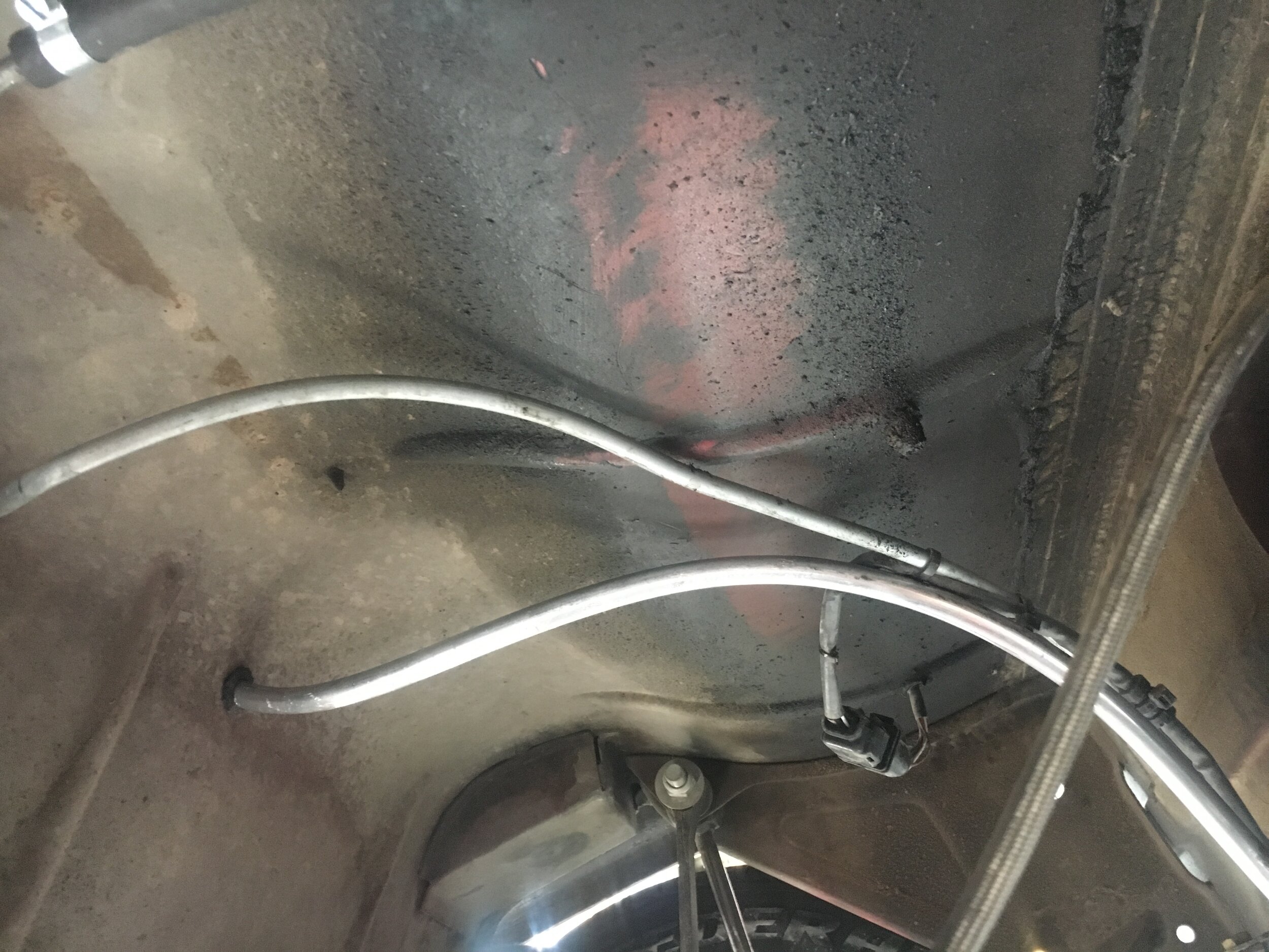
It's now time to go back under the car and finish forming the curve to match the axle arch, and then make the bend to send the line forward as shown in this series. You will notice that in the last picture, the unused portion of the coil has been cut off, leaving much more line than you will actually need. The line will terminate adjacent to the oil pan, toward the front of the engine.
STEP 4 - Attach AN fittings and connect delivery line to regulator
Simply attach the AN fitting to the forward end of the delivery line adjacent to the oil pan or another convenient spot, and then connect the 5/16” EFI-spec rubber fuel hose to the pressure regulator’s inlet.
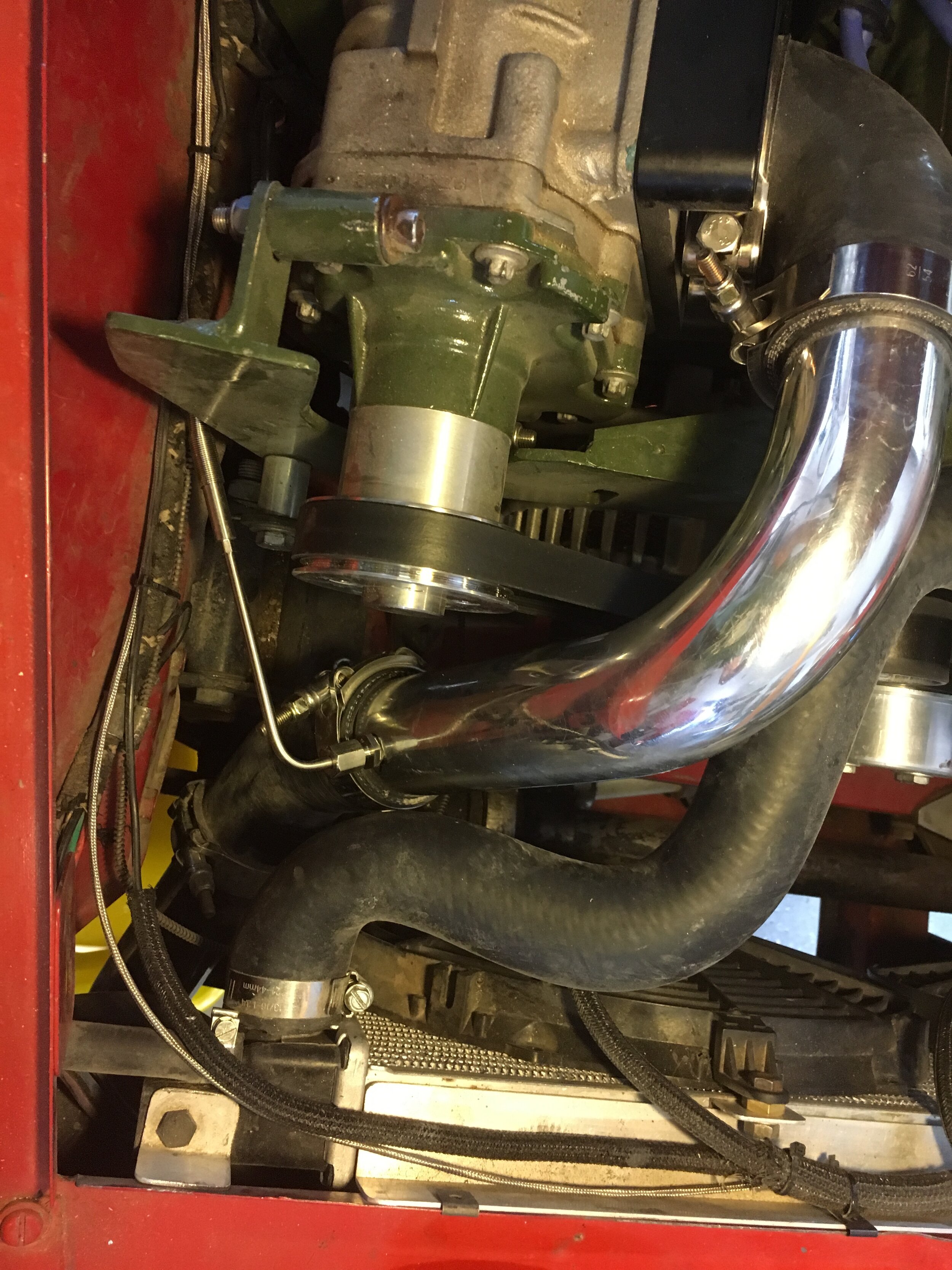
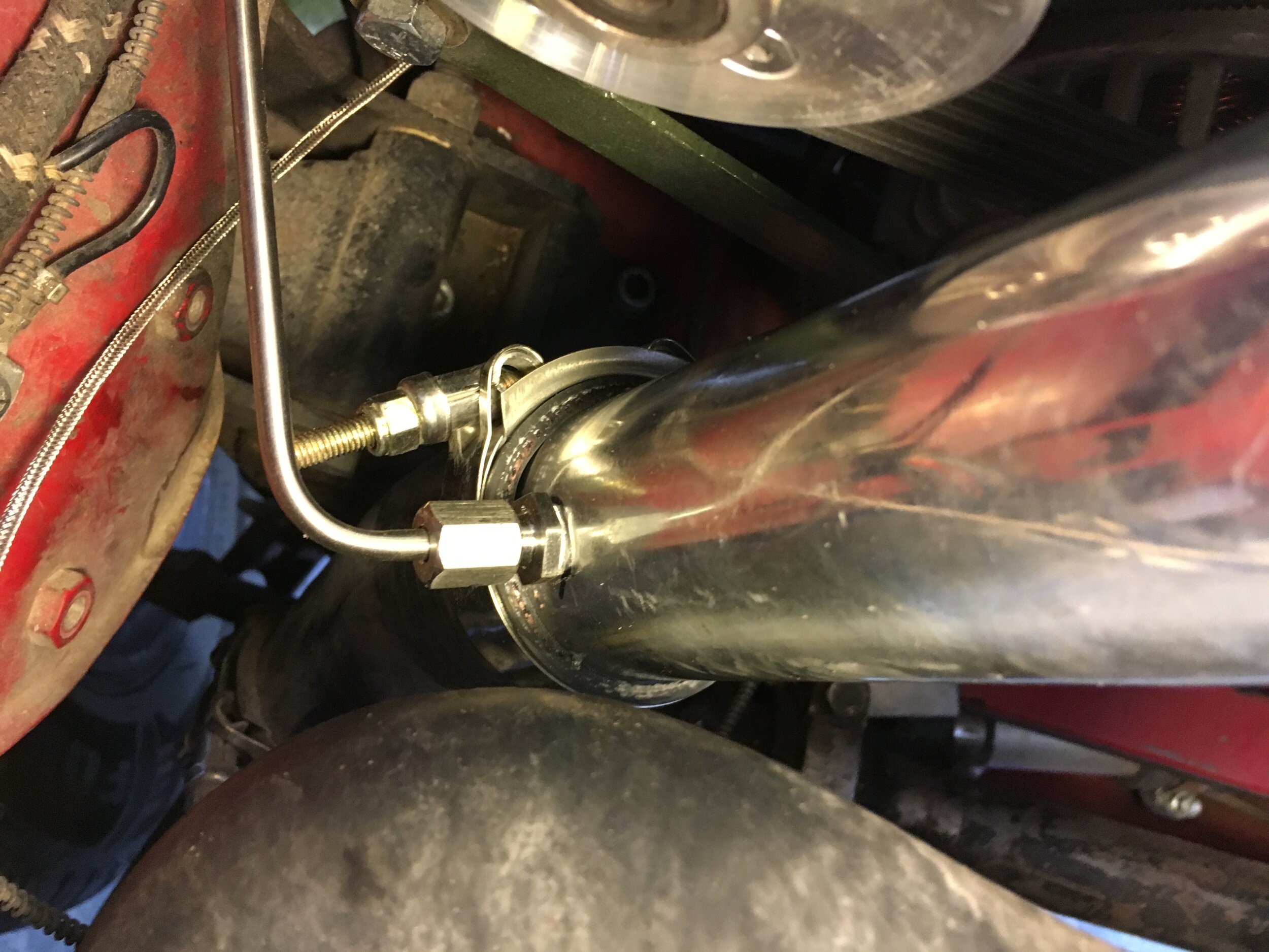
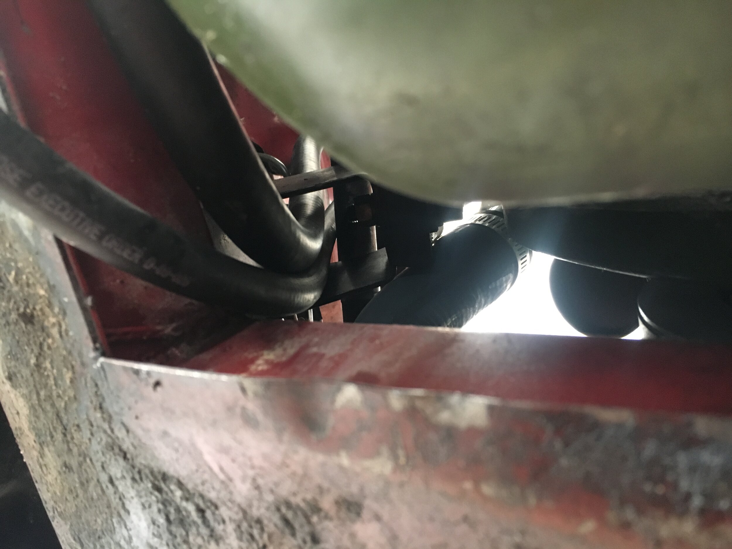
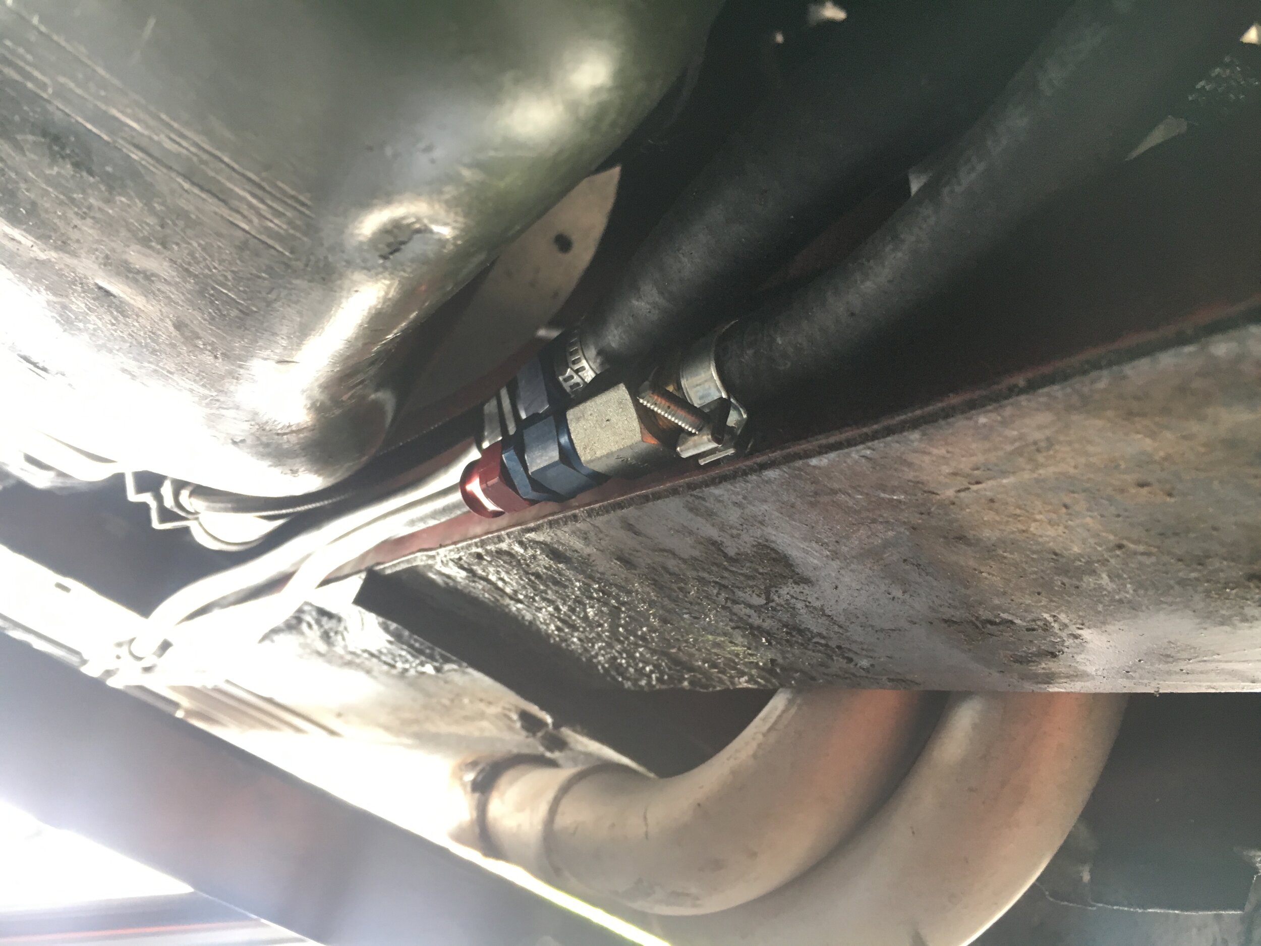
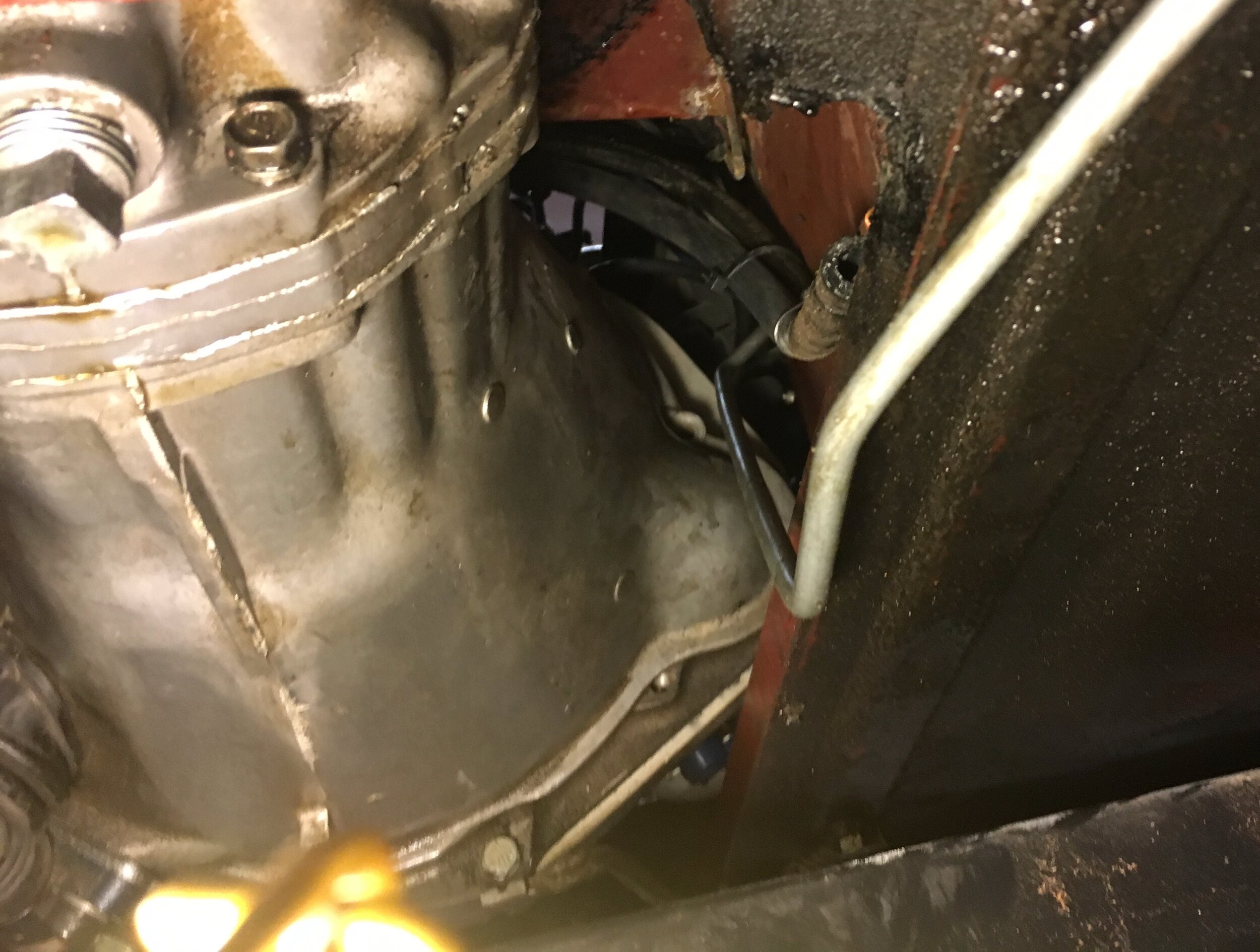
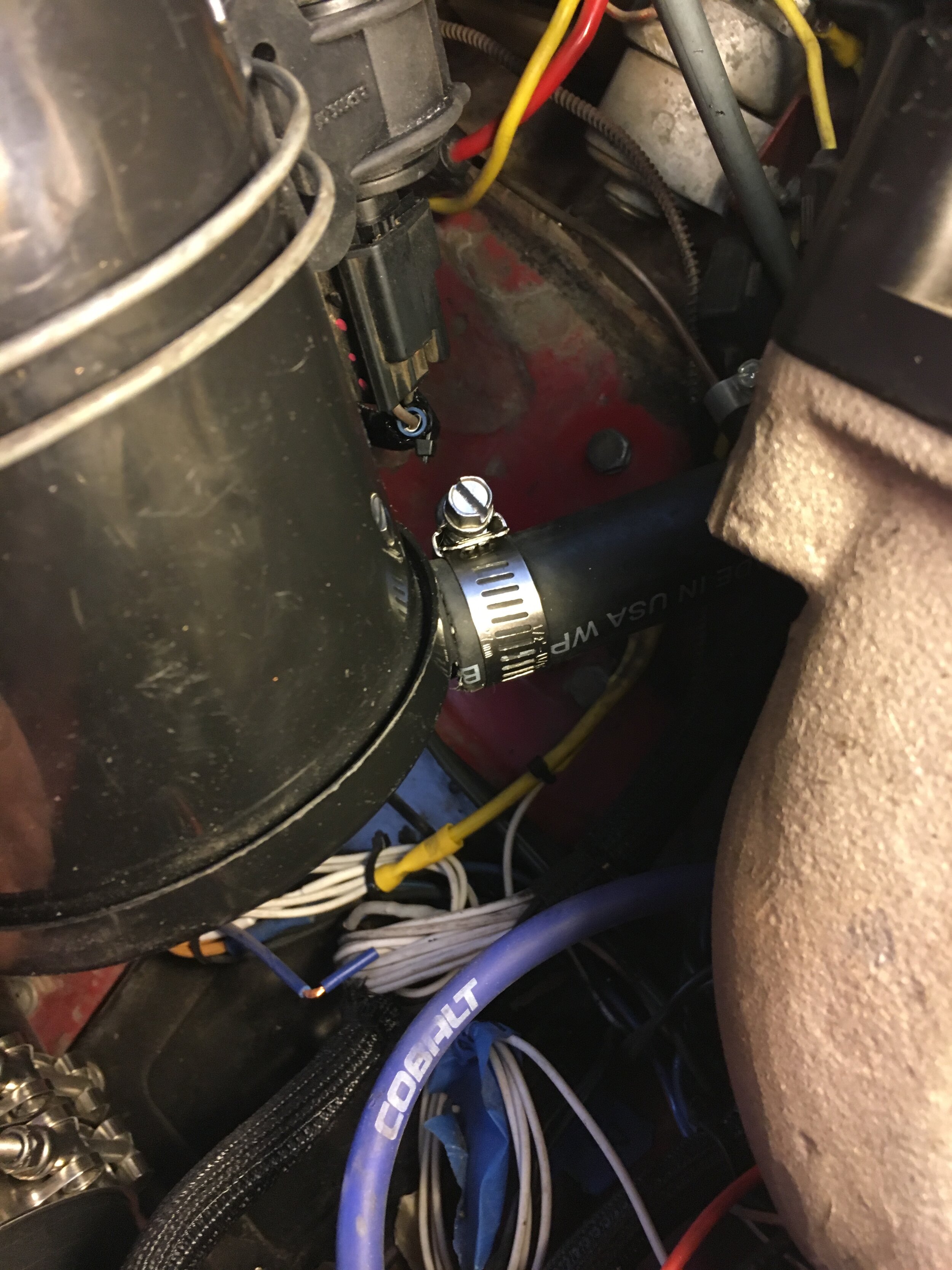
As shown here, the author elected to run the delivery line’s rubber hose up through the motor mount to avoid clutter and provide additional protection:
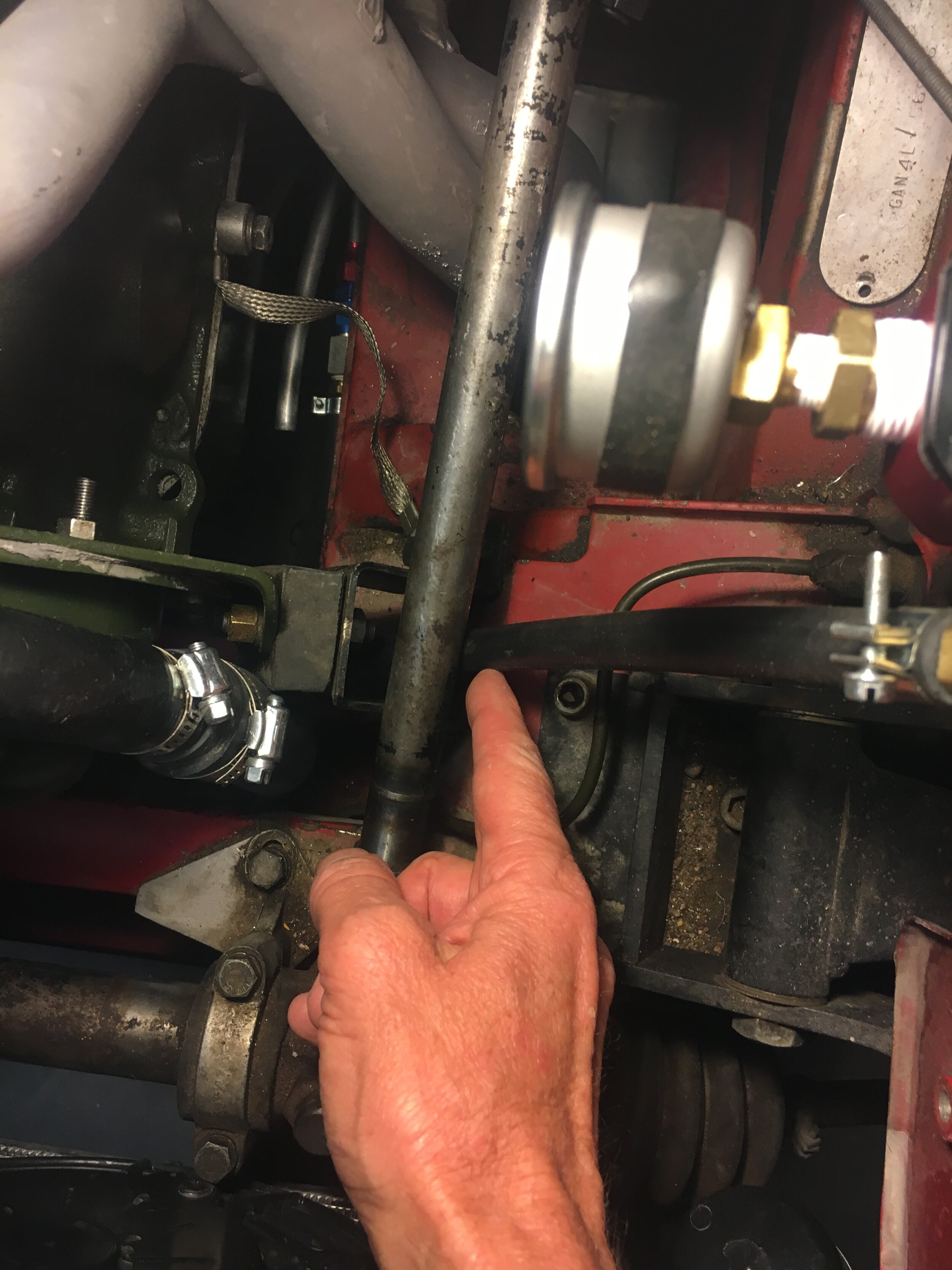
*Installation note: if you choose to mount your regulator to the inner fender as shown in these photos, be sure to read the section below on plumbing the intercooler (scroll down to the left-hand side discussion) and ensuring clearance between the carburetor snorkel and edge of the bonnet.
*Purchasing note: the diameter of the hose barb at the end of the delivery line must match the inlet of your chosen regulator. The universal Aeromotive regulator in the parts list can accommodate any size barb you wish (ours is 5/16” or 8mm); the OEM Metro Turbo regulator’s barbs are 5/16” or 8mm.
STEP 5 - Form the return line
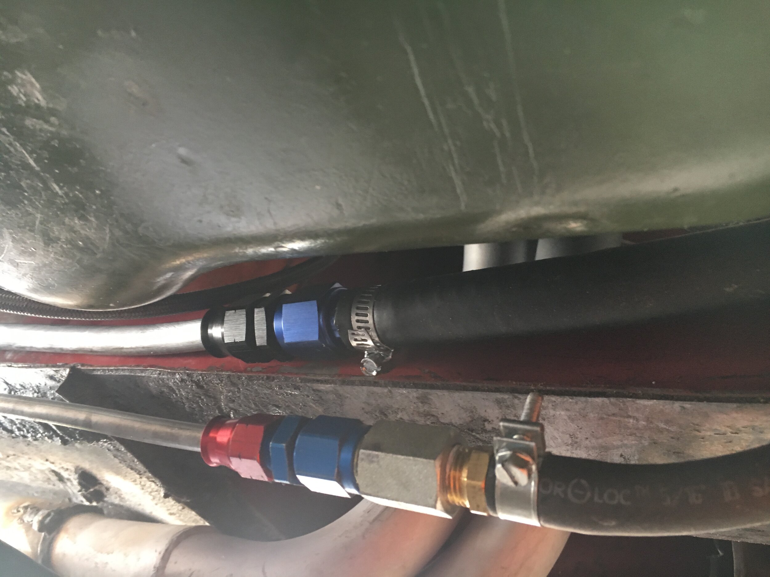
The procedure in this step is essentially the same as with Step 3, forming the delivery line. If you wish, you may alternate rubber and steel sections, as shown in Step 6 for cars running the Metro Turbo-spec pump and regulator. However, we prefer a single hard line passing out of the trunk (or boot) and leading all the way to the front of the car, as shown here. A short length of 1/2” rubber hose connects the hard line and swirl/surge tank, unlike the high-pressure delivery line, which is exclusively hard line all the way up to the engine.
Here is all you need to complete the return line, including the inexpensive spring bender and mini tubing cutter we used. The bicycle trainer drum is an arbitrary choice; PVC pipe or anything reasonably stiff that you have handy will work:

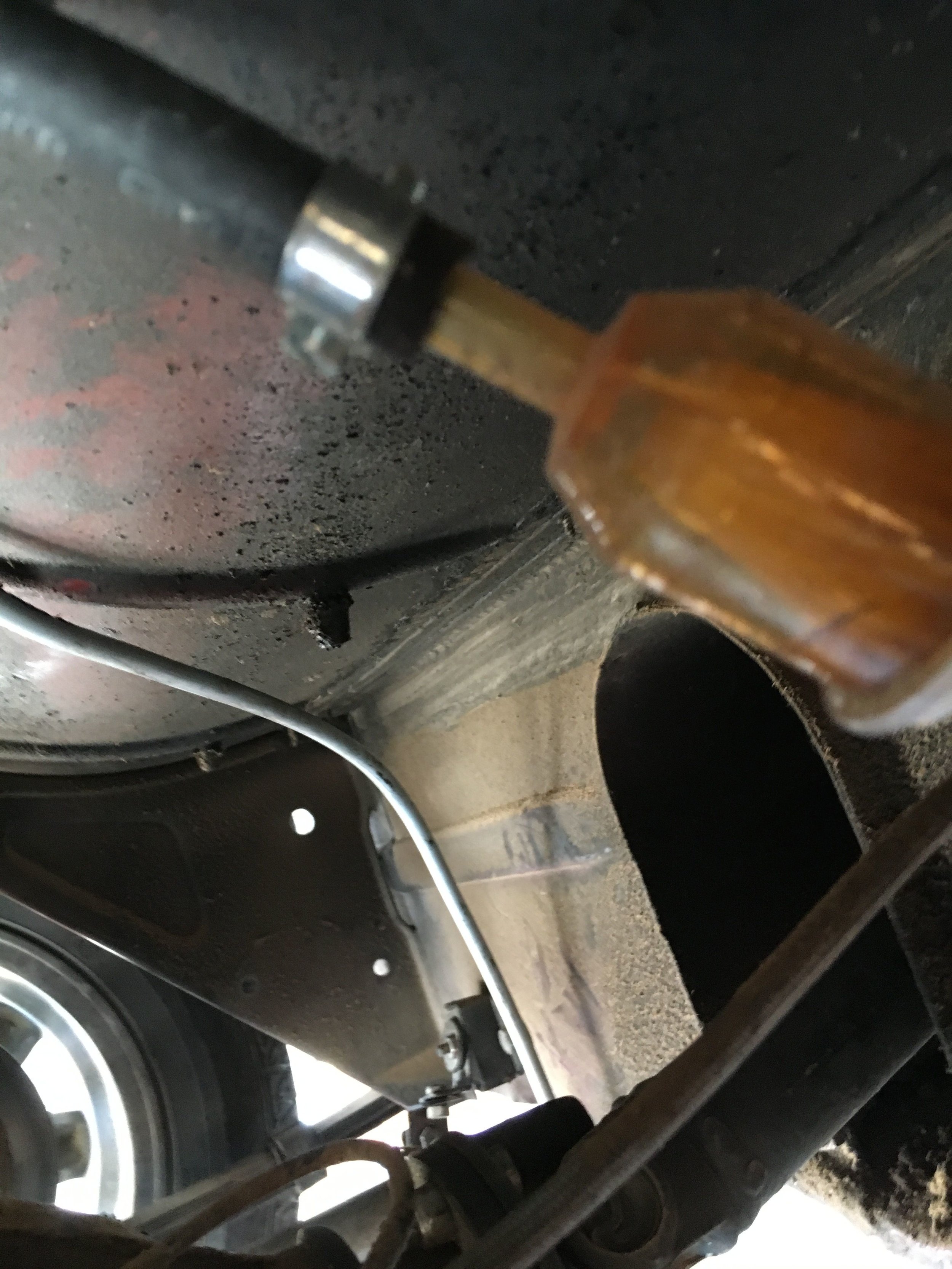
Begin by locating a convenient location for the return line hole and grommet. With our 1/2” return line, we chose to locate the hole several inches to the left of the high-pressure pump’s exit from the boot:
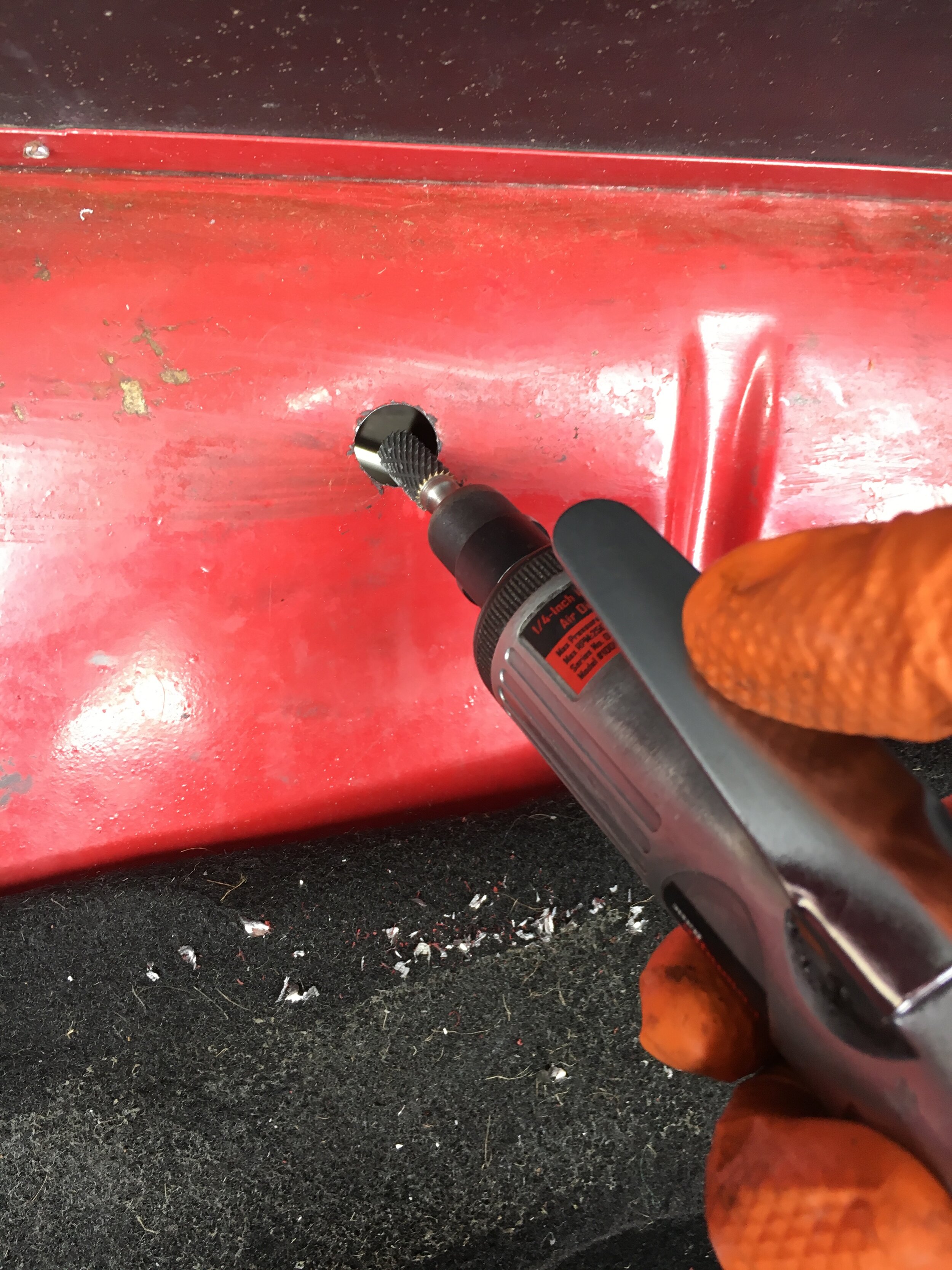
Next, dimple and drill the hole. The largest bit we had on hand was a 37/64” Silver & Deming, so we expanded the hole with a die grinder in a few seconds to match the grommet’s O.D., though you could use a round file or Dremel:
Now, measure a sufficient length to make the final bend toward the right-hand side of the car, scoot underneath, relax the coil just a bit to approximate the wheel arch radius, and pass the line into the trunk (boot):
Next, back to the boot. Carefully pull the line into the boot a little ways (the sharp edges of the steel can damage the soft aluminum line) and make a slight upward bend using the spring bender (or dedicated tool if you have one), followed by the tightest radius you can manage toward the swirl/surge tank. Finally, slide the line back through the hole and replace the grommet if necessary:

Now, scoot back under the car, adjust the arc of the line to match the wheel arch a little better, and use a sharpie to mark the midpoint of the tighter radius that will aim the line forward:

It may help to slide the line back into the boot slightly, but the trick now is to manipulate the coil so that you can use the spring bender and your radius form to make the tighter turn heading forward:

You may notice that the author encountered another difficulty, because of the crosswise positioning of the hydraulic mini-lift used for multiple vehicles. The solution was to torsion the line enough to slide the coil through the gap:
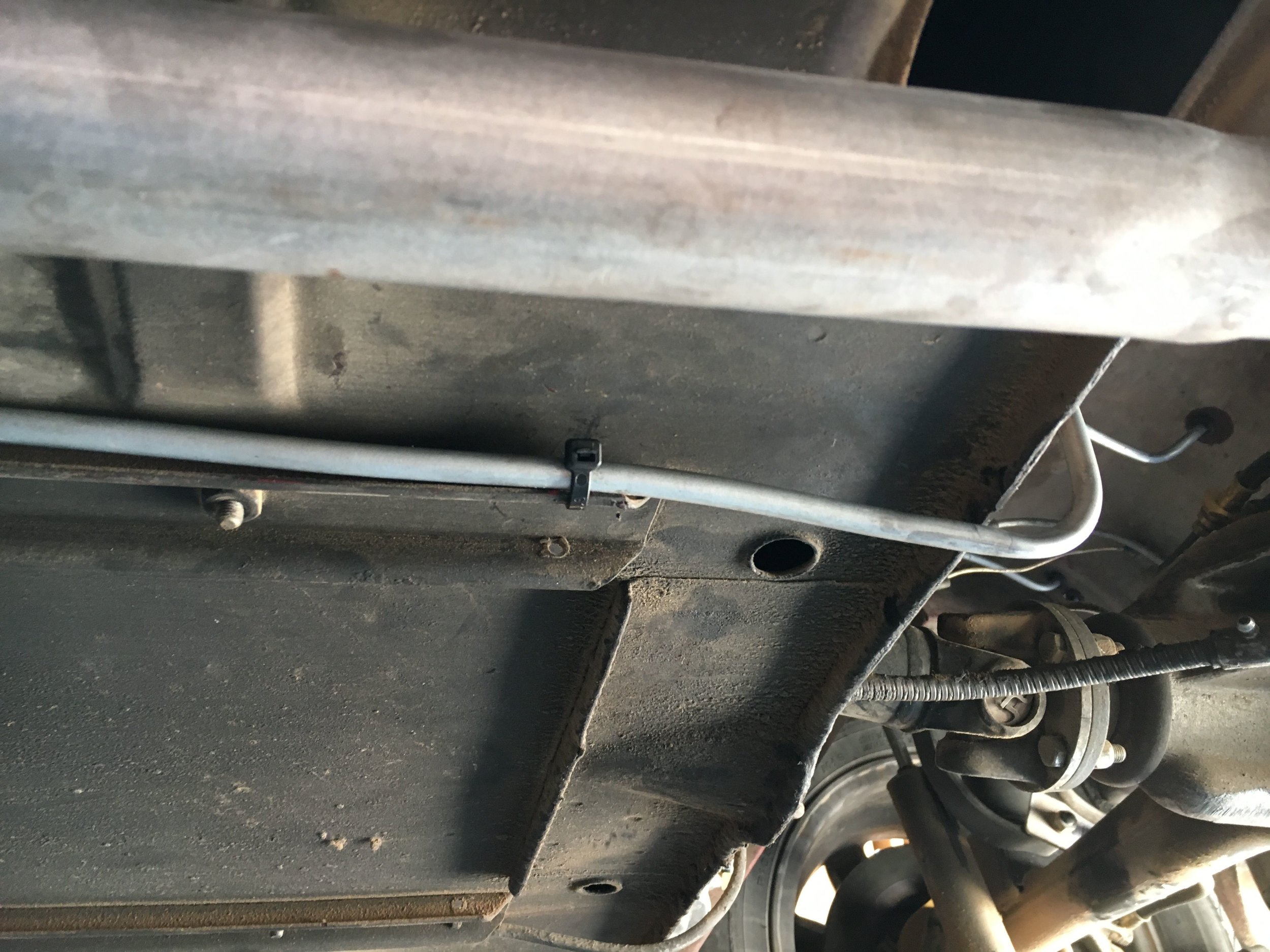
At any rate, unwind the coil sufficiently to form the straight run along the channel attached to the underbody and cut the line off where it reaches the large crossmember ahead of the oil pan. It may help to loosely hold the line in place with mechanic’s wire or relaxed zip-tie loops while you finish the bending.
Now, using the spring bender and your hands, finish the radius—making sure to return to the trunk/boot at intervals to ensure the final bend is in position:

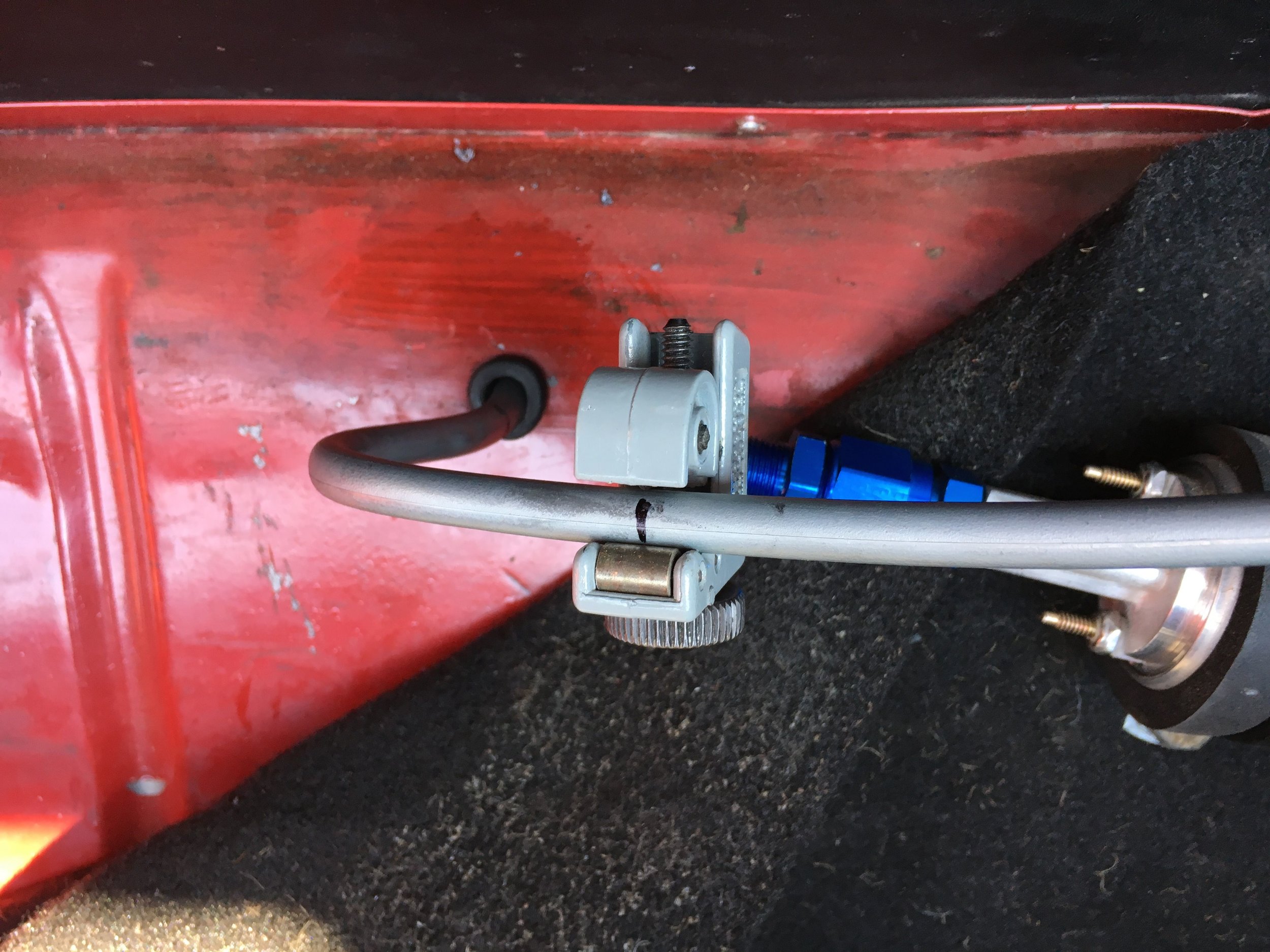
Finally, temporarily affix the line to the channel attached to the underbody pending completion of pillow block mounts clips, etc. (we will add a section on mounts soon). We slid pieces of 1/2” rubber fuel hose onto the hard line to prevent the steel channel from damaging the aluminum line in the interim:

Trim the return line at a convenient location, keeping in mind the net length of the AN-style fittings you will attach to the end:
Next, attach the 1/2” rubber hose (or whatever size your system requires) and pass it up through the motor mount to connect with the regulator. Notice that the return line does not need EFI-spec hose clamps and hose, but the high-pressure delivery line MUST use them:


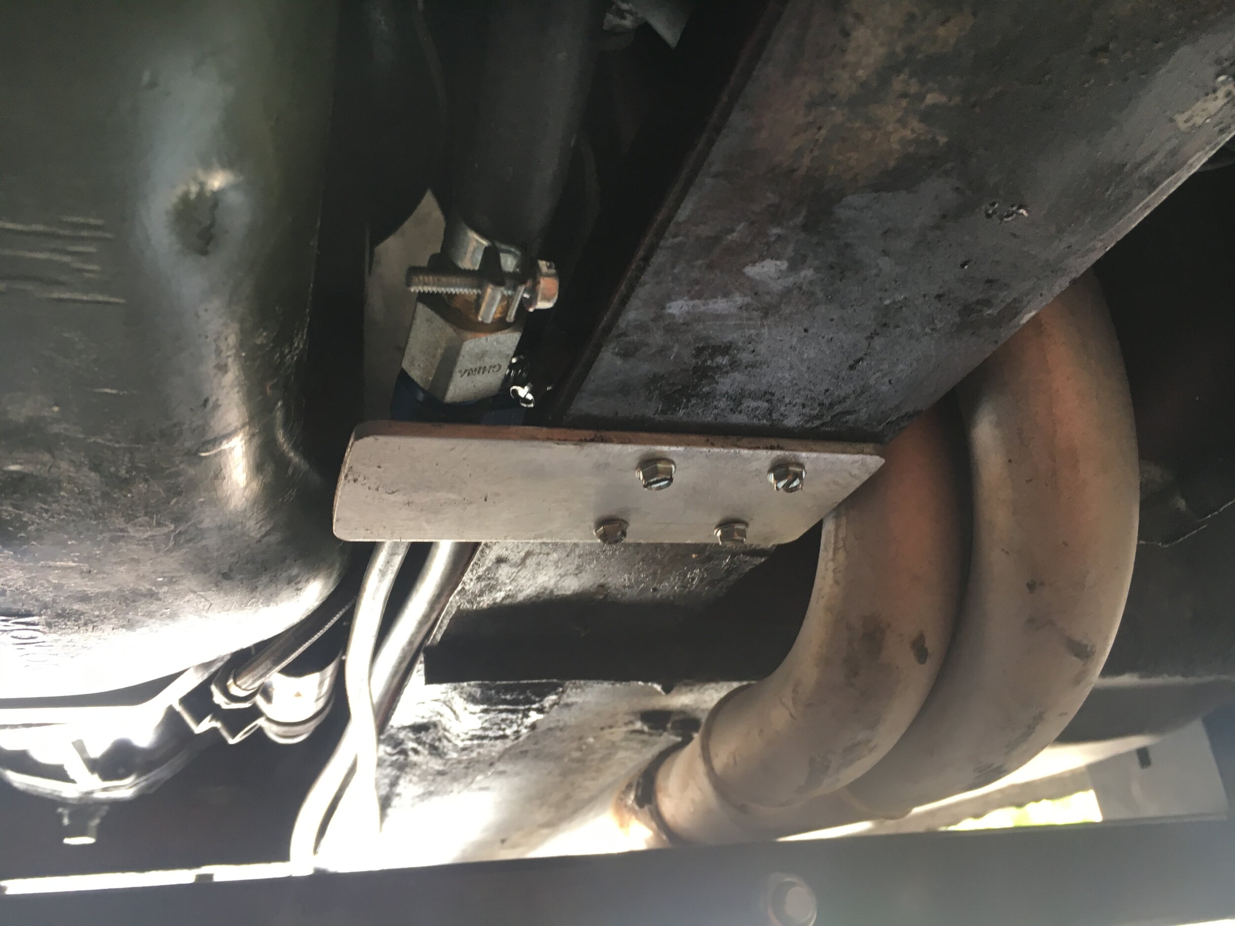
Now, tuck the lines up in between the frame rail and oil pan, and make up a simple aluminum bracket (we used home improvement store 1/8” bar) to keep them from falling down or riding on the oil pan and heating up:
STEP 6 - Form swirl/surge tank lift line and attach hoses
If you are using the Metro Turbo-spec pump and regulator, cut two pieces from the leftover 5/16” steel delivery line coil about 18" long, leaving the natural curve intact, then bend as shown in this series and insert through grommets and connect to the swirl/surge tank.
If you are using the Walbro EFI-spec pump and Aeromotive regulator, you will need one such 5/16” steel line for the lift pump, since you have formed a separate return line as set forth in the previous step. However, see the instructions for modifying or creating a vapor recovery system, which with early cars requires a hard line from the boot to the engine bay.
This series shows the twin 5/16” lift and return line setup for the Metro Turbo-spec pump and regulator:
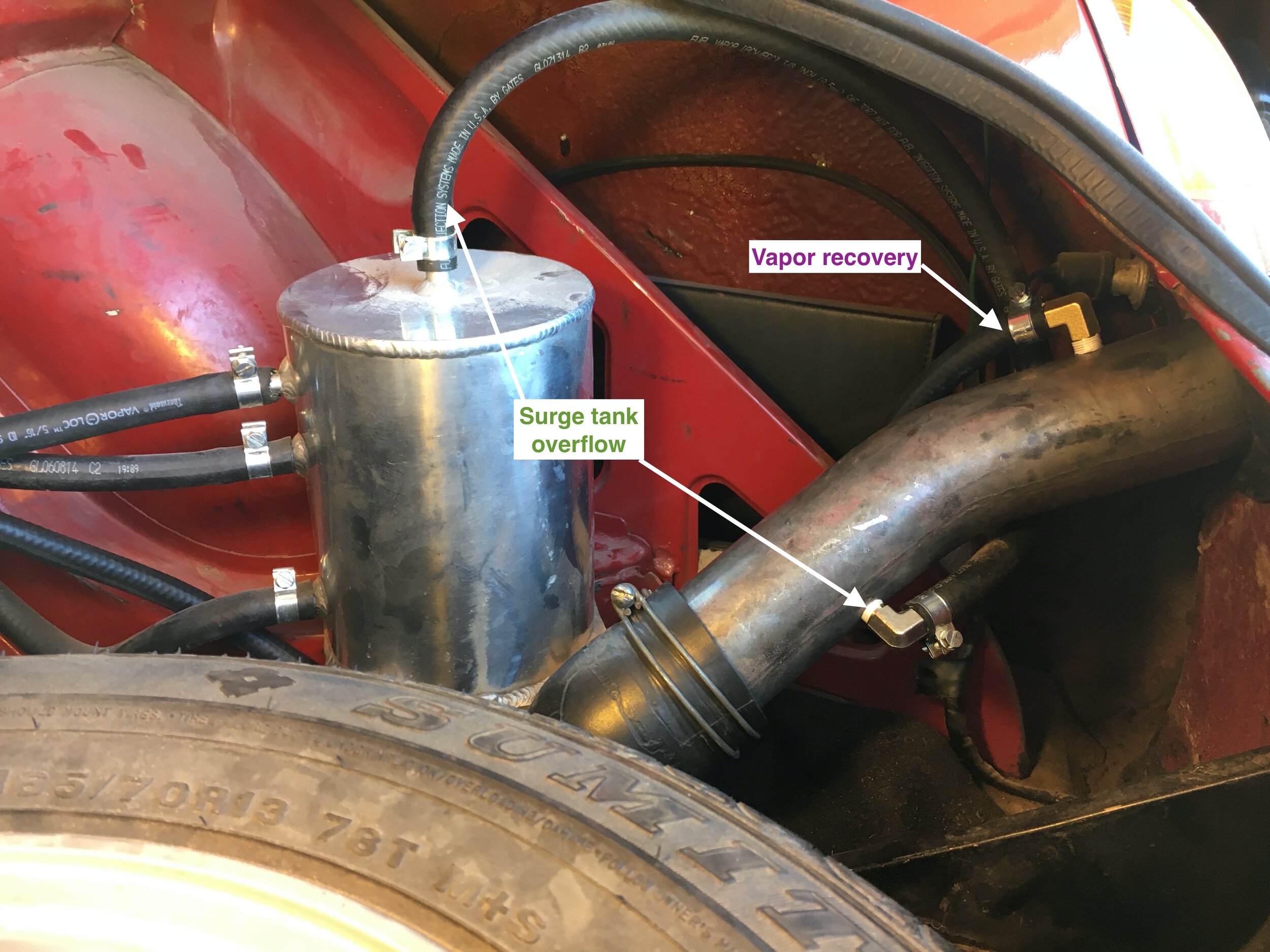
Here is a detail showing how the swirl/surge tank’s overflow line is routed to an NPT nipple screwed into a hole drilled in the OEM filler pipe. This aspect of the system is the same regardless of which pump and regulator you choose:

Here is a very tidy, alternate return line setup for cars with the swirl tank fitted under the bonnet:

Later model cars featuring a flexible filler hose may wish to insert the NPT nipple in the shorter length of steel pipe that passes through the bodywork. Doing so will allow you to keep your vapor recovery system intact.
Here is a video showing fuel emerging from the overflow inside the filler neck—and note that this initial test of the low-pressure lift pump and swirl tank overflow was done with the high-pressure pump’s power lead disconnected:
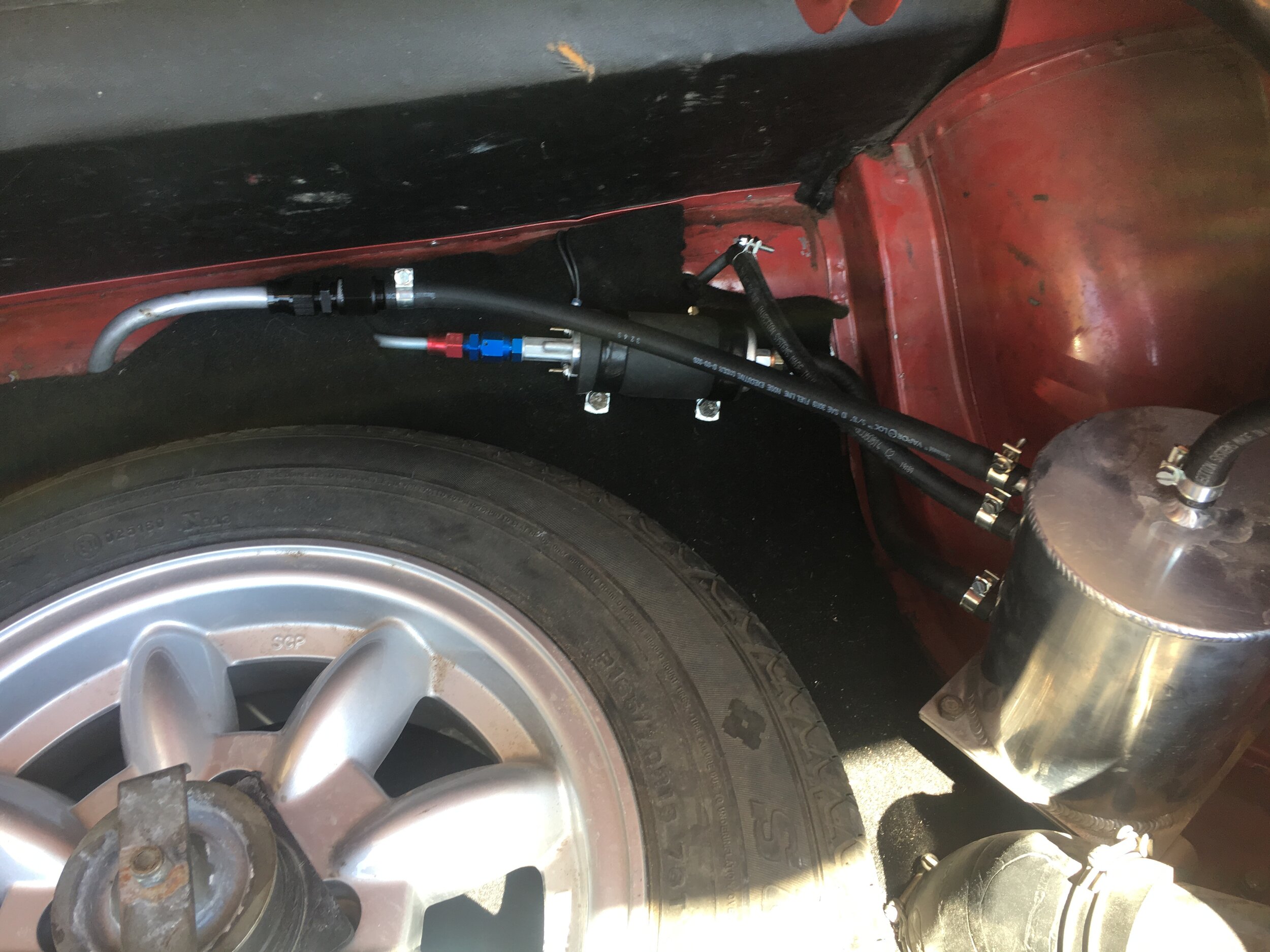
STEP 7 - Plumb the Return Line & Low-Pressure Fuel Pump
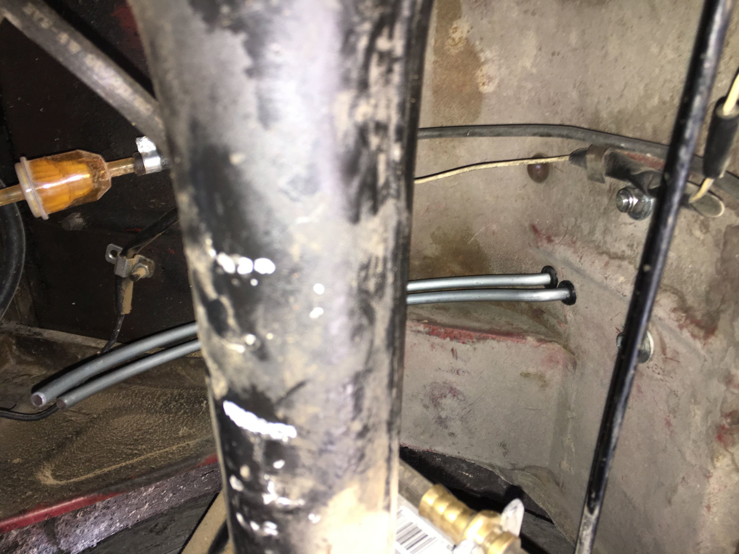
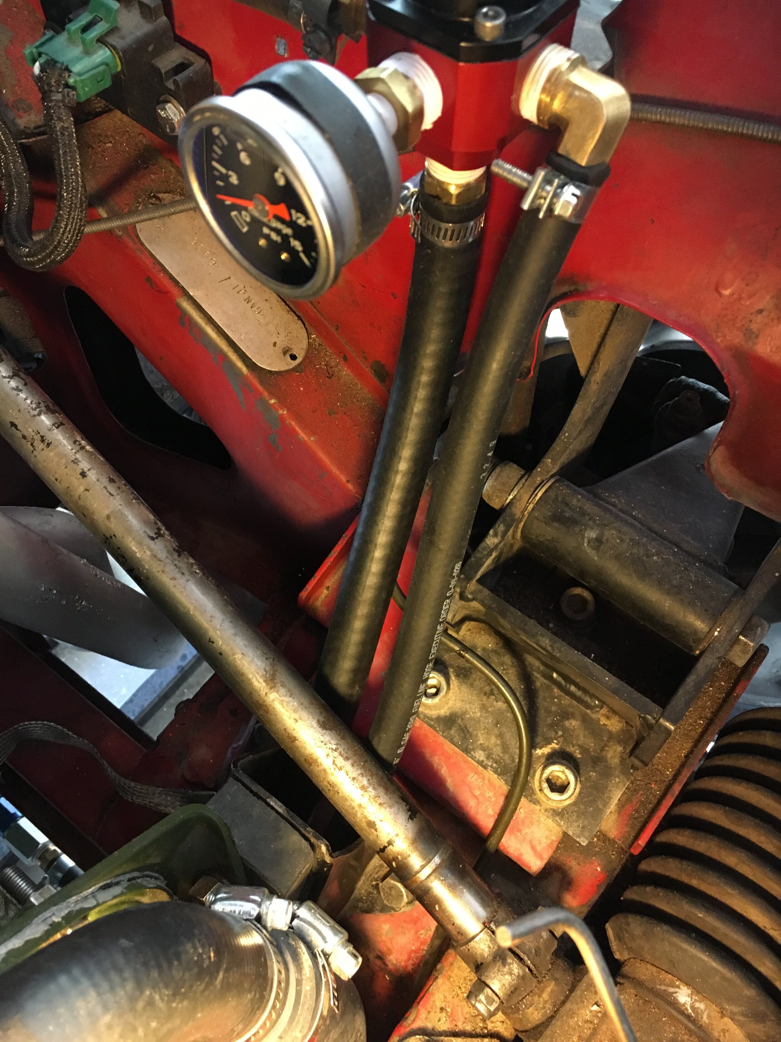
The '1967 MG Midget test mule was run naturally aspirated while the balance of the conversion was completed in stages.
Here is how the lines discussed above were configured in the interim—and note that this photo shows twin 5/16” steel lines passing into the trunk/boot, which is for either Metro Turbo-spec setups or one of them may be used for the vapor recovery line per the following section if your 1/4” OEM delivery line is removed:

All that remains with this Metro Turbo-spec setup when you are ready to operate under boost is to swap the rubber hoses around.
With the Aeromotive regulator and Walbro pump, a 1/2” return line is necessary as discussed earlier. Just take the rubber hose that used to connect to the 1/4” delivery line and attach it to the 5/16” formed steel line leading into the boot.
Here is a series showing the AN-style fittings being attached to the return line in the boot. We attached an 8-AN to 5/16” hose barb, but you may use a 3/8” or 1/2” barb —so long as you do not reduce the orifice leading into the swirl tank smaller than 5/16”:
Again, you can run naturally aspirated once the high-pressure system is installed and the regulator adjusted as set forth in the following section.
Create or Modify an Existing Vapor Recovery System
When the car sits after an extended run at freeway speeds or in stop-and-go traffic on a hot day, the fuel will expand and vapors accumulate in the tank and in the carburetor float chamber. The filler cap on early cars allows air in but not out, so the tank may become distended from the pressure, and the car slow to start.
*Note: if the engine does not fire immediately, hold the throttle fully open while cranking the engine to clear the excess vapor from the intake manifold.
While it is not a complete cure for ‘vapor lock,’ the system used in many late ‘60s British cars discussed in the following video by John Twist does eliminate pressure build-up in the fuel tank and release of fumes into the garage:
The steps needed to add or modify a vapor recovery system to work properly with a blow-through setup (turbocharged or supercharged) are straightforward, but vary depending on whether you have an early or later model car.
EARLY CARS
STEP 1 - Plumb a Fuel Tank Vapor Recovery Line
Use either the existing 1/4” OEM fuel delivery line or the rest of the coil left over from the 5/16” high-pressure fuel delivery line to serve as a vapor recovery line:
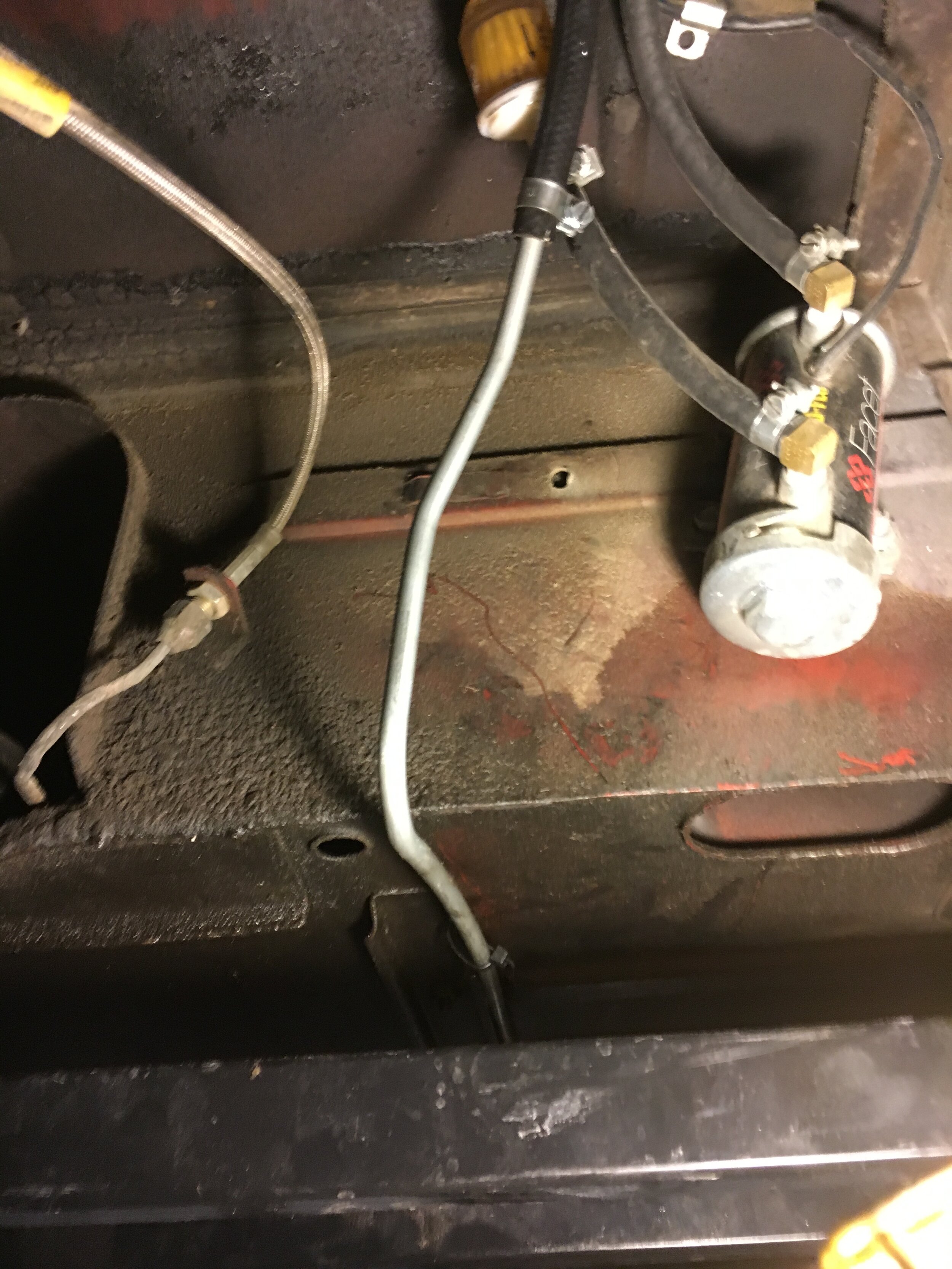
In the boot, the vapor recovery line is connected to a 1/8-27 NPT x 5/16” hose barb elbow inserted in the fuel tank filler neck—located on top of the neck and above the other elbow for the overflow from the swirl/surge tank:
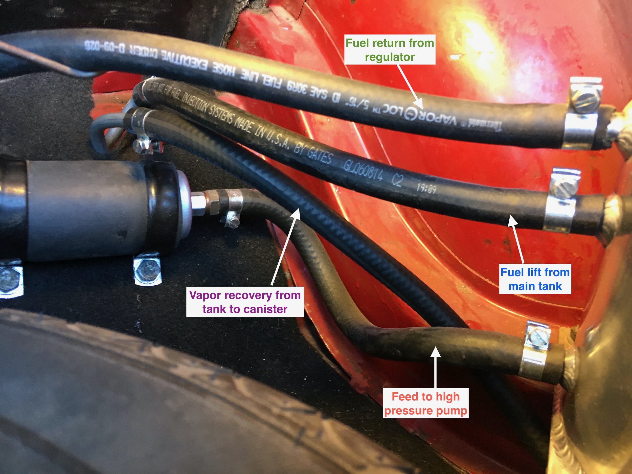
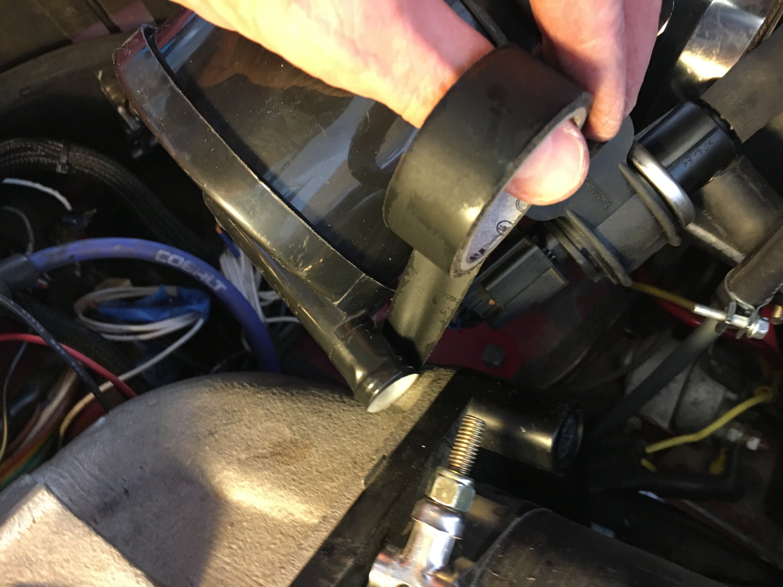
In the engine bay, the vapor recovery line is connected to a standard MG charcoal canister. The second nipple connects to the valve cover as discussed below, while the third nipple is capped (because the carburetor float chamber cannot be vented into the atmosphere to retain boost pressure):

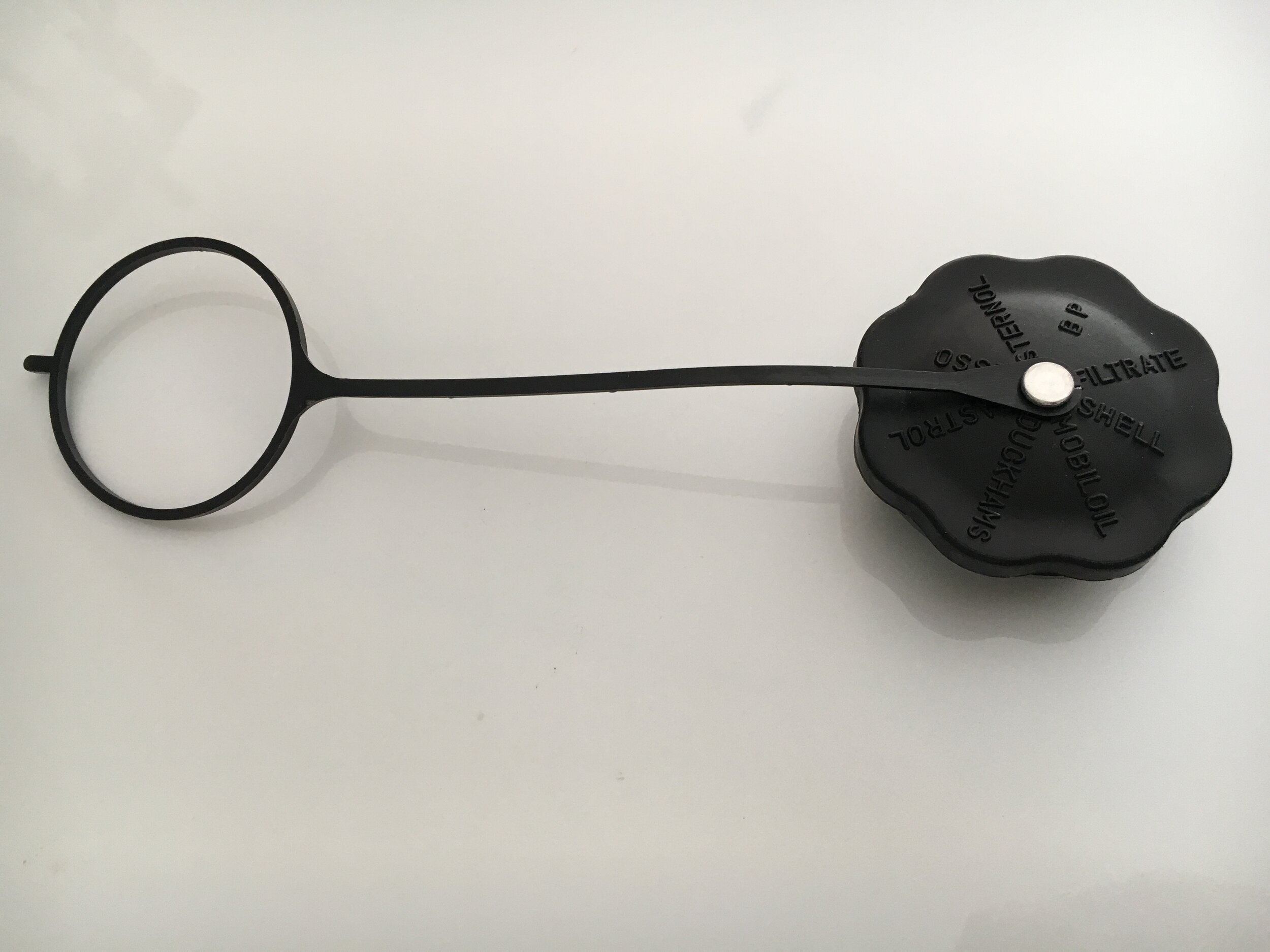
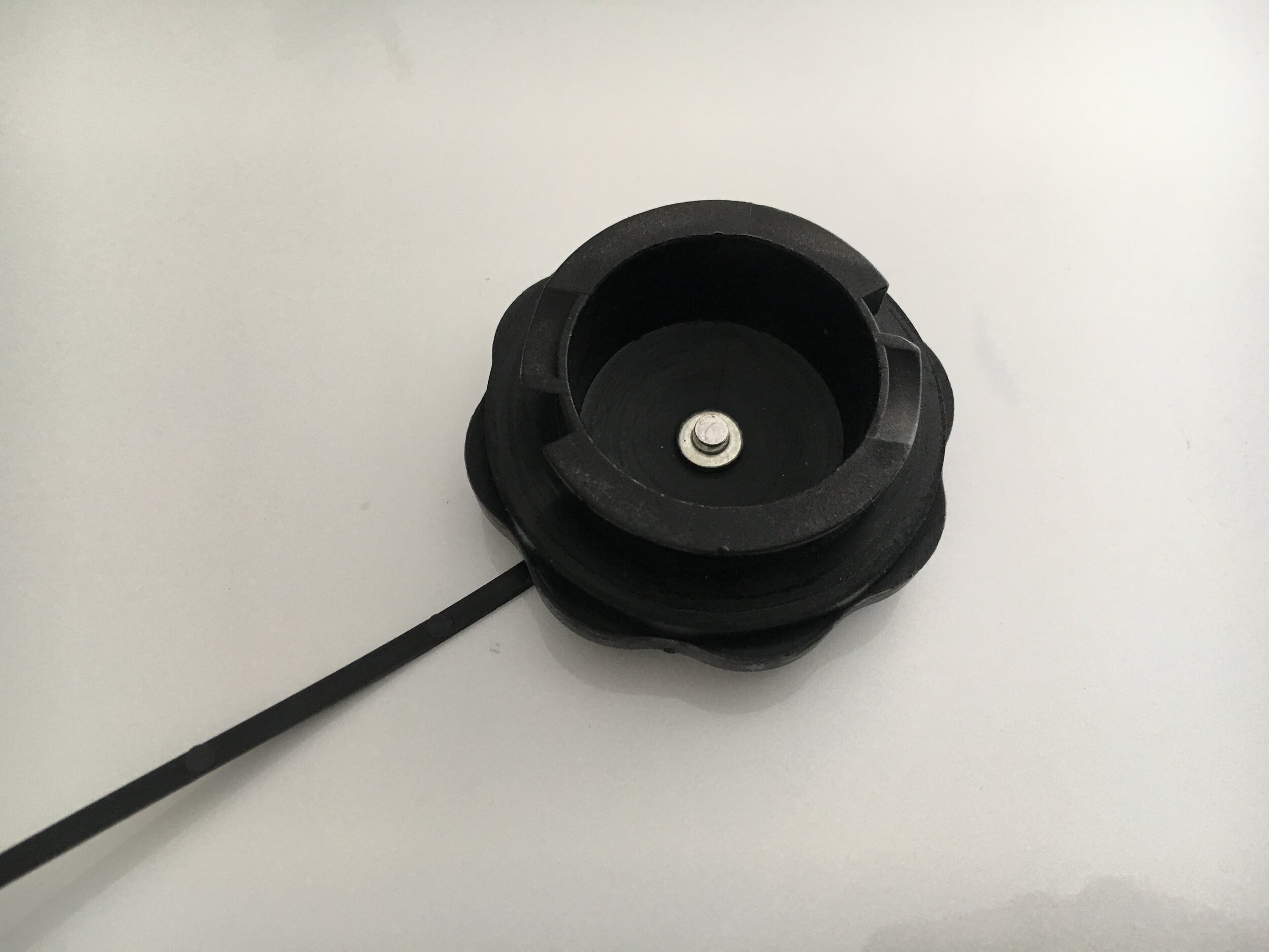
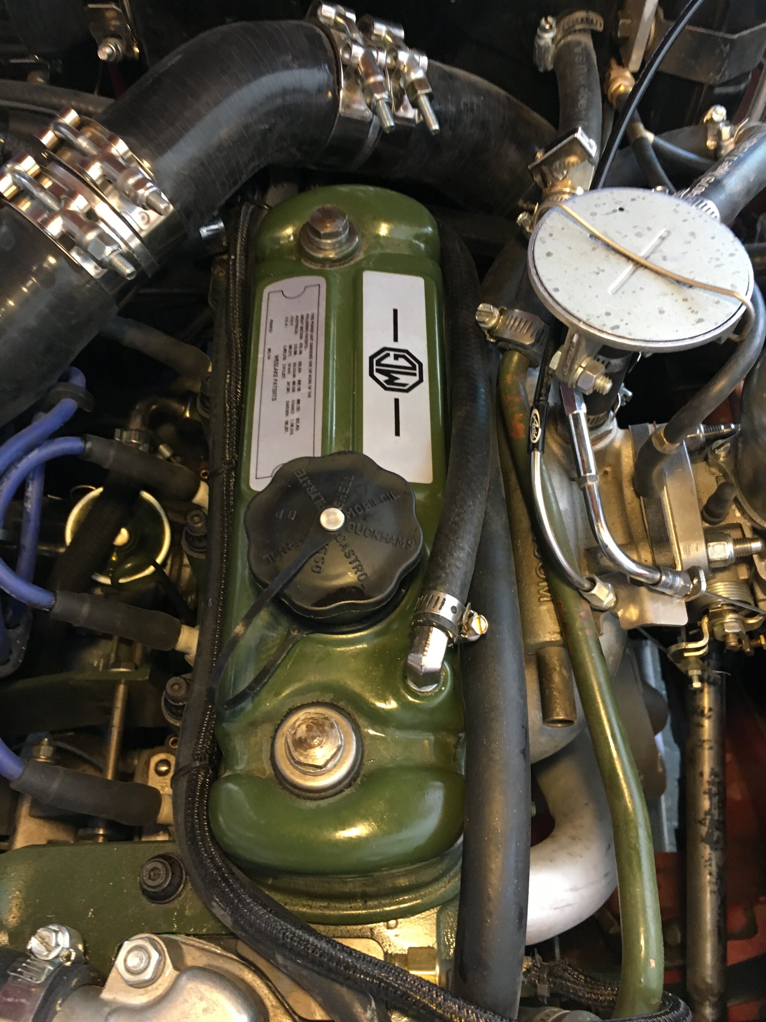
STEP 2 - Install a Non-Vented (sealed) Oil Filler Cap
The vapor recovery system uses the modified, two-stage PCV system to draw fuel vapor stored in the charcoal canister through the engine via the valve cover (as discussed in the next section).
Therefore, you must install a non-vented or sealed oil filler cap like the OEM version below (Moss # 460-125), or an appropriate sealed cap for your aftermarket valve cover:
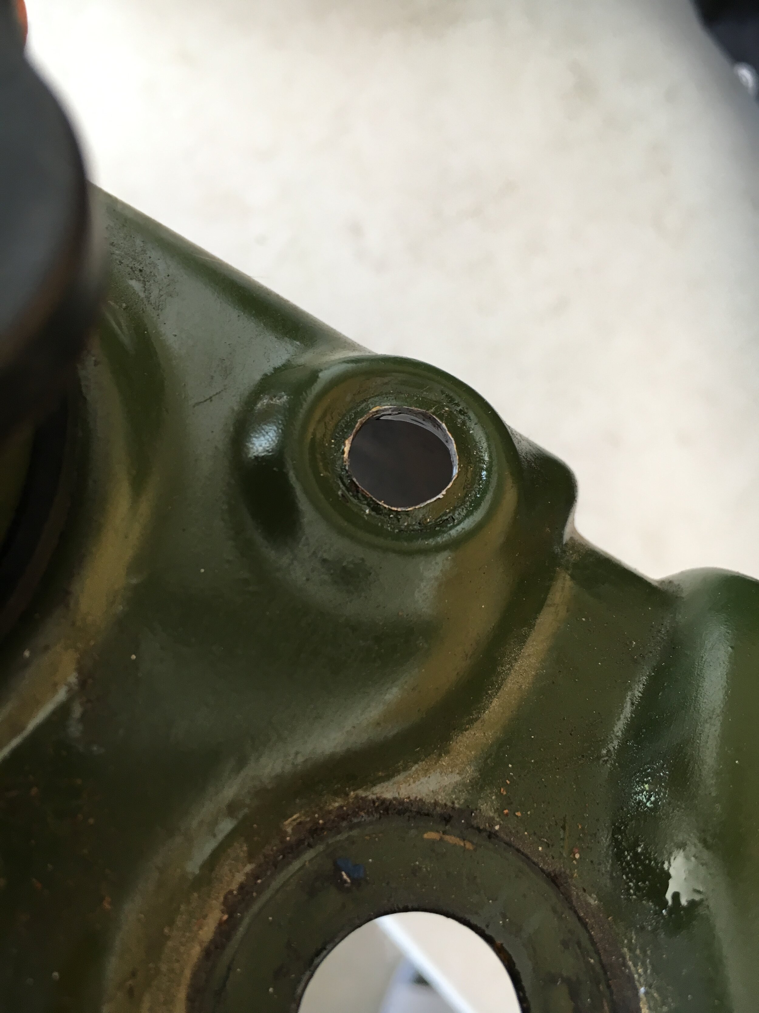
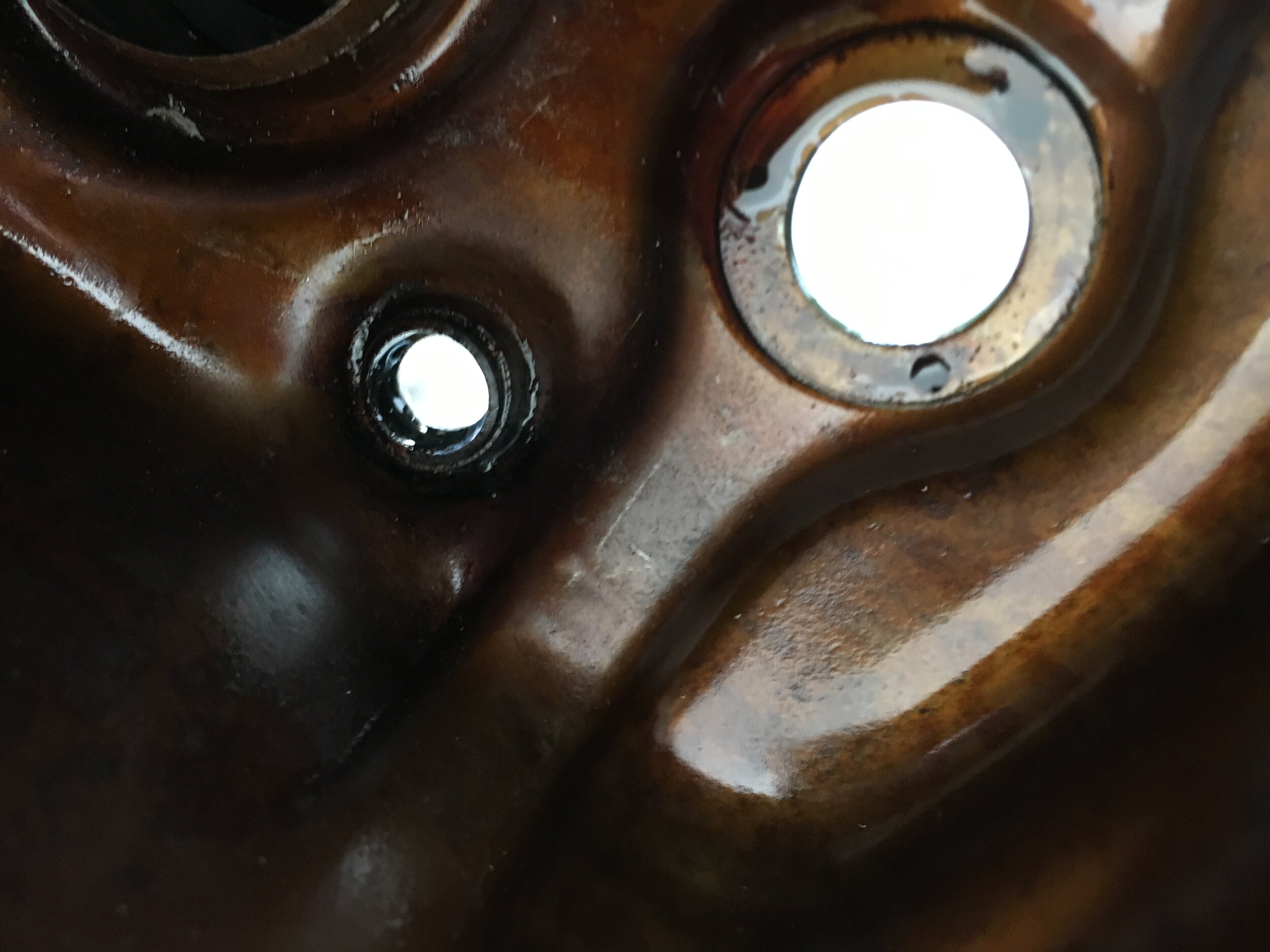
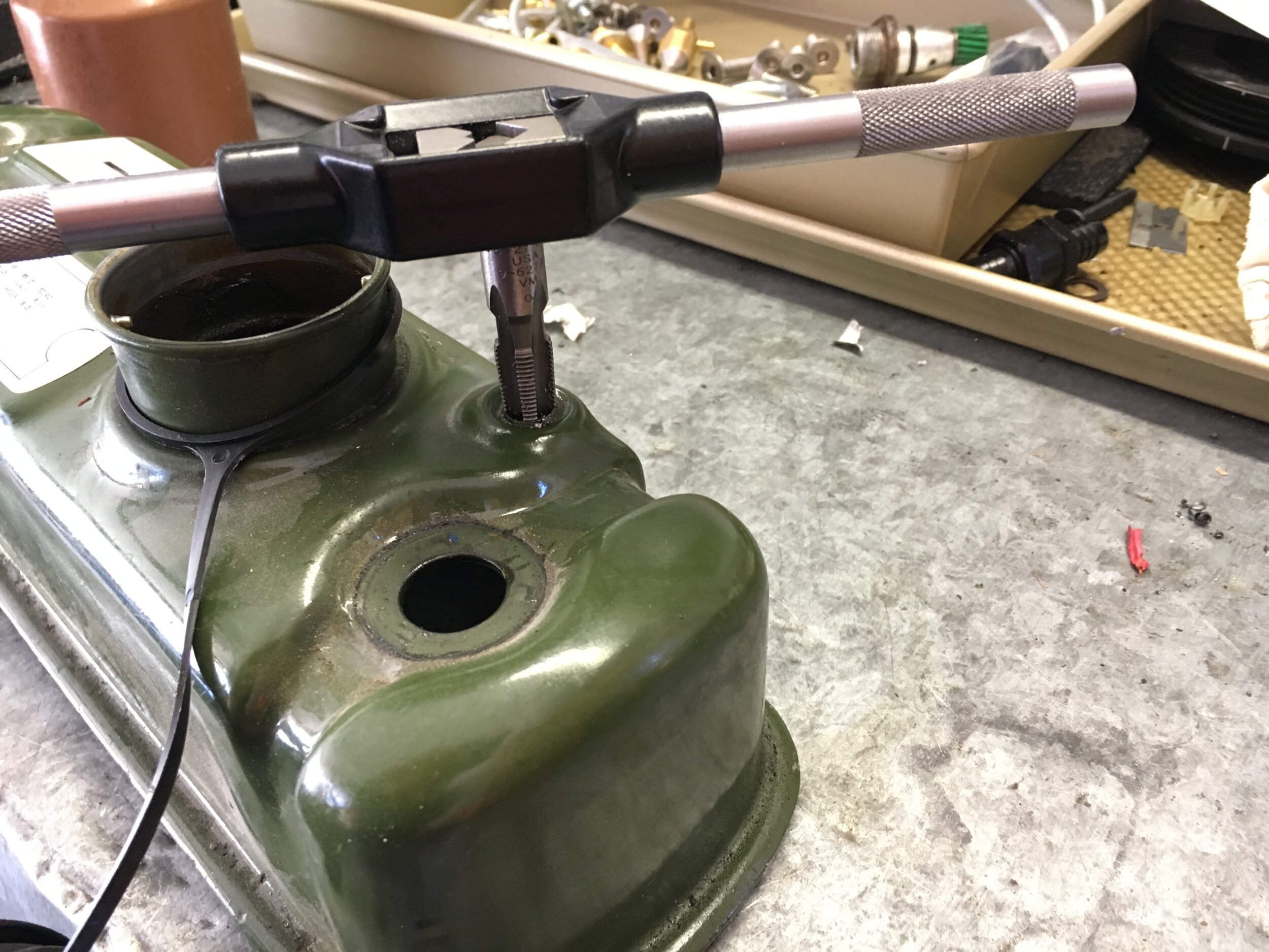
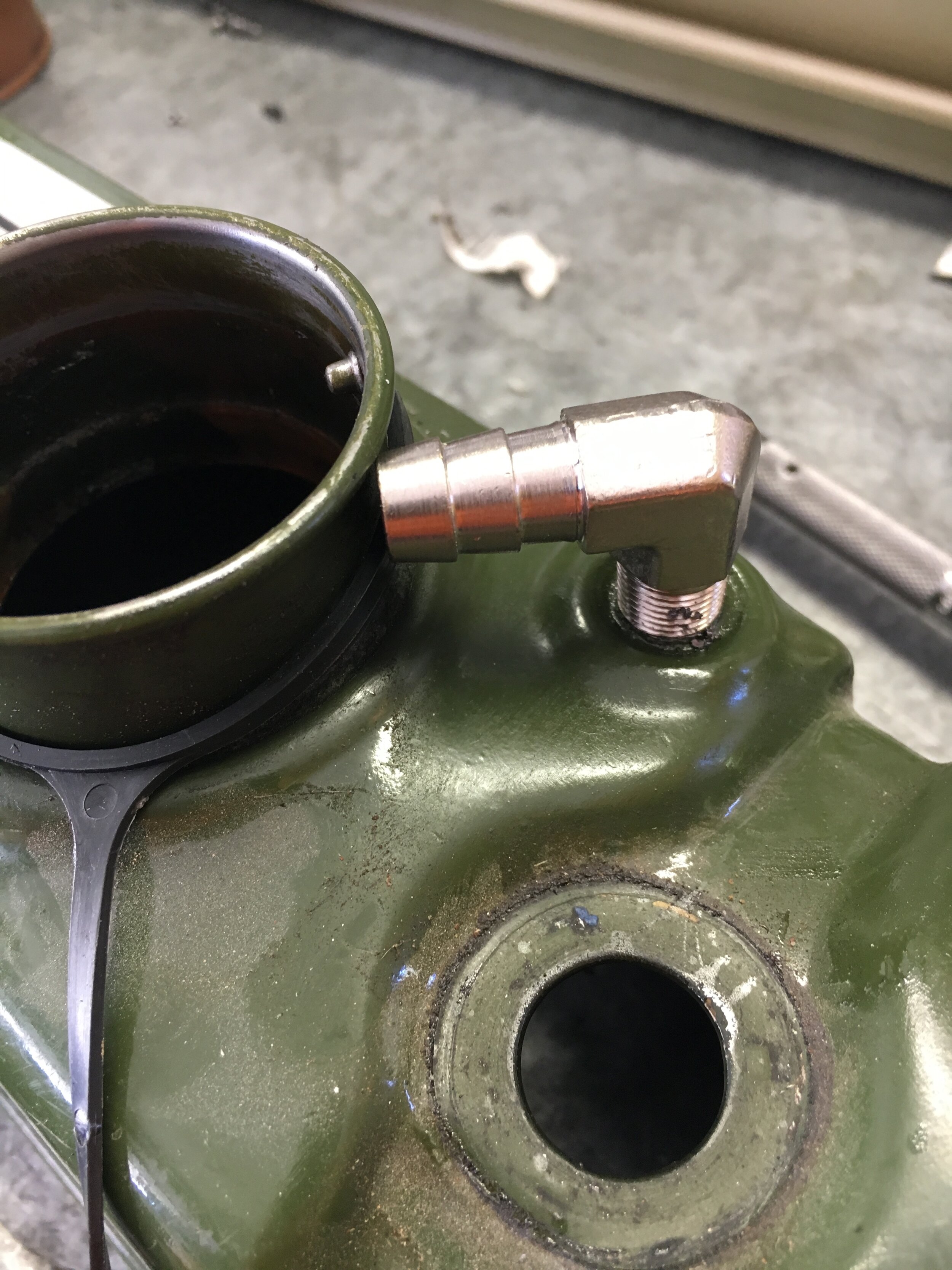
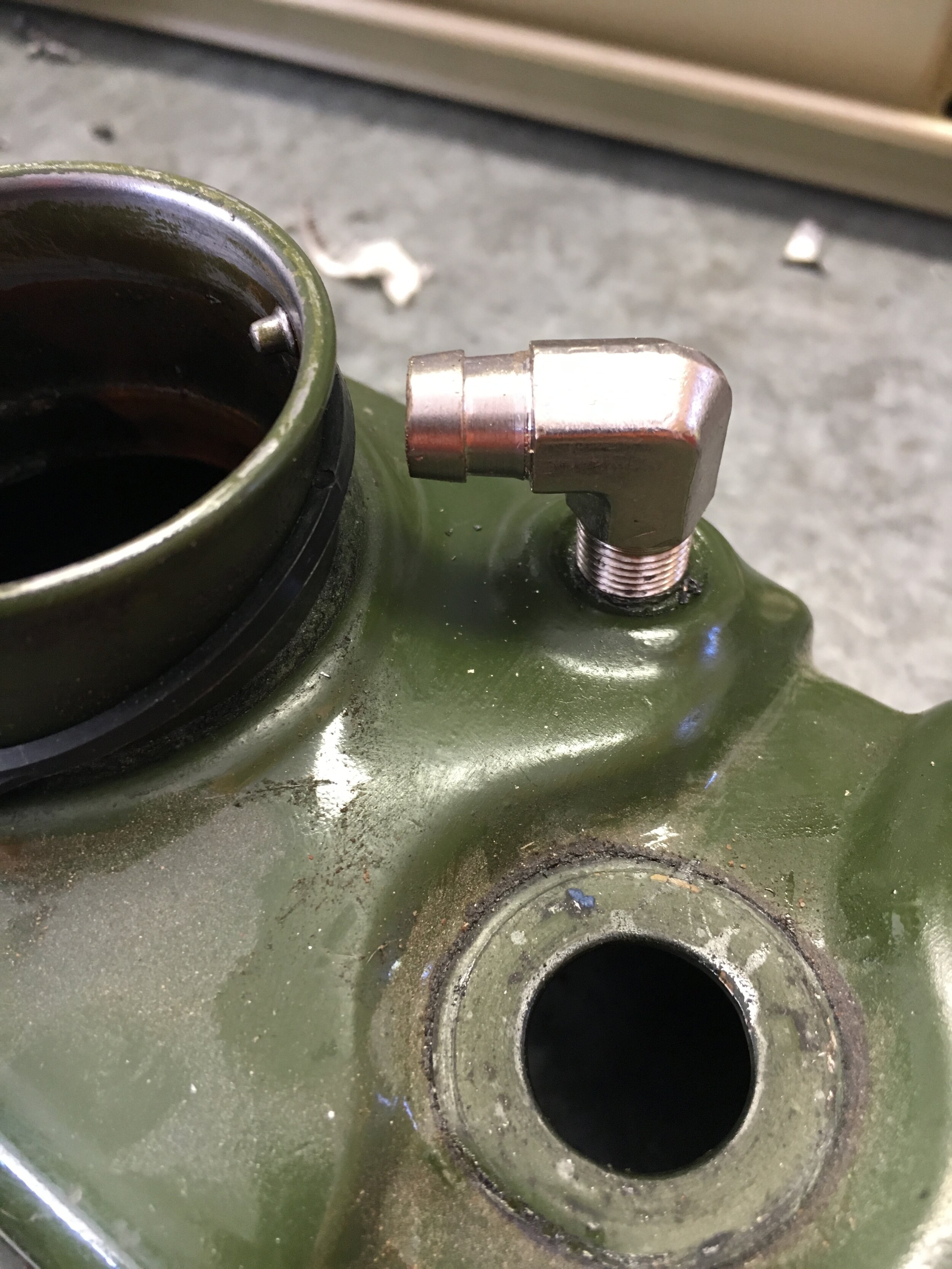
STEP 3 - Install and Plumb a Fitting in the Valve Cover
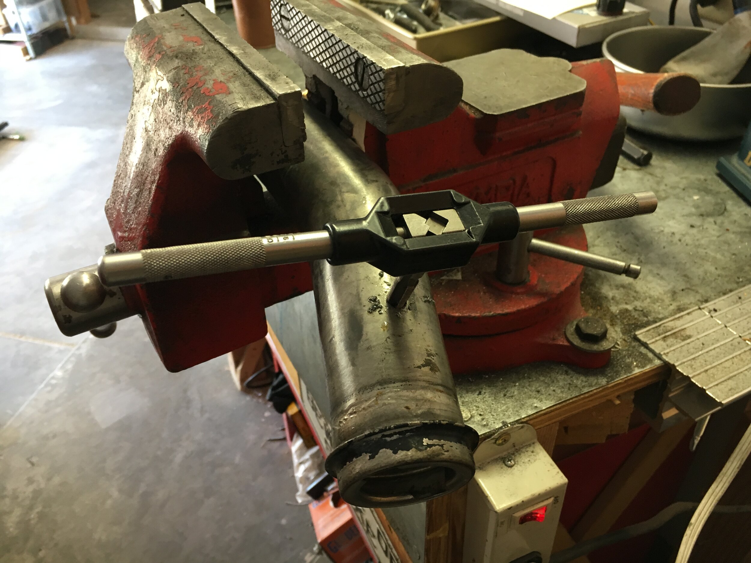
Unless you already have a fitting attached to your valve cover that features an internal restriction from 7/64” to 1/8” in diameter, drill and tap the existing blanked-off port to receive a 1/8 NPT elbow with a 3/8” hose barb. The barb may have to be trimmed slightly to clear the oil filler neck:
We discovered that the 1/8” to 3/8” reducer in the following photo series (available in brass or stainless steel) has an I.D. of 7/64”, which is the correct restriction to recreate proper metering per the OEM system.
Just slip it into a drill motor and hold a flat file against the lip (orient the cutting teeth against the direction of rotation) to reduce it to the O.D. of the adapter in a few seconds, then insert into the hose with the small nipple facing the valve cover:
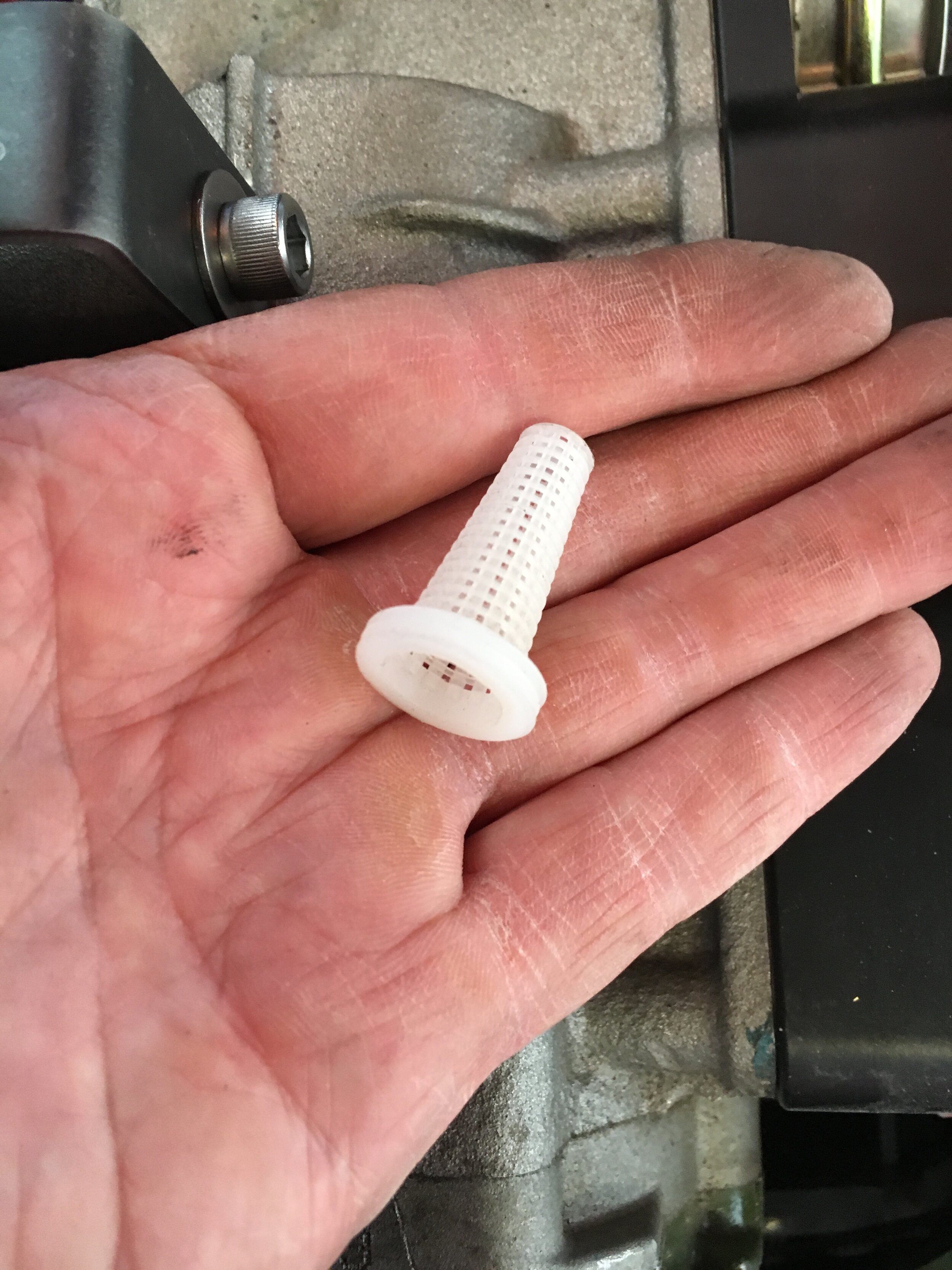
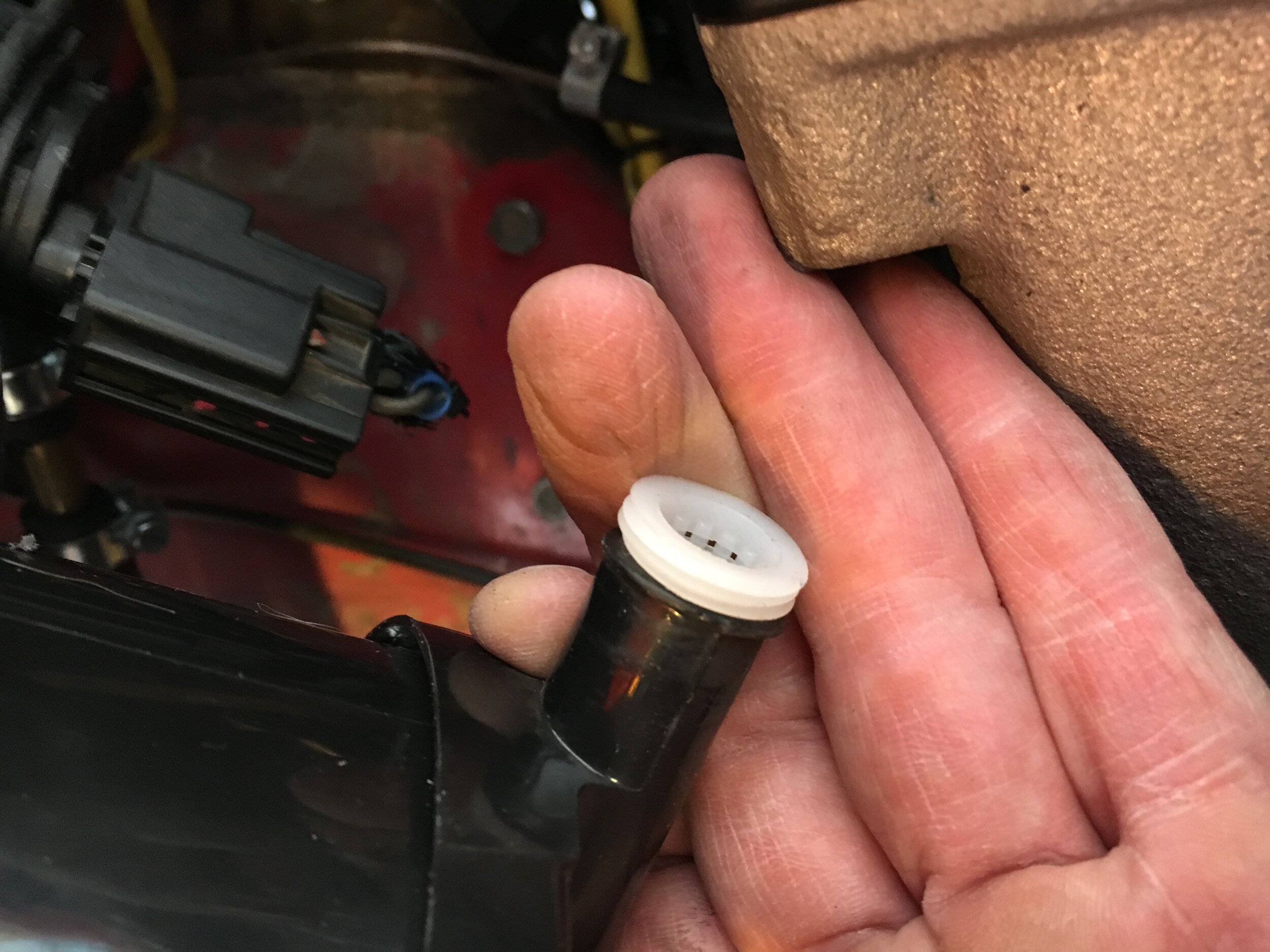
*Note: the replacement charcoal canisters available may not have a screw-off bottom, and the foam used to retain the media may break down, allowing charcoal to spill out the large hose at the bottom.
The fix is simple. Just take a drip irrigation filter cone, insert it into the bottom hose barb, apply some electrician’s tape, and slip on the 3/4” hose leading down to the road:
plumB and adjust the pressure regulator
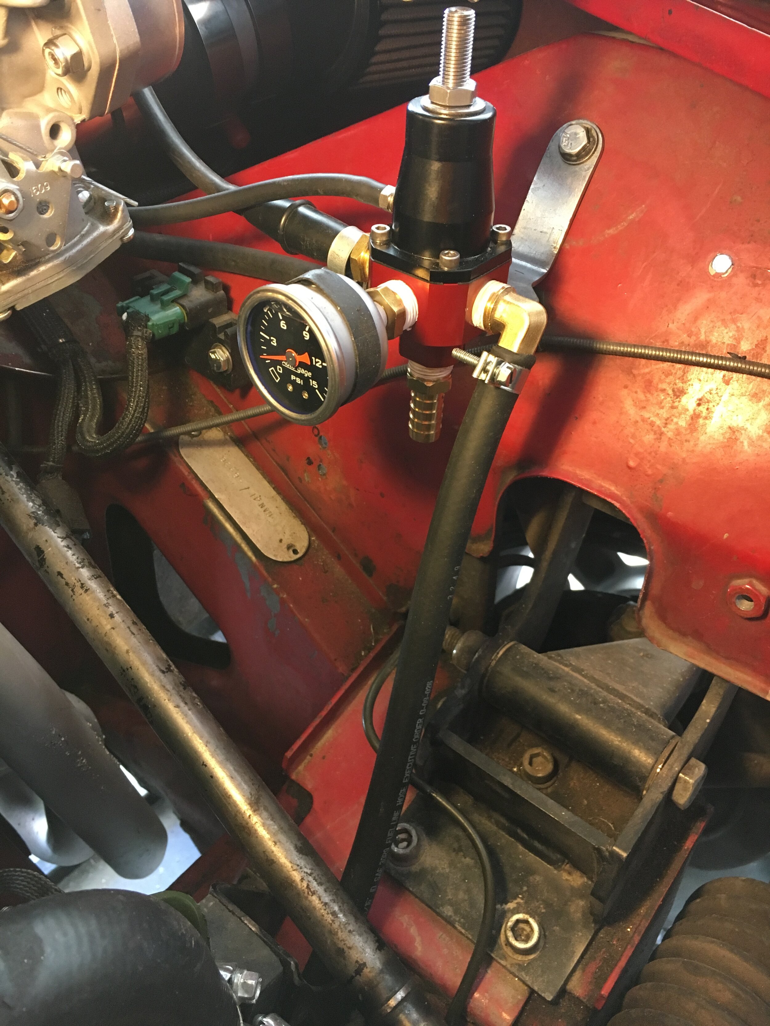
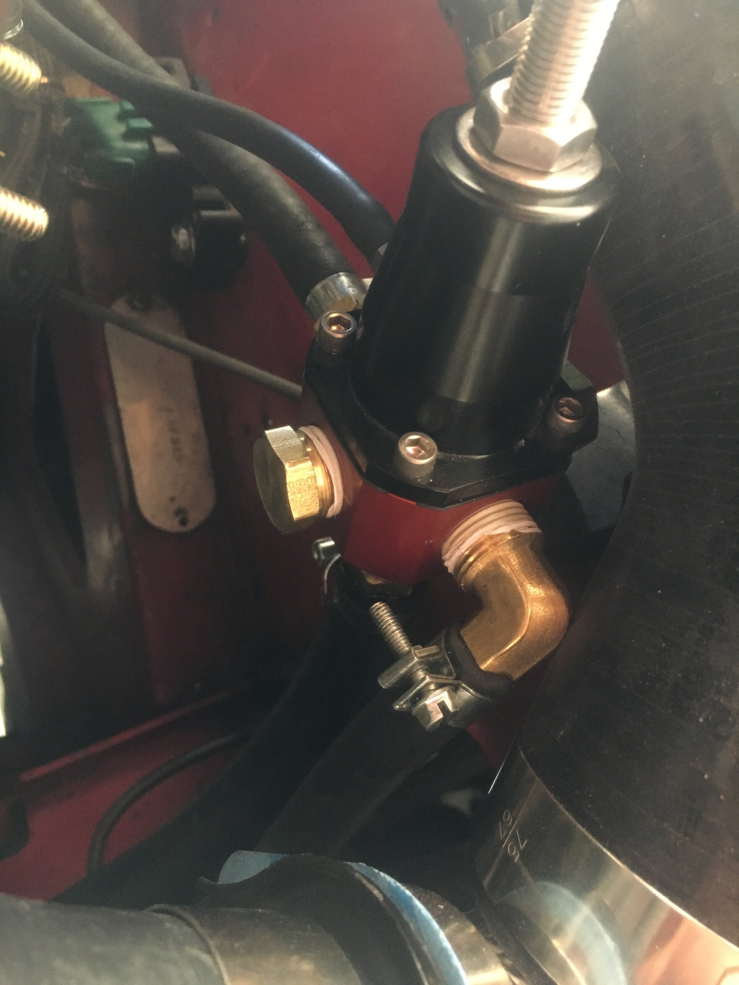
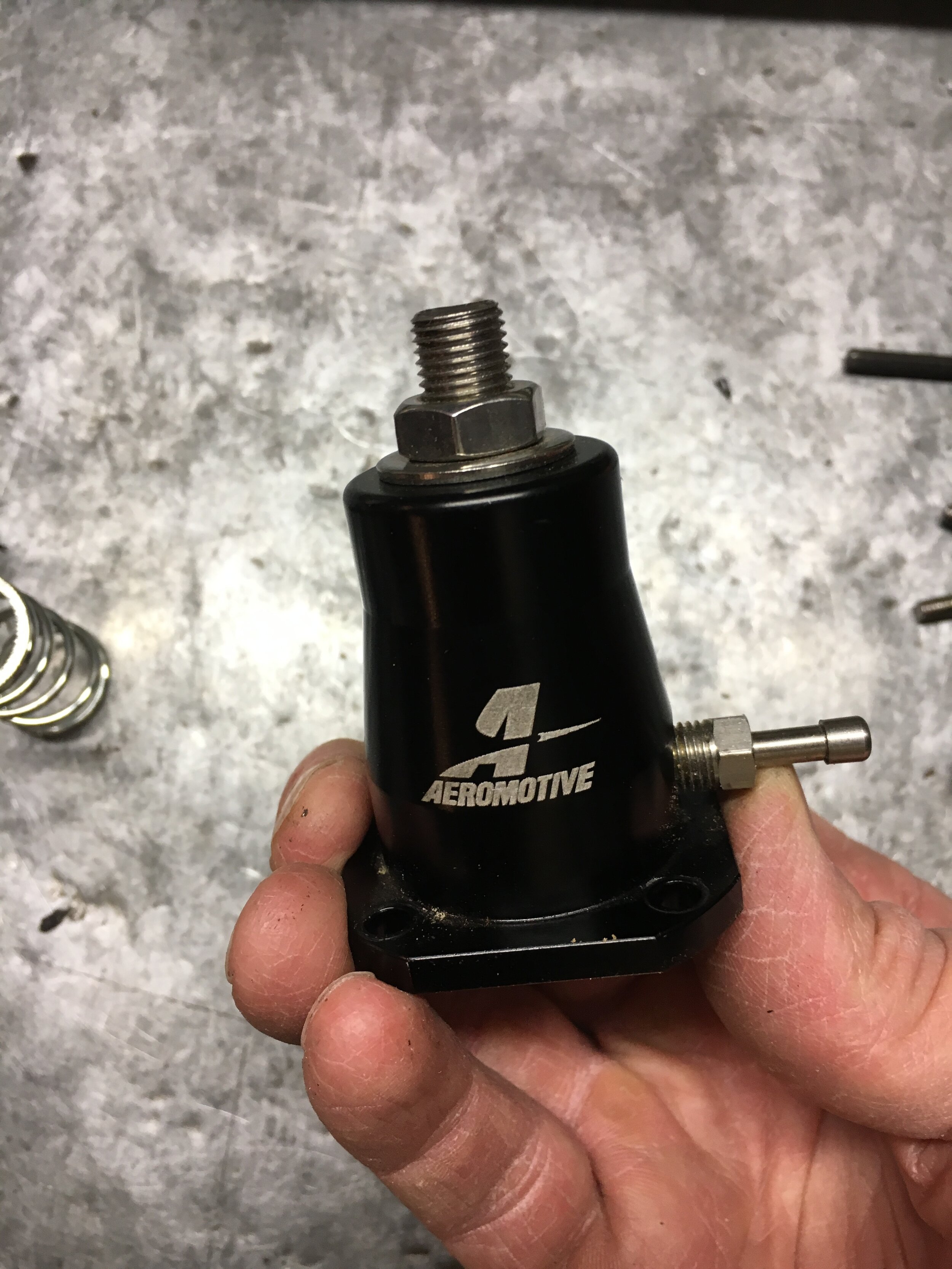
A suggested location for the fuel pressure regulator is shown earlier (but see the section below on plumbing the intercooler’s left-hand side and bonnet clearance). Below are images showing how to plumb and adjust the universal, EFI-spec Aeromotive unit—though you may adjust any ‘rising rate’ regulator using this sequence.
The more compact, less costly Metro Turbo OEM unit—which should be paired with the Metro Turbo pump or a comparable moderate-flow, high-pressure pump—is plumbed in similar fashion, as shown in this image:

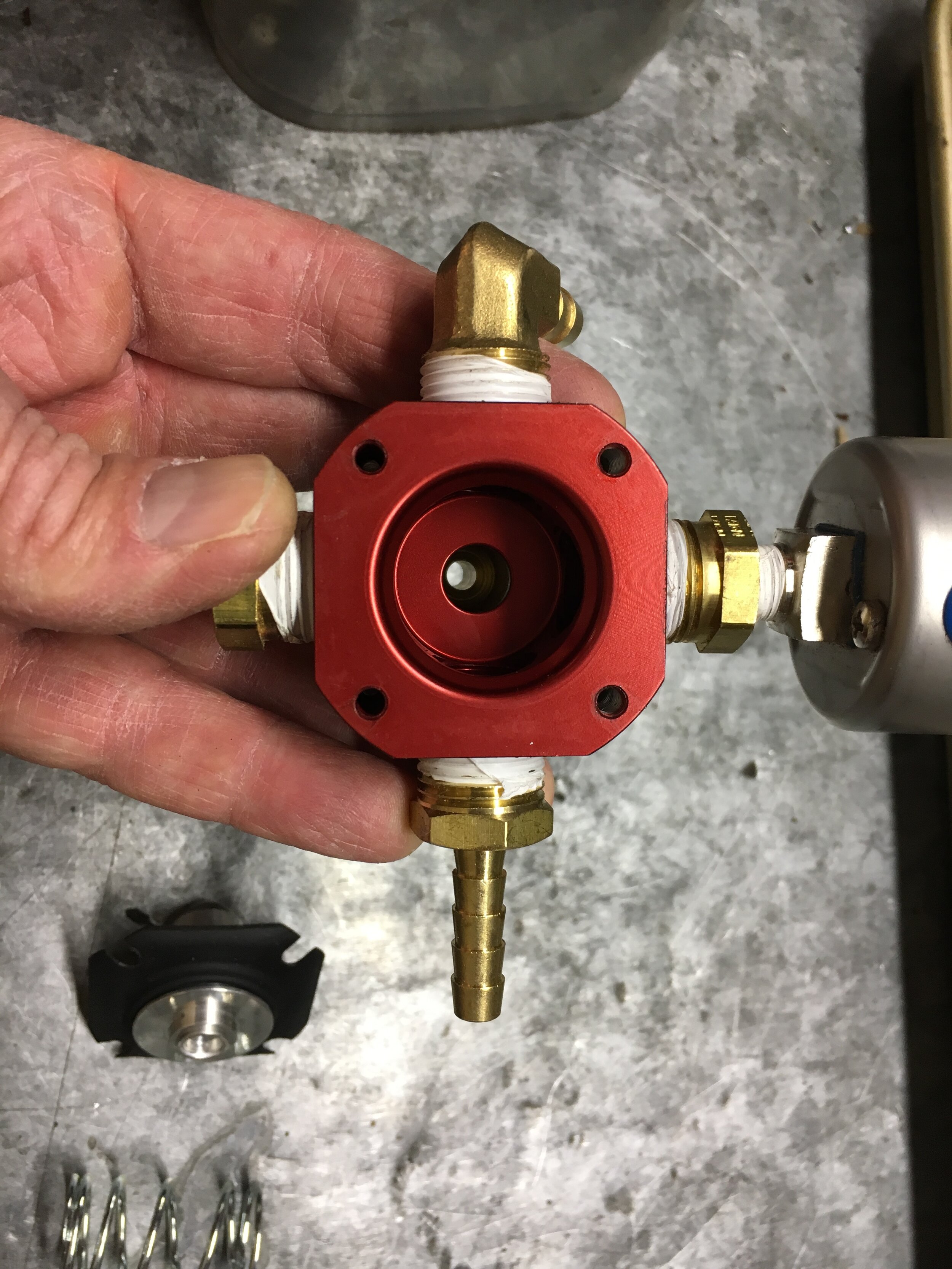
In the first below series, the images show, in order:
(i) 5/16” high-pressure delivery line (front nipple, with EFI-spec clamp) and 1/2” return line (bottom of regulator, with regular hose clamp);
(ii) 1/4” low-pressure line out to the carburetor (with EFI-spec clamp, not really necessary but they work better with smaller hoses);
(iii-iv) the vacuum/boost reference line and its origin in the carburetor float chamber vent hose; and
(v-vi) the adjustment screw and lock nut (the adjustment screw also resides atop the Metro Regulator, as seen in the above image).
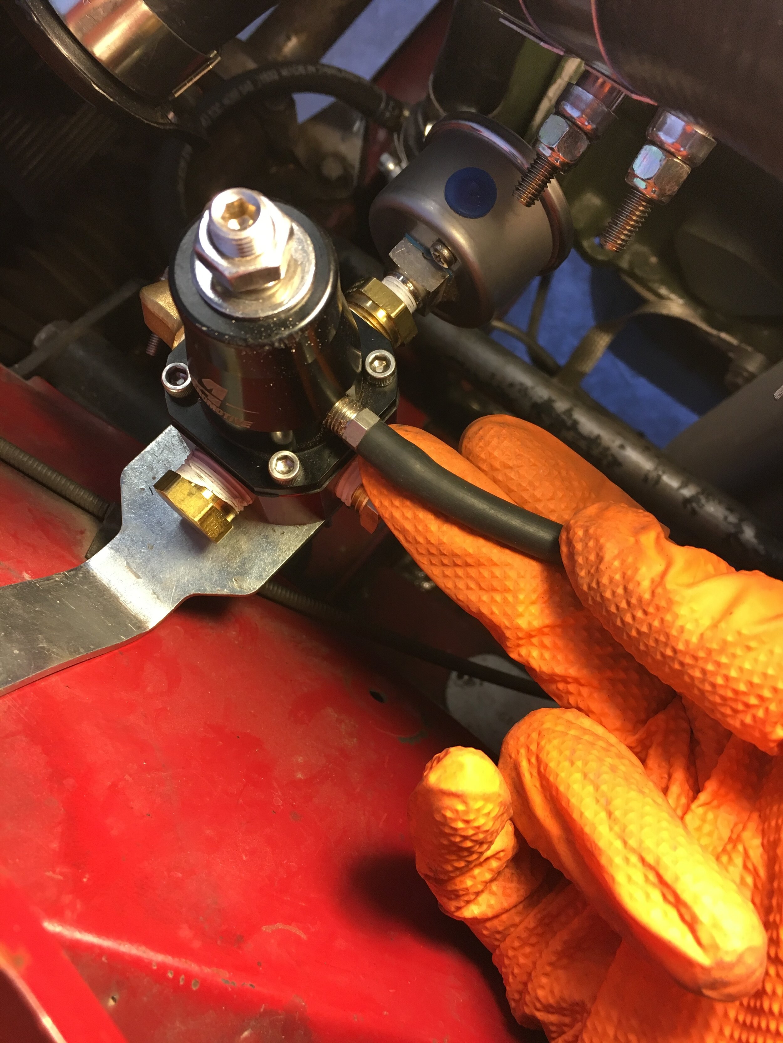

This image clarifies the vacuum hose routing for this conversion:

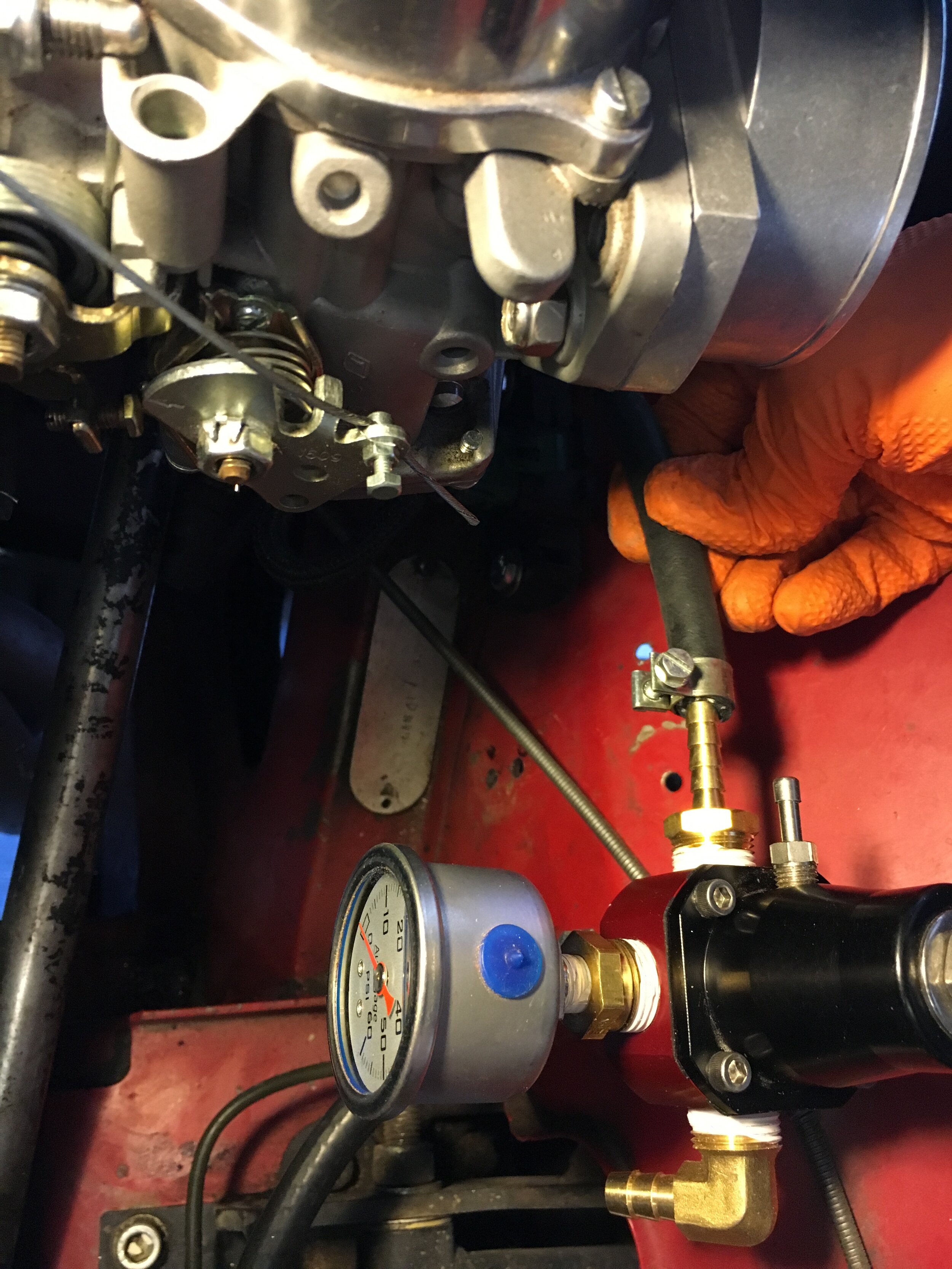
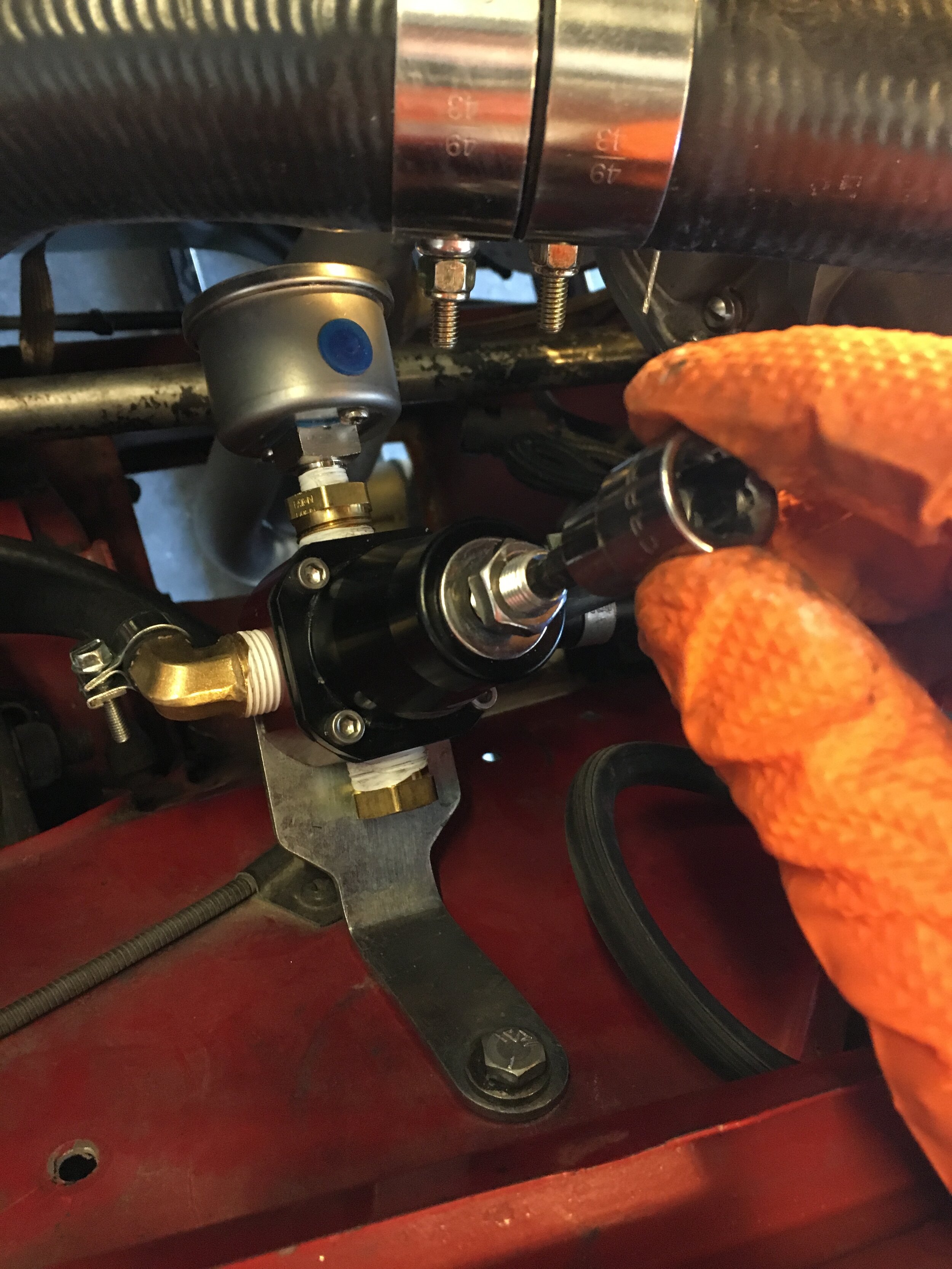
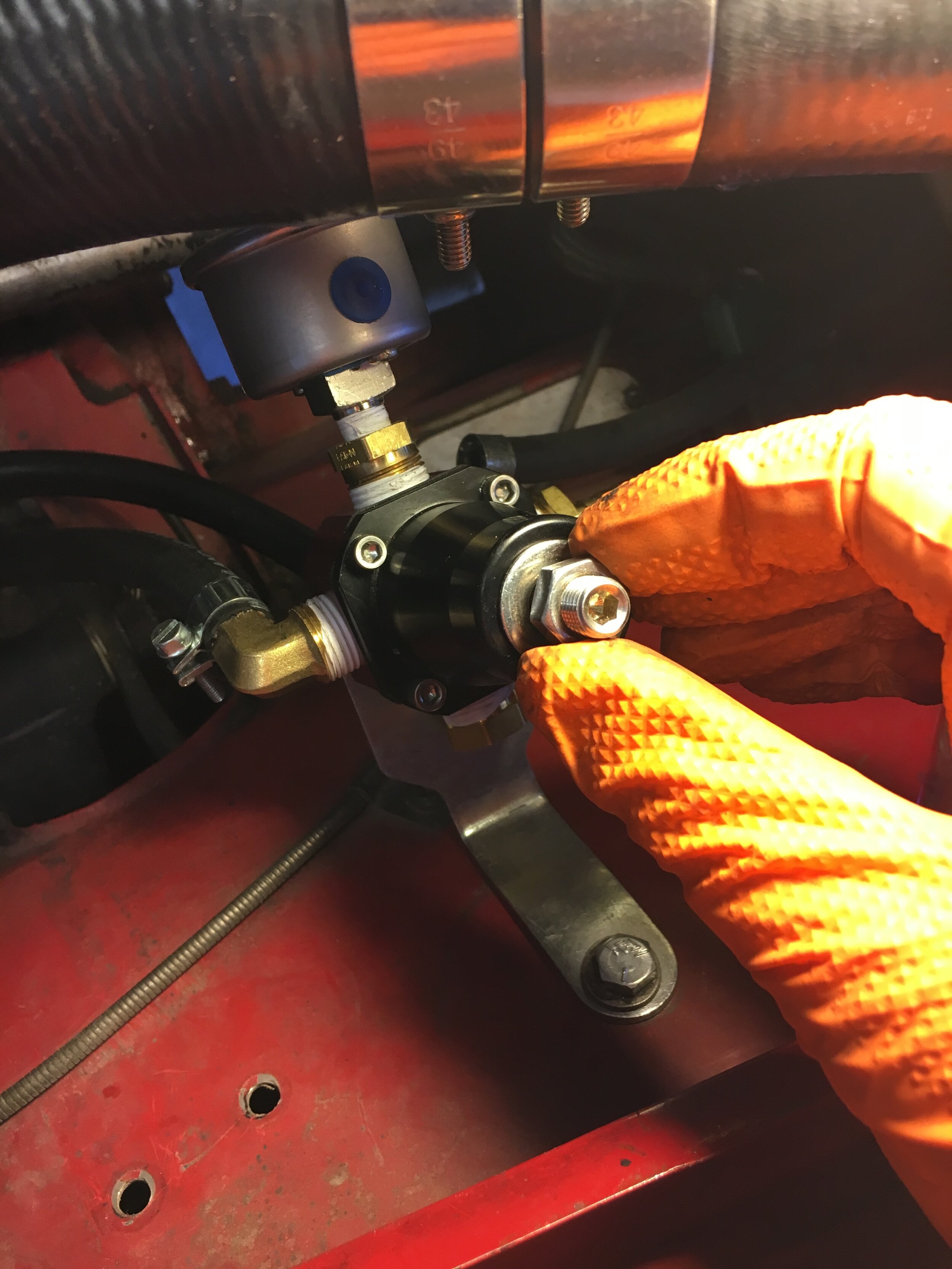
To adjust the regulator of your choice, first disable the high-pressure pump (disconnect and tape off or otherwise safely insulate one of its leads) and then ensure that the low-pressure lift pump fills the swirl tank until it overflows into the filler neck as shown in the video at the end of Step 6 above.
Next, attach a gauge with a pressure range of 1-10 psi (for greater accuracy) to the nipple that would ordinarily feed the carburetor, and enable the high-pressure pump (together with the low-pressure pump, of course—which should never have been disconnected).
Now, turn the ignition key on WITHOUT starting the engine. In this series you see an external test gauge temporarily attached to an NPT nipple threaded into one of the ports of the Aeromotive regulator and then replaced with a plug. With the Metro Turbo regulator, insert a Tee fitting into the line leading to the carburetor:
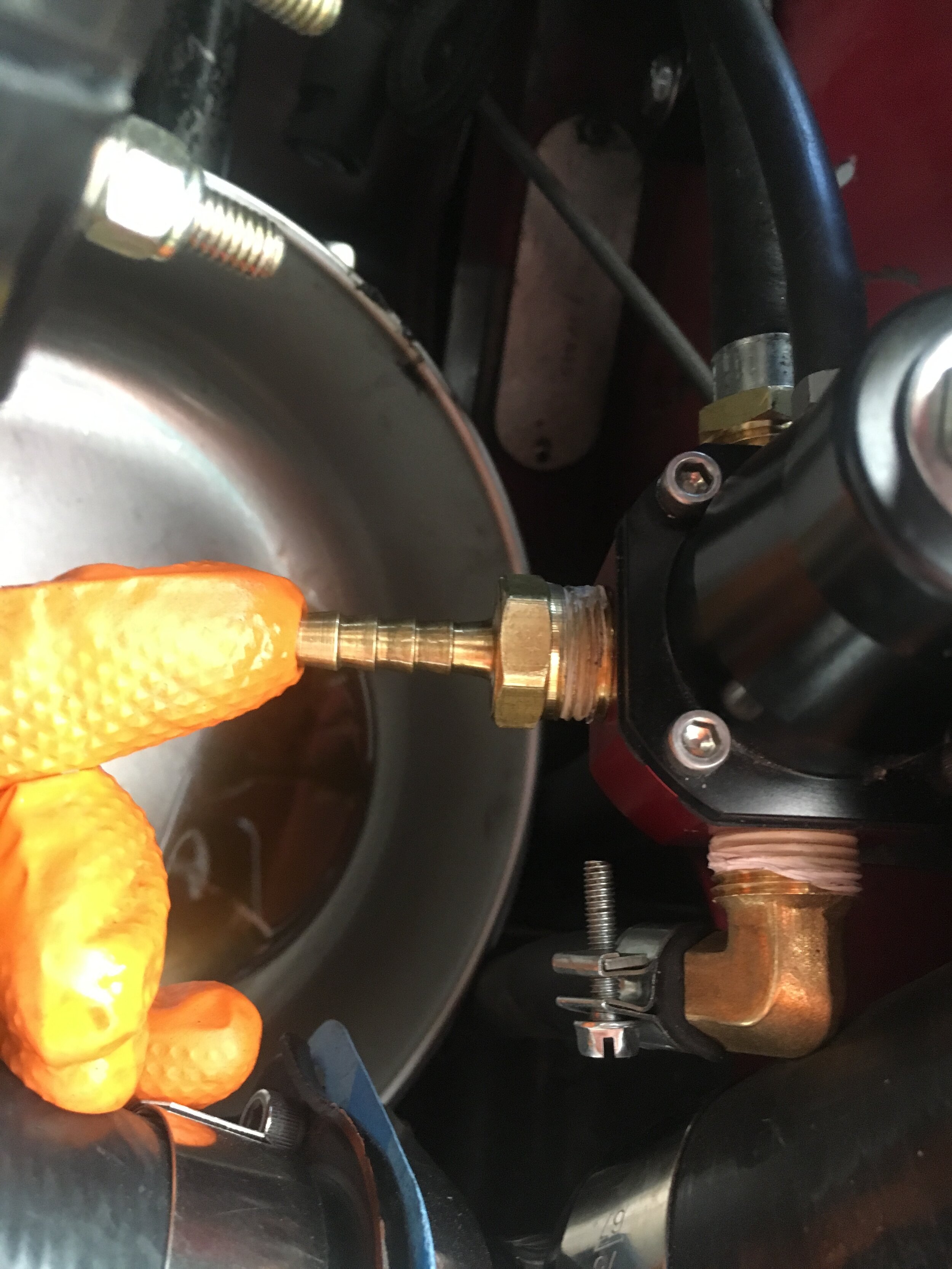
Our AN compression fitting at the end of the 1/2” return line leaked shortly after the pump was triggered because we were overcautious tightening the aluminum fittings, but a quick cinch with two wrenches immediately resolved the issue.
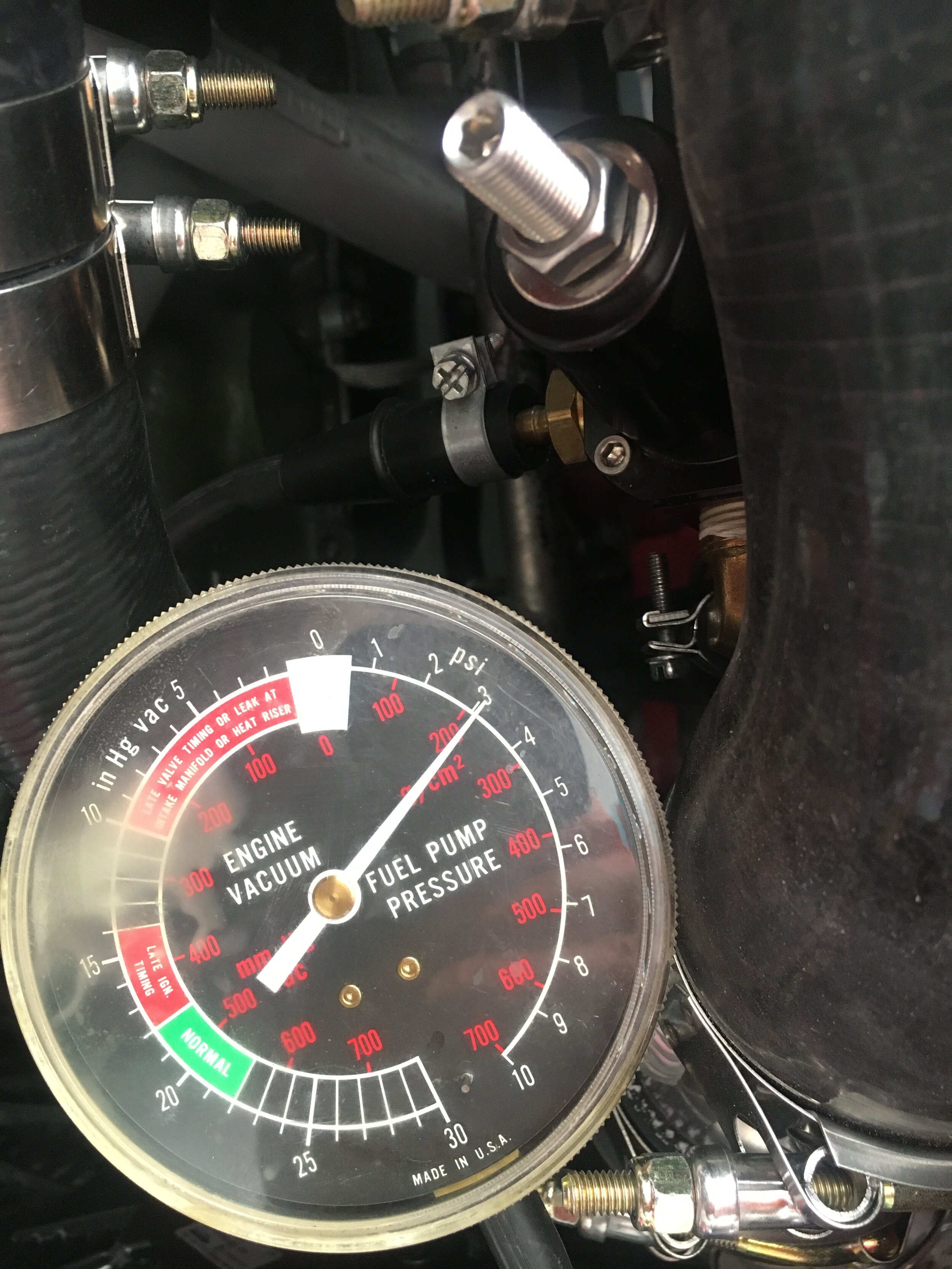
If there is no fuel pressure, turn the ignition key to the OFF position, wait a moment, return the ignition to the ON position, and recheck the fuel pressure. Repeat this OFF and ON procedure until the gauge registers pressure. (In our case, the high-pressure pump primed instantly due to the full swirl tank, and it took just seconds to charge the delivery line and register pressure on the gauge.)
Once pressure registers on the gauge, turn the adjustment screw counterclockwise to decrease the pressure, and clockwise to increase it. Your goal is to set a base or initial fuel pressure of 3 psi with the engine off, or before the regulator’s rising rate vacuum function kicks in:

Leave the pumps on for a few seconds to make sure the pressure setting does not vary, and walk to the rear of the car and remove the filler cap to listen for fuel circulating out of the overflow and down into the main tank—which you can see with a flashlight and mirror as shown in the video at the end of Step 6.
Recheck all fittings for leaks, turn off the key, and reconnect your Pertronix module if you are running one.
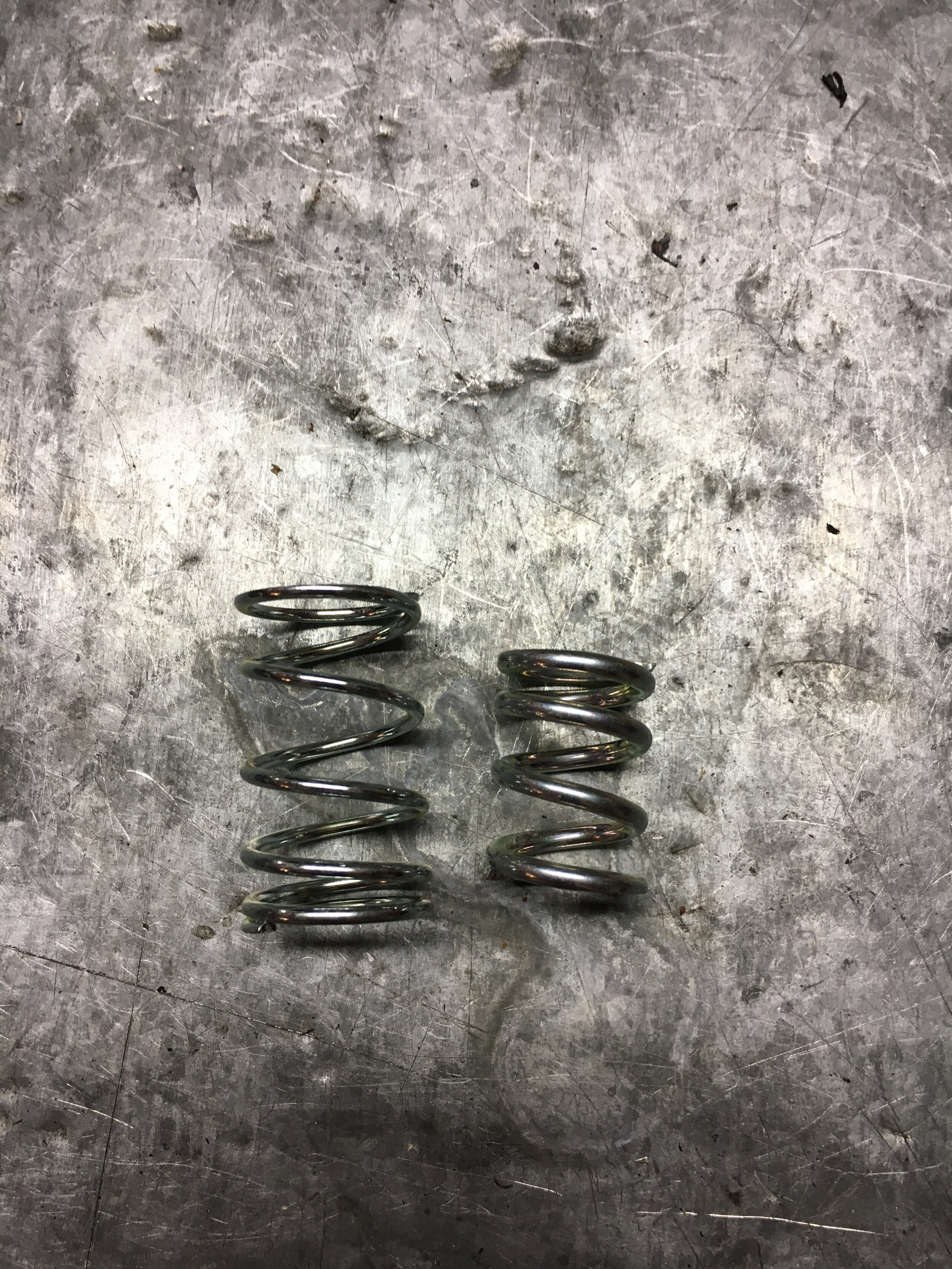
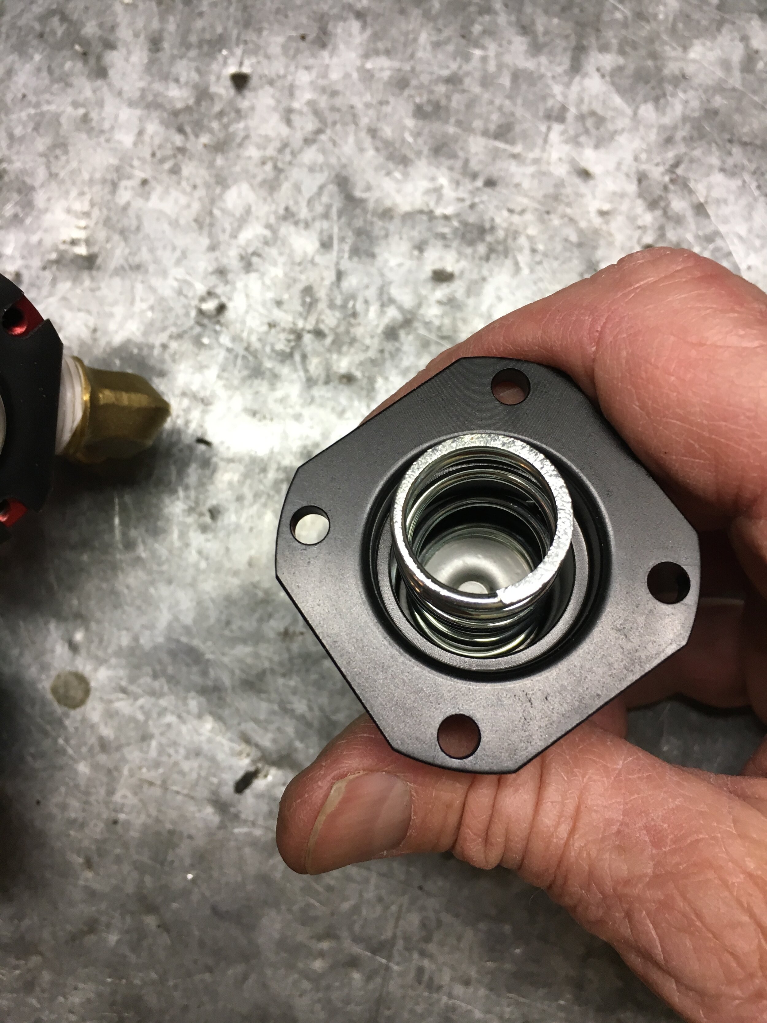
Finally, although you may find the instructions adequate, here is a slide show illustrating how to make sure you have the low-pressure spring installed if you opted for a universal-style regulator like the Aeromotive model we used in anticipation of running EFI later on.
The high-pressure spring is the shorter, stiffer one. The last image indicates the rising rate vacuum nipple, which is connected to the same vacuum circuit that feeds the 2002 Mini Cooper S supercharger bypass valve and the boost gauge (if you have mounted one in the passenger compartment):
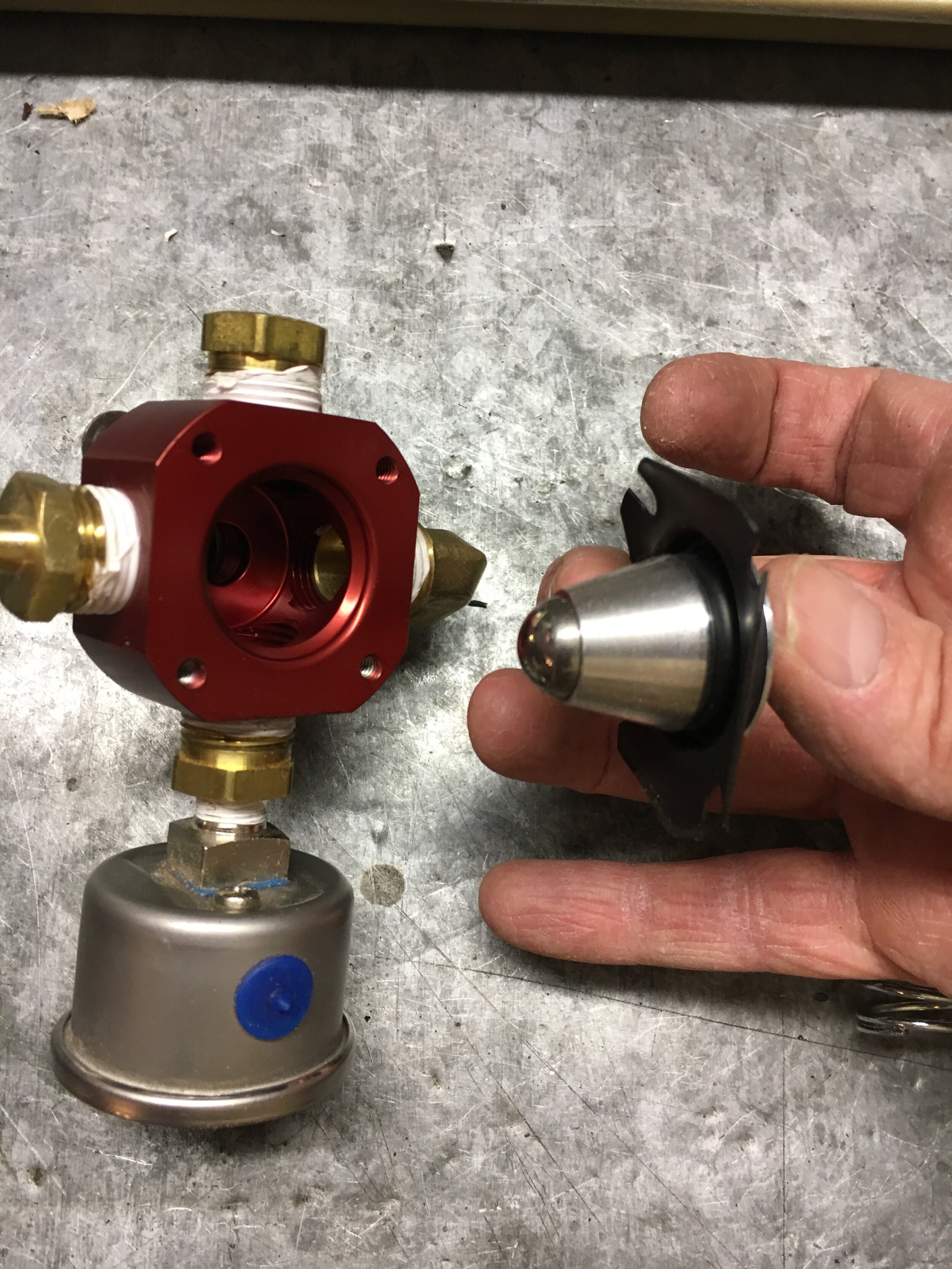
Note in the above slideshow that the integral pressure gauge is designed for an EFI system, and is probably not accurate enough to set the base pressure for this system, which is 3 psi maximum.
If you intend to run a carburetor indefinitely, you may either buy a gauge with a lower range, or temporarily install a nipple to attach a regular pressure test gauge in order to set the base pressure, before ultimately installing an NPT plug.
wire the high pressure fuel pump
The existing low-pressure pump wiring includes a bullet connector, used widely throughout the OEM Spridget wiring. While generally acceptable, such connectors increase resistance and because the author wanted to try running both pumps using the single existing lead, the bullet connector was replaced by a soldered and shrink-wrapped splice connection:

Note that the grommet used to wire the high-pressure pump in the above photo was installed by the factory, and is located by lifting the carpeting in the boot:

The Walbro pump is fairly noisy, and the OEM cardboard divider between the boot and passenger compartment almost useless in reducing the din. The author intends to add a thin piece of plywood and/or a layer of insulation or two to quiet things down—though the pump may not be an issue with a supercharged A-series wailing in your ears.
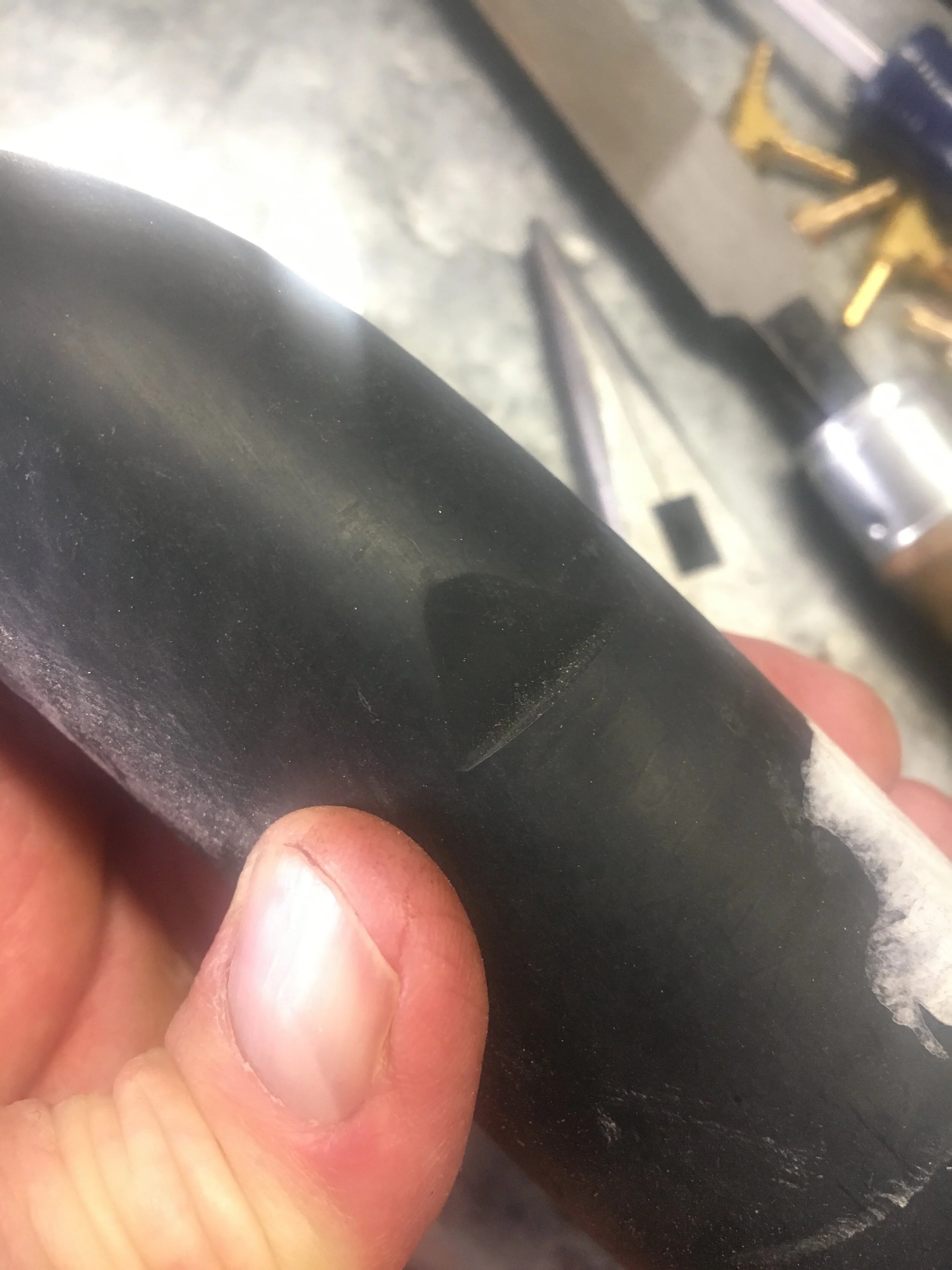
replace the supercharger pulley
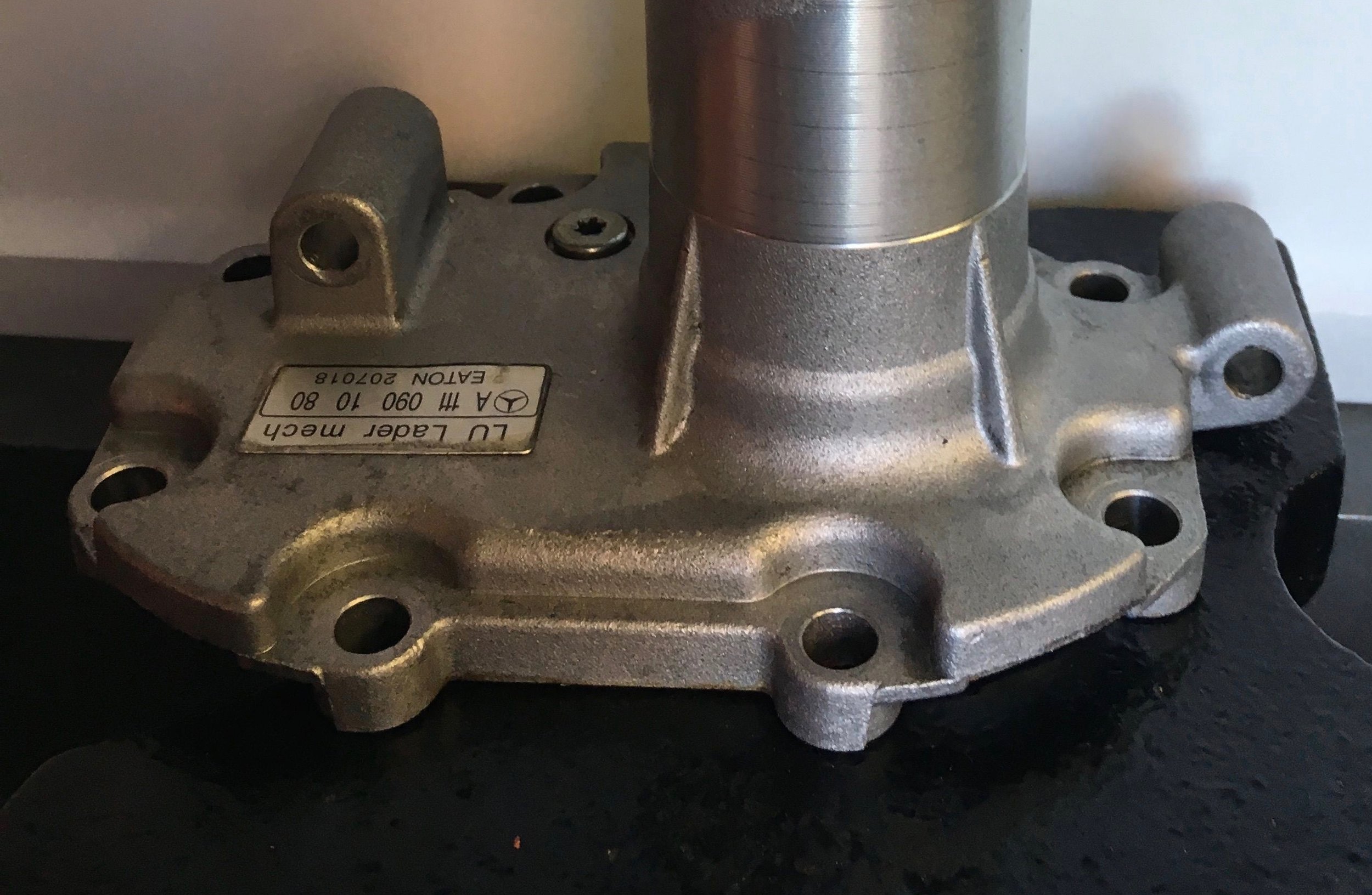
The M45 mounted to the Mercedes donor car is fitted with a pulley made of pressed steel welded to a hub, and must be removed and replaced with the Smoothflow M45 Modular Pulley System.
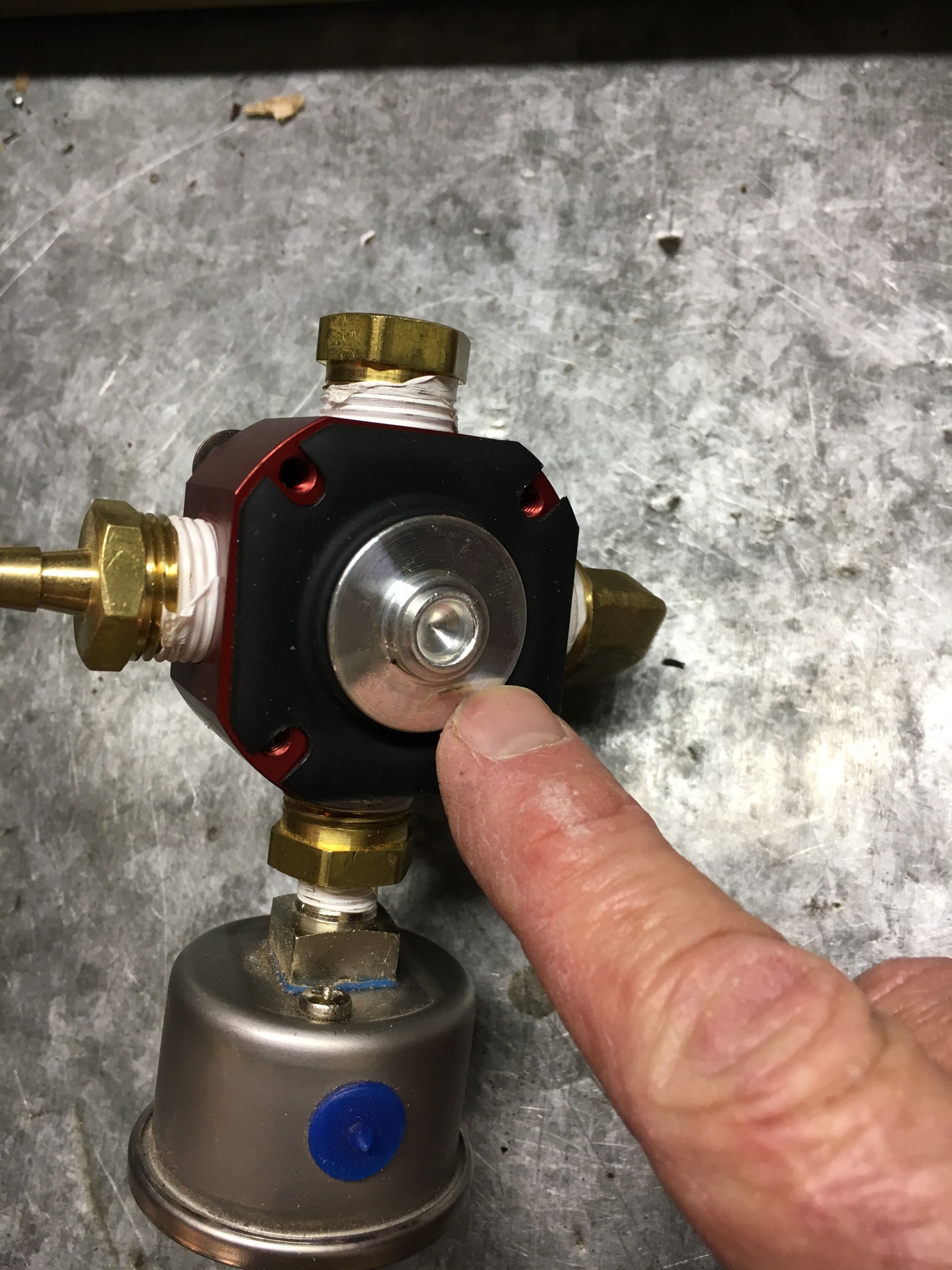
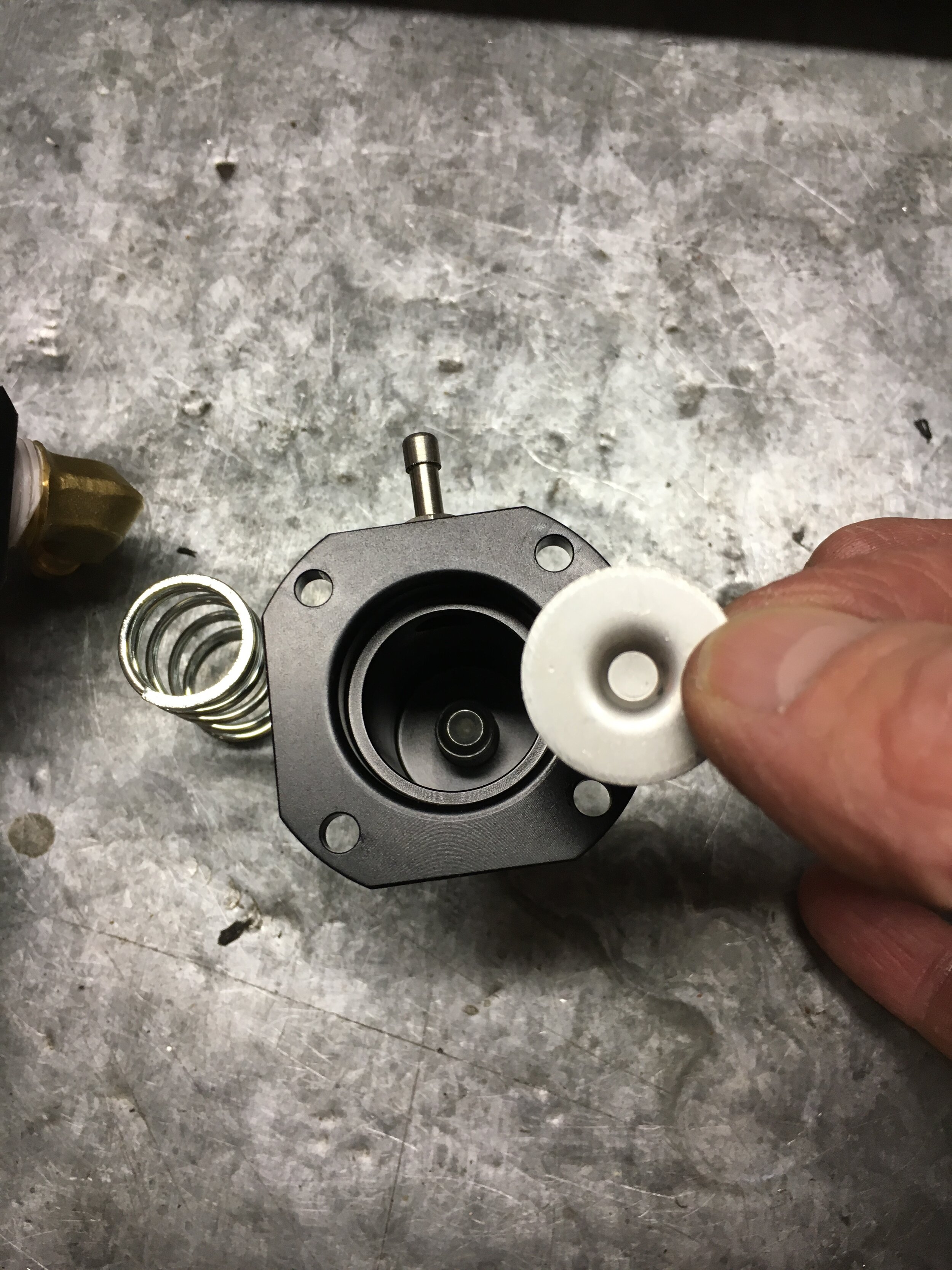
The first step is to remove the plastic cap covering the threaded hole in the drive shaft. It is pressed into place but will come out easily by turning it anti-clockwise with a pair of pliers:

Before you go any further, apply liberal amount of penetrating oil to the shaft and let it soak into the joint.
There are three methods of removing the pulley—and make sure you protect your eyes and face regardless of which you use.
First - at least one Spridget owner has successfully used a standard two-jaw pulley remover, as shown here:

If you attempt the above method, you will need quite long wrenches to achieve sufficient torque.
Second, you can use an arbor press if you have access to one. A standard bearing removal tool may be used to grab the pulley’s skirt—which will not survive:

If using an arbor press, do not forget to place a box of rags or your hand underneath to catch the snout housing when it comes loose.
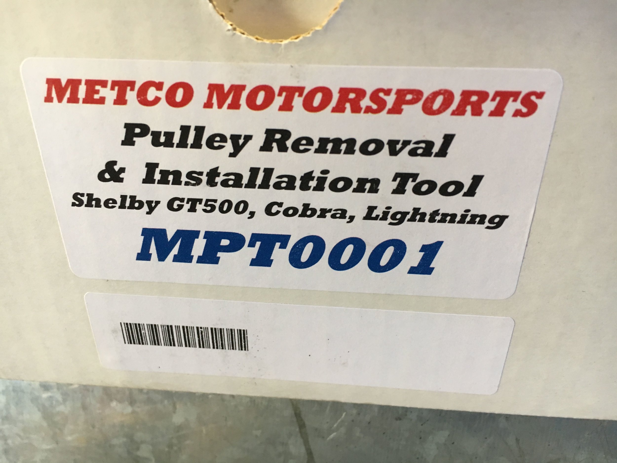
A third method is using a dedicated supercharger pulley removal tool. Various companies offer these pullers for sale.
We prefer the Metco Motorsports puller pictured below, and will rent the tool to purchasers of our M45 supercharger manifold for the cost of outbound shipping with a refundable damage deposit (you are responsible for return shipping as well), by clicking here.
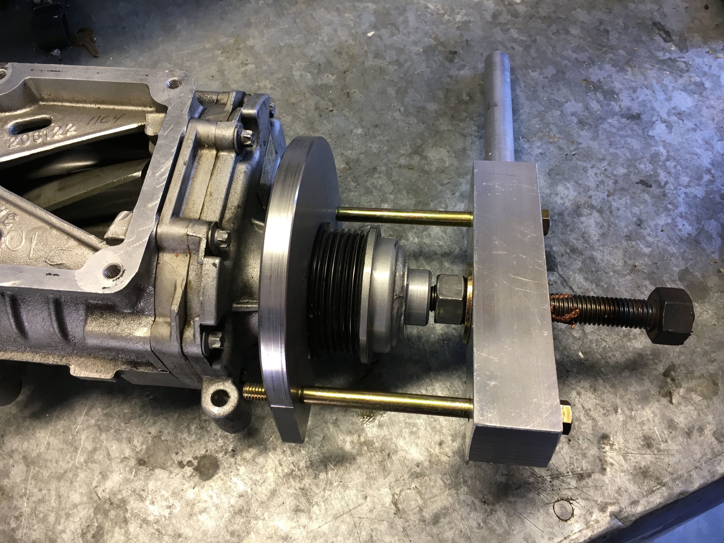
It is also advisable to use a high-quality lubricant on the threads and tip where the tool contacts the supercharger shaft (we include a quantity of ARP fastener lubricant with the puller rental) to maximize the tool’s efficiency and reduce wear.
Use a 1/2” drive breaker bar and socket on the central bolt, and a piece of heavy pipe or other suitable cheater bar to hold the tool’s handle.
To install the Smoothflow M45 Modular Pulley System’s steel hub, you may use the special tool or an arbor press if you have one. The only benefit of using the special tool is that you can complete the procedure without opening the supercharger’s gear case. (This is not a concern, as it is easy to reseal it with Permatex anaerobic sealant. Rotor timing is not required to open the gear case.)
The following photo series shows how to use a standard arbor press to install the pulley. Be sure to lubricate the shaft before pressing on the hub.
The third image emphasizes that you must fully support the supercharger’s aluminum snout assembly during the pressing operation to avoid shattering it.

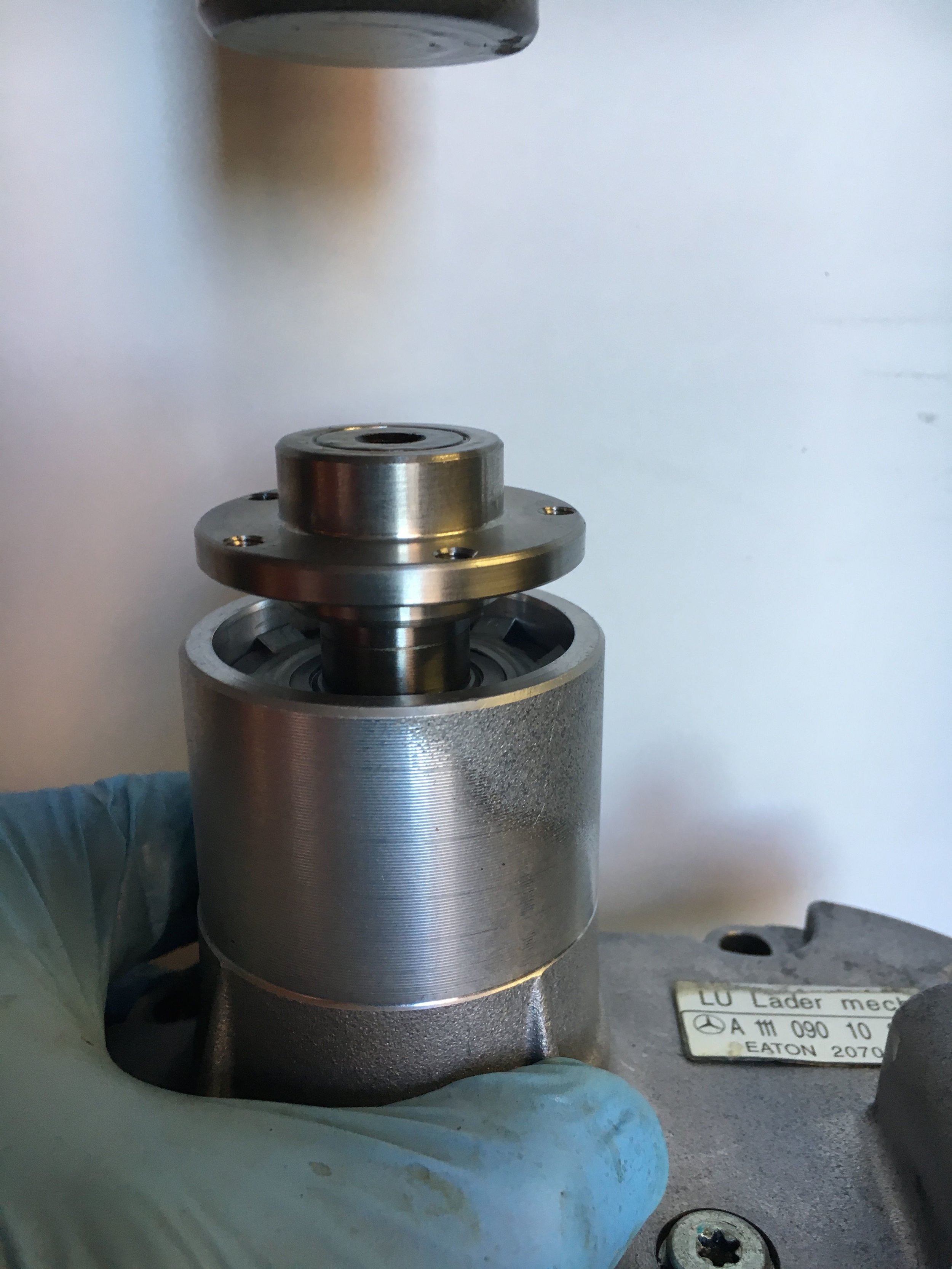
Be sure to press the hub just until it is flush with the end of the shaft.
prepare the supercharger
Assuming you have purchased a new supercharger or located a viable used supercharger (see ‘select a supercharger’ farther down on this page), there is little to do other than swapping the pulley (previous section) and changing the synthetic oil in the gear box (explained in a moment).
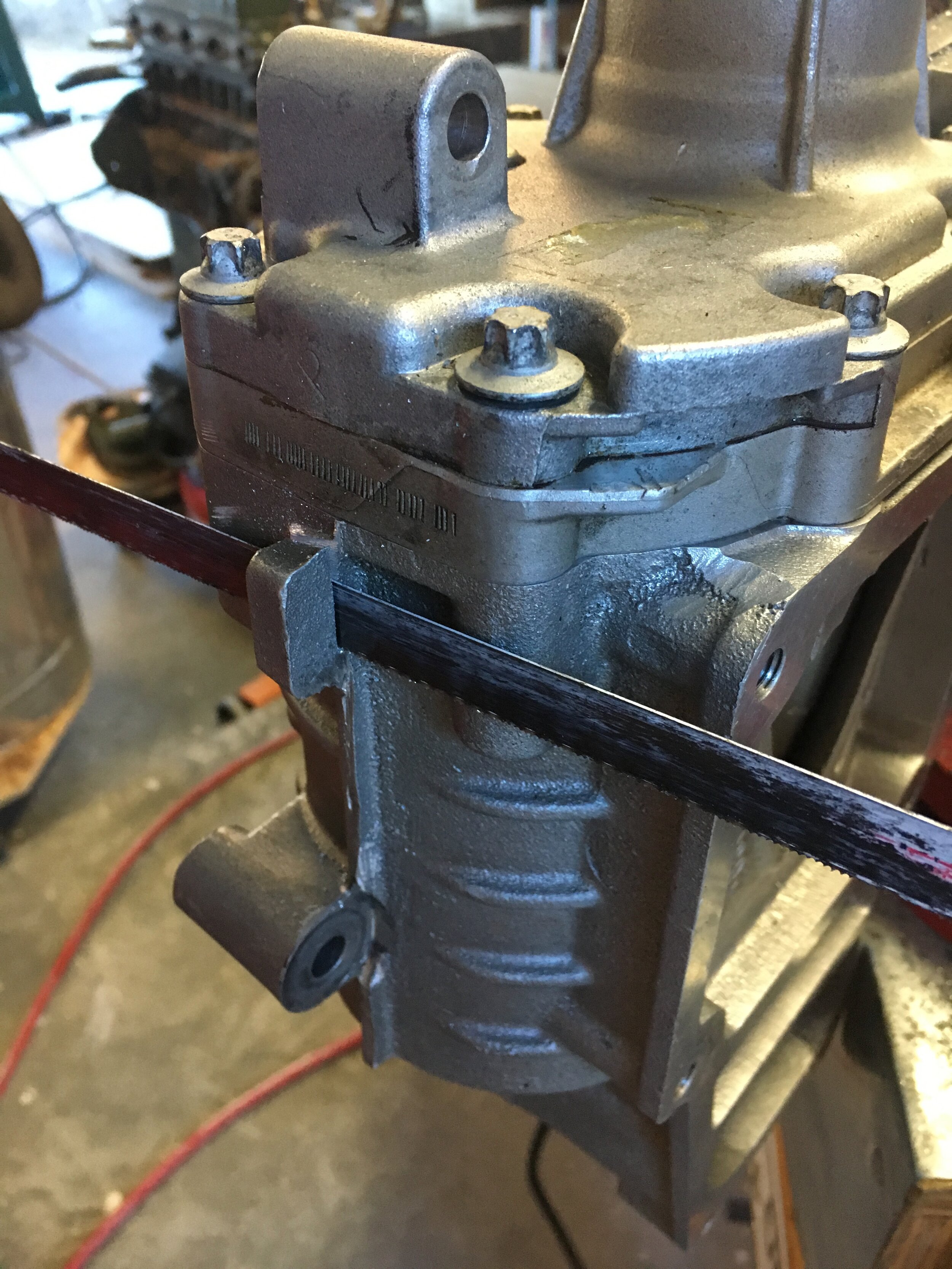
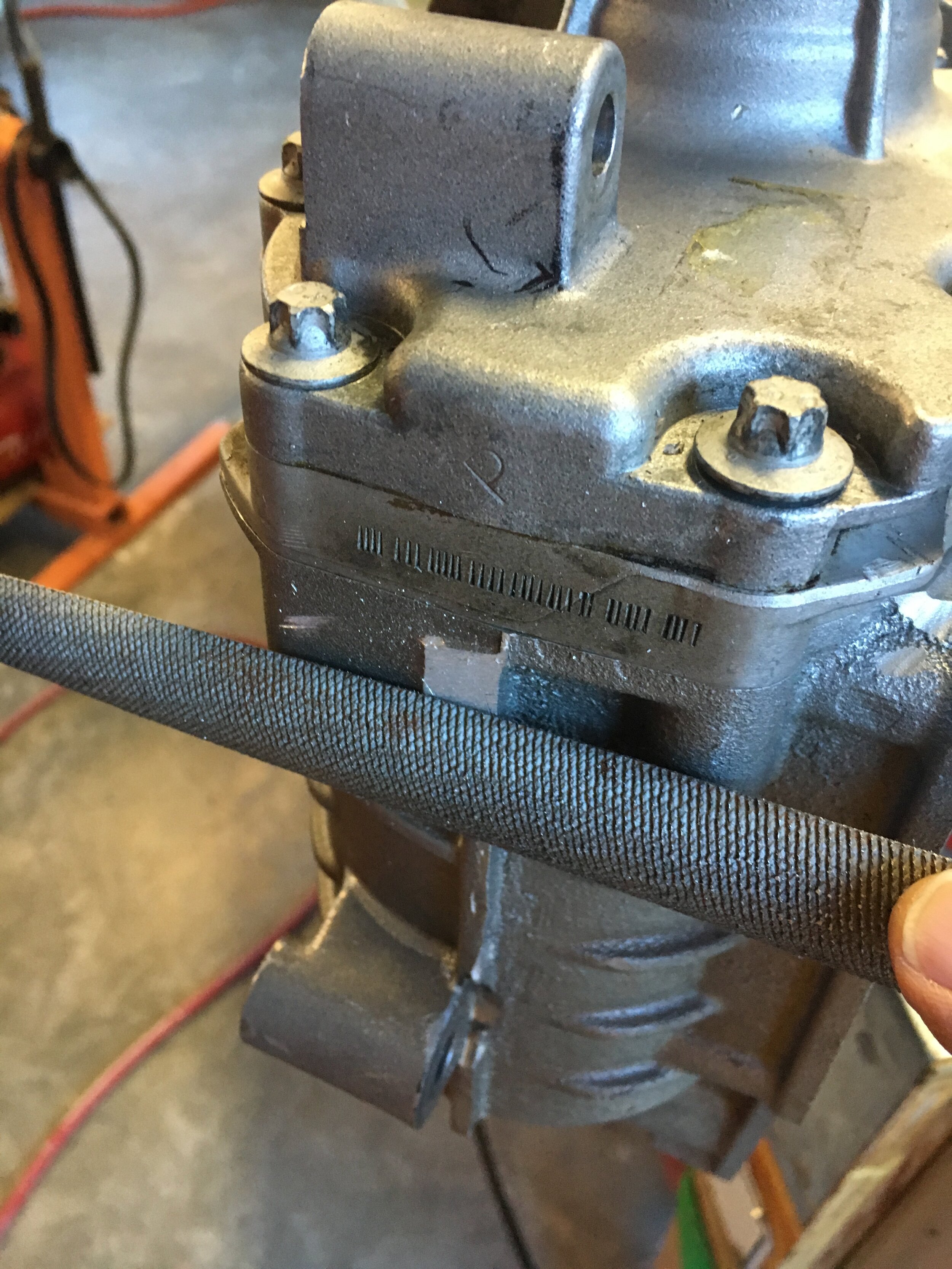
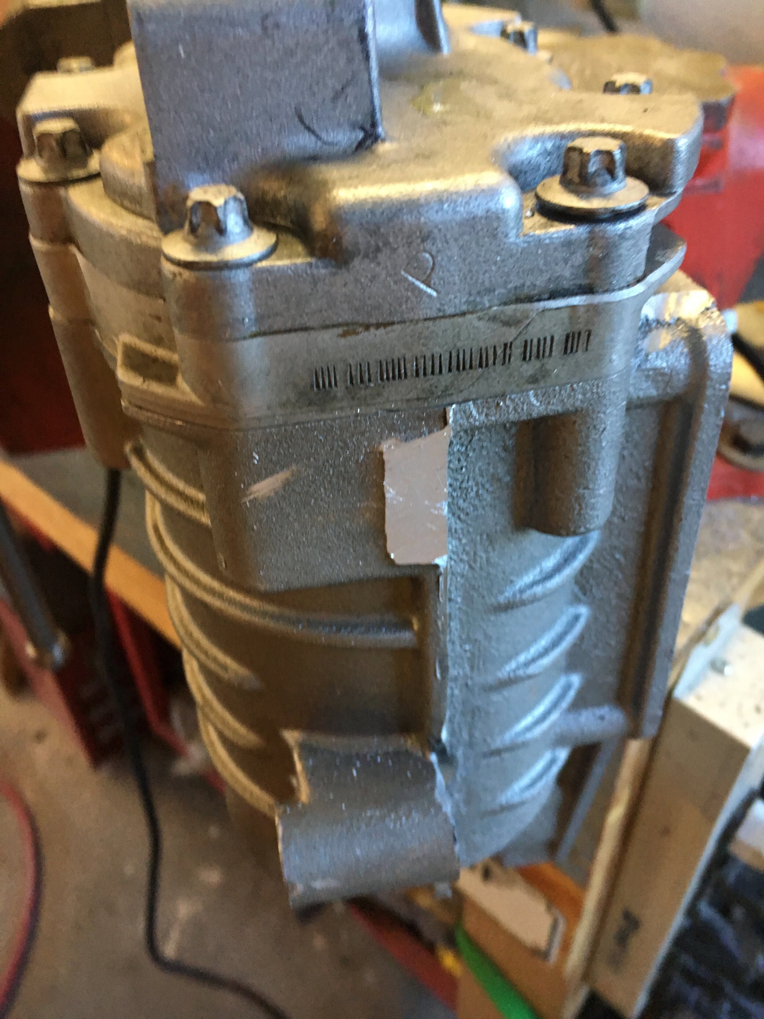
However, in some installations, variations in fabricating the mounts or a larger alternator diameter may cause the tab on the inboard side to contact the alternator’s case. This is no cause for alarm and is easily rectified by removing the tab, which in no way weakens the rotor chamber:
Changing the gear box oil is simple, and in our estimation should be done frequently. Mercedes essentially proposes never changing the oil, but our examination of blowers with 100,000 miles and above suggests this is because Mercedes treats the units as expendable.
For comparison, here is the oil drained from a supercharger with just 10,000 miles on the car’s odometer when it was totaled, next to a bottle of fresh synthetic fluid—GM part no. 12345982:

We recommend changing the oil every 15,000 miles, or every two years—which every comes first. You can do it more frequently if you do not mind spending the hour and $8.00 required to do so. You should add 3.5 to 4.0 fluid ounces.
First, release the serpentine belt, unfasten the snorkel clamps at the supercharger’s inlet and outlet, and remove the four allen screws attaching the unit to the mounts.
Next, remove the drain plug—but as soon as it breaks loose, place a rag over the plug and torx bit to protect your eyes from the possible expulsion of atomized supercharger oil due to pressure build-up inside the gear box.
Make sure you have a receptacle positioned under the unit to catch the old fluid, and fully unscrew the plug, taking care to examine the O-ring, which should probably be replaced as a matter of course:

You should tilt the unit alternately toward its rear and front to allow oil to drain past the caged ball bearings in the snout into the gear box and out through the drain hole.
Next, pour in the fresh oil, replace the O-ring on the drain plug, and tighten sufficiently to seal the plug. Take care not to over tighten the plug and damage the O-ring or strip out the aluminum housing.
Finally, reinstall the supercharger, align the pulley as discussed elsewhere in these instructions, and replace the serpentine belt.
Install the M45 manifold
Once you have installed the modular pulley system, it is time to install the Creative Spridgets M45 manifold.
This is straightforward as shown in the following photo series.
Simply clean the supercharger’s mating surface carefully (a light scuffing with a red Scotch Brite pad works fine), clean the M45 manifold with Simple Green or your favorite solvent, and place and align the OEM Mercedes gasket (it can only go one way). Do not use gasket sealant.
Finally, carefully install the Allen screws, torquing to 21 Newton Meters, or 185 in. lbs. (roughly 15 ft. lbs.) per the instructions:
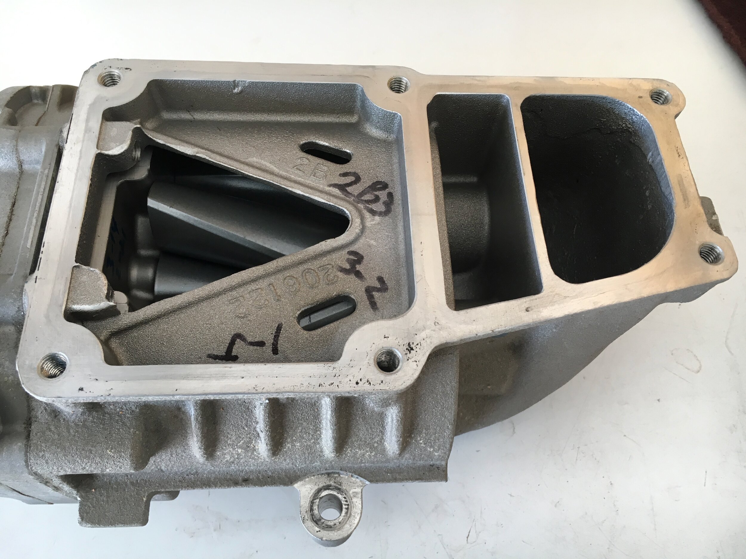
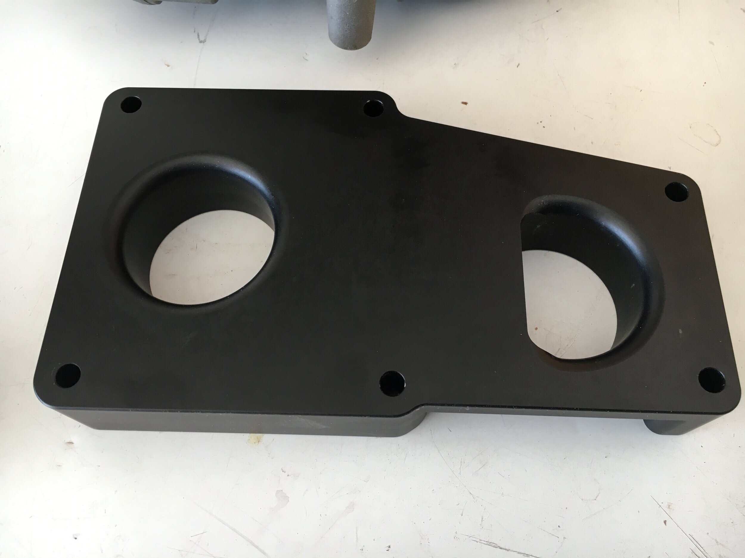
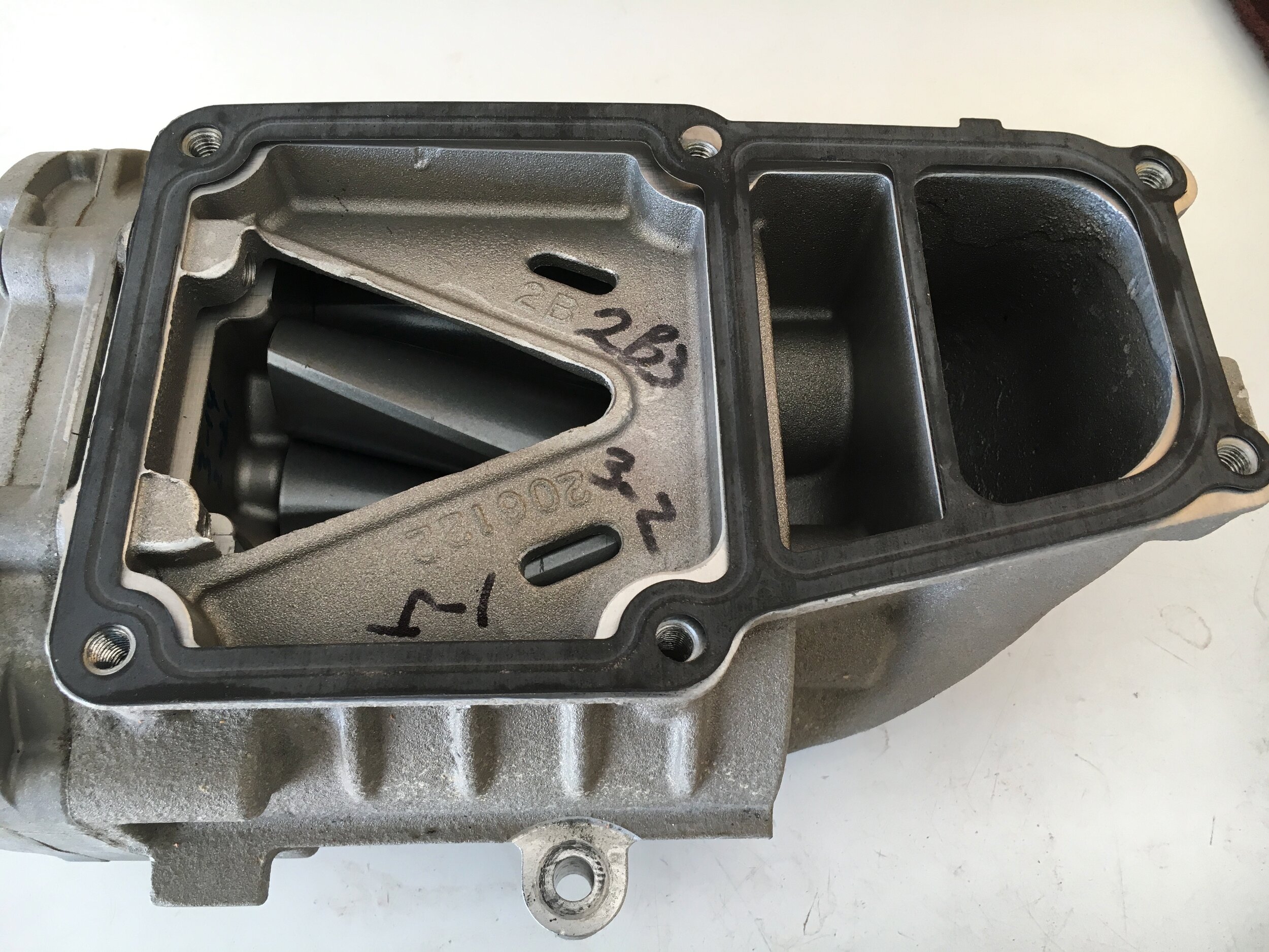
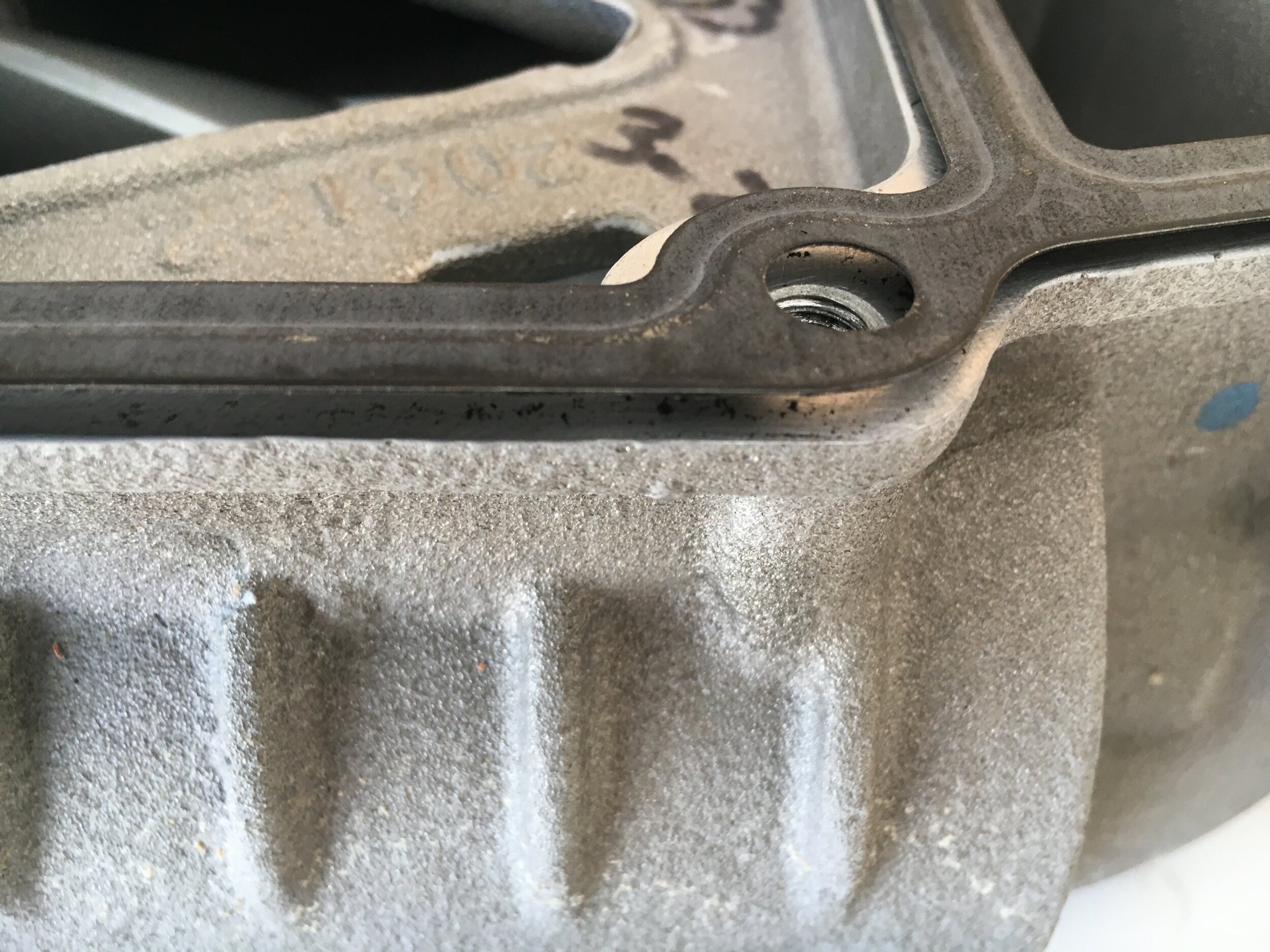
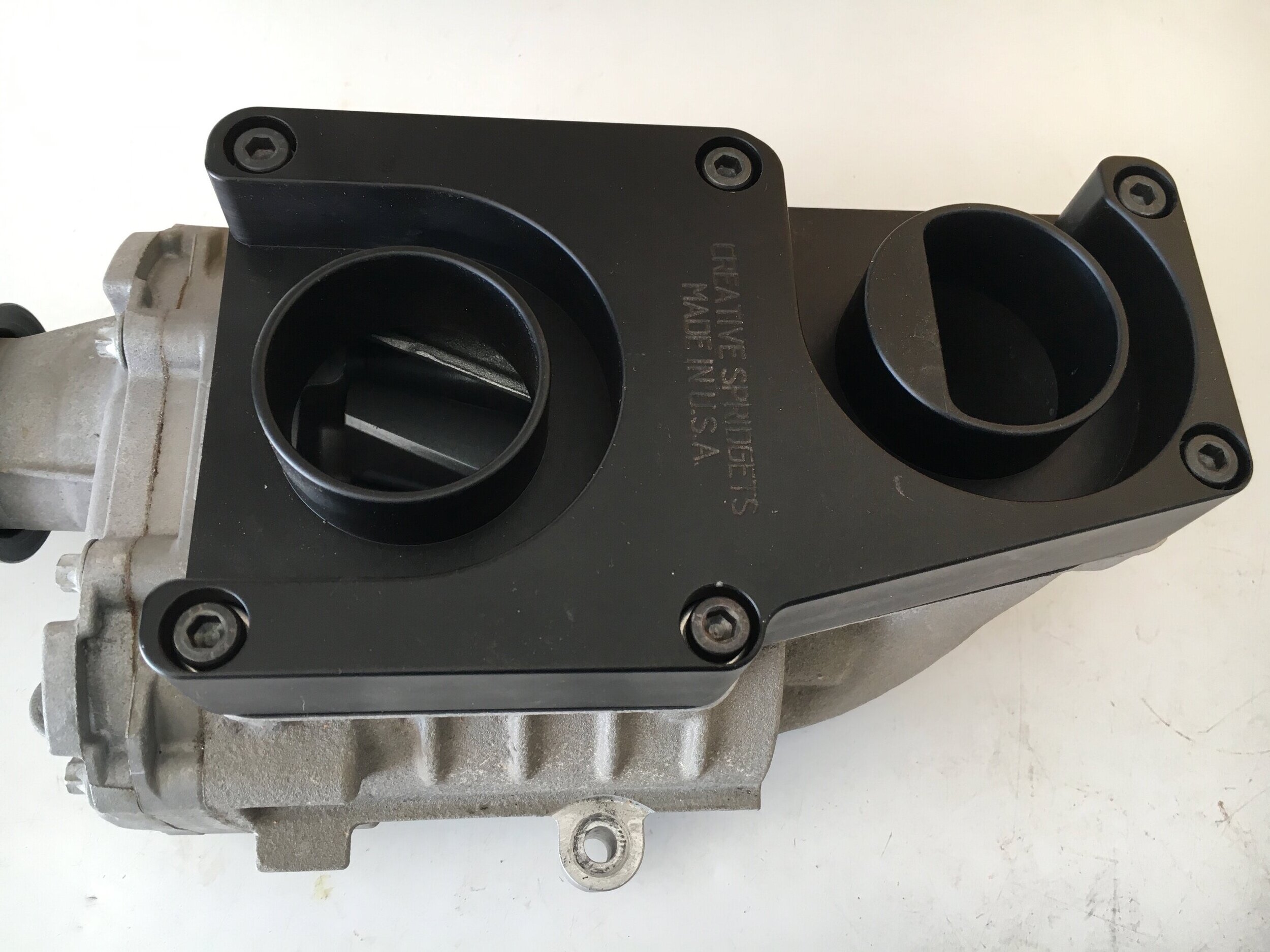
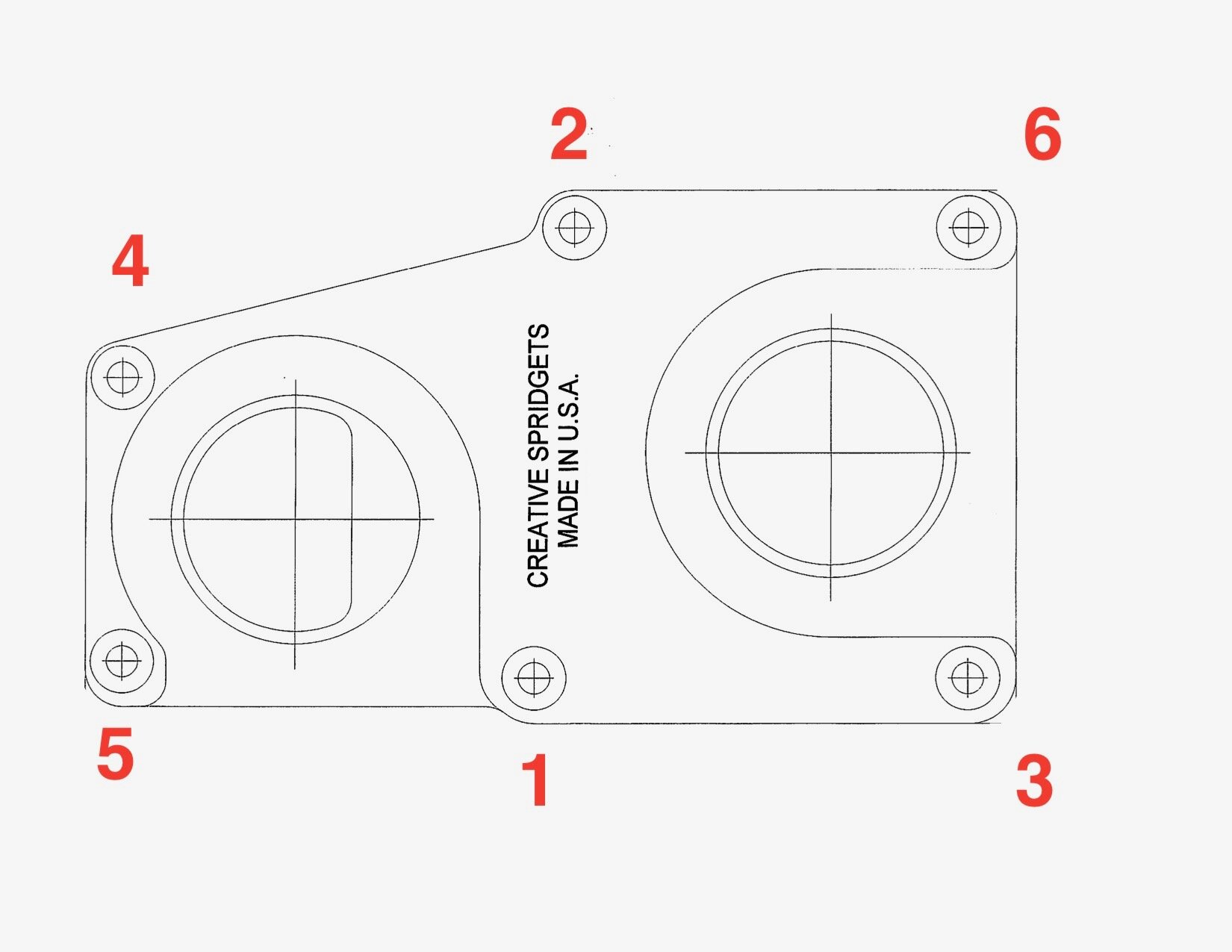
To keep things clean while installing the blower, you may wish to use painter’s masking tape or flexible PVC caps. If you use the caps, you can test the gasket sealing by pressing on first one cap and then the other:
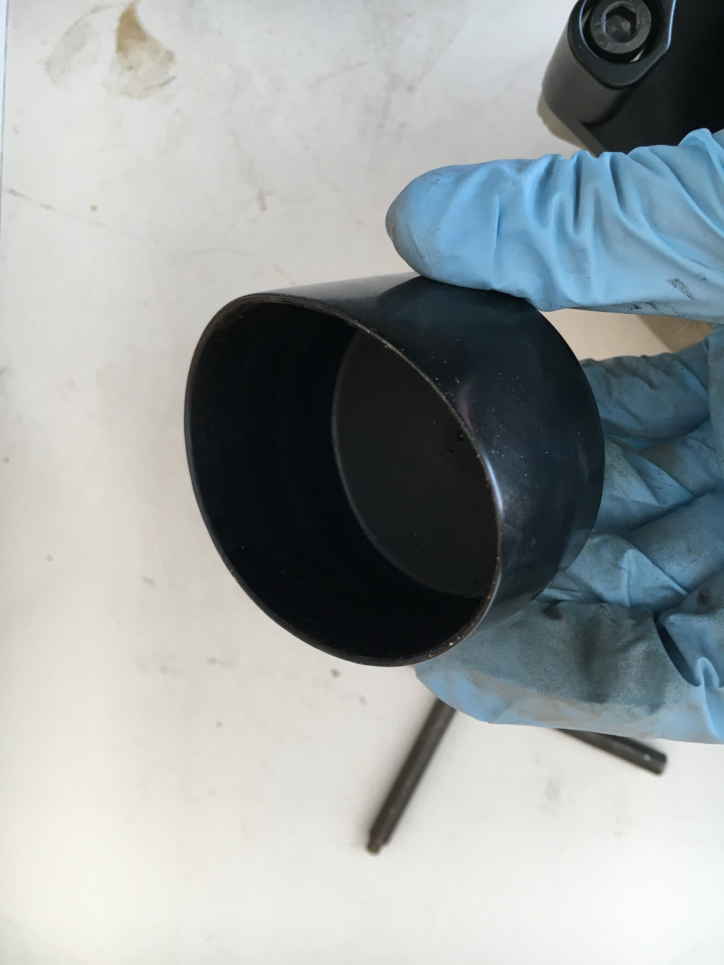
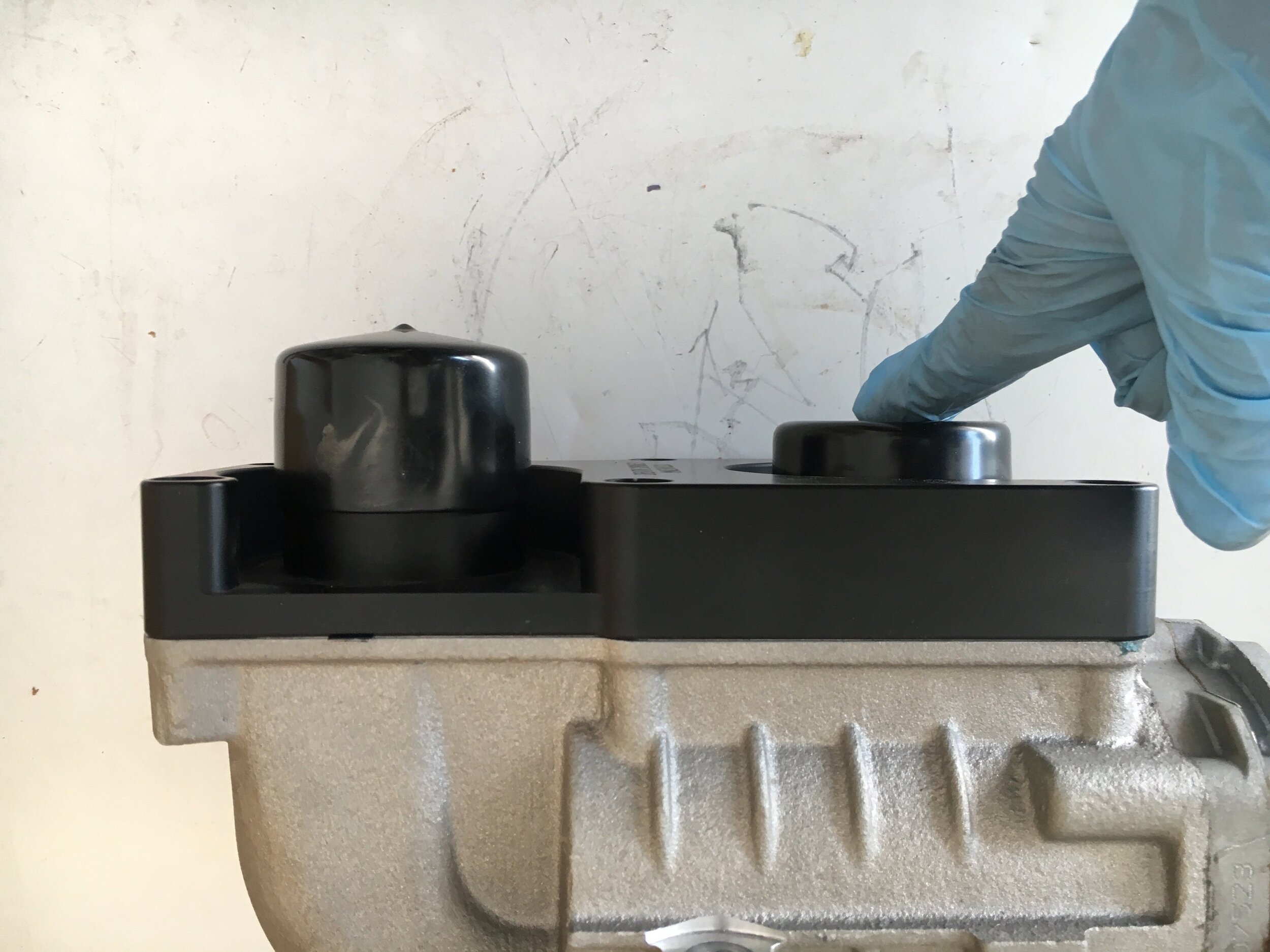
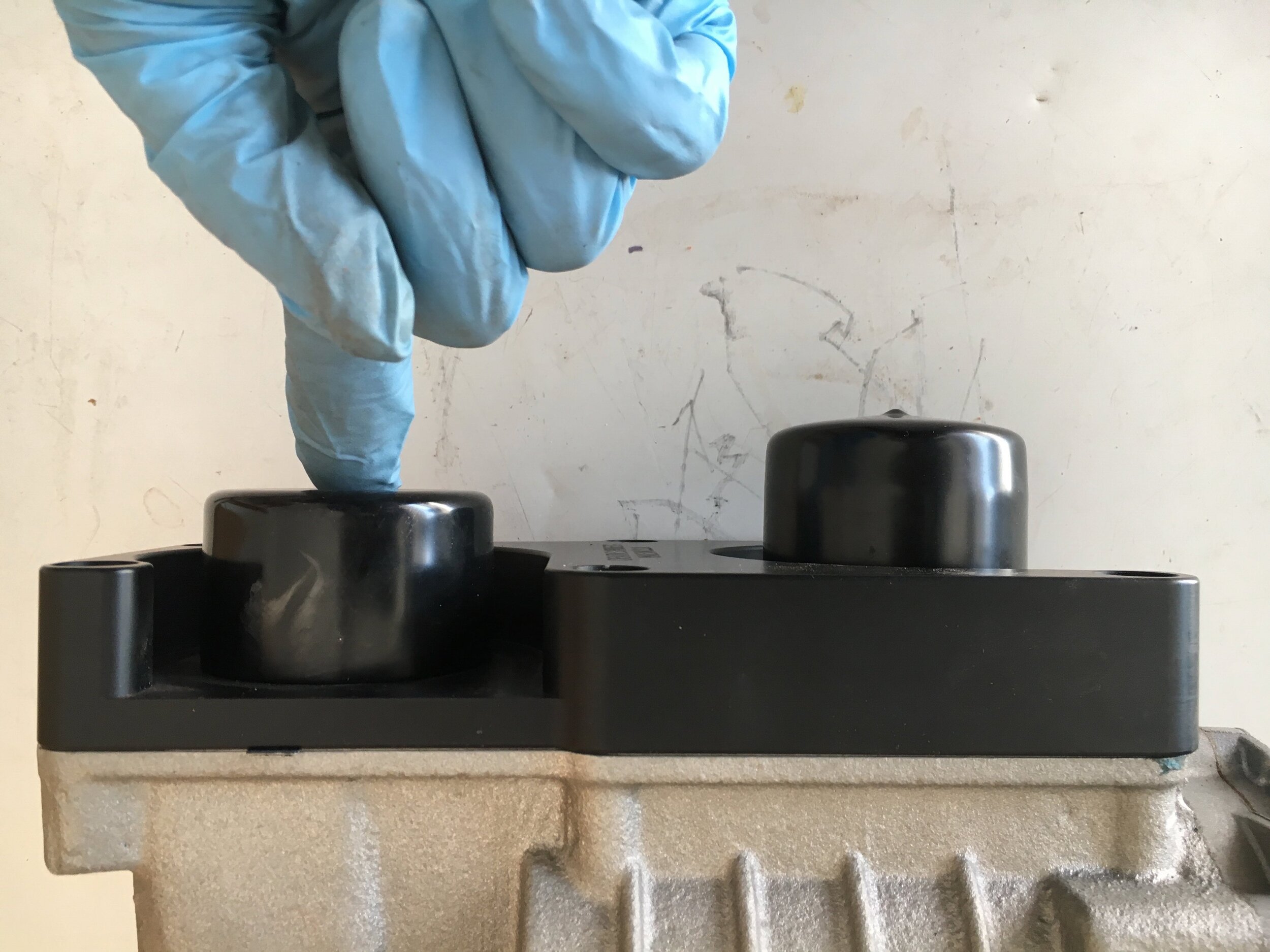
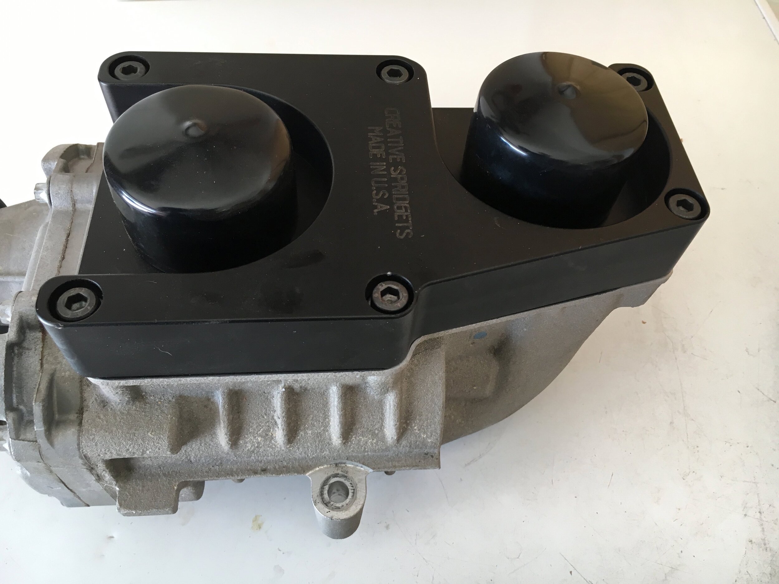
install the supercharger & align the pulley
Once you have fitted the supercharger mounts as described above, installing the supercharger and aligning the pulley are straightforward.
First, simply set the supercharger in place and slip the top/outer two Allen screws (or whatever fasteners you prefer) through the blower’s cast mounting tabs and through the ears in the mounts.
Second, install the inner/lower screws or bolts—but leave them finger-tight in order to align the pulley.
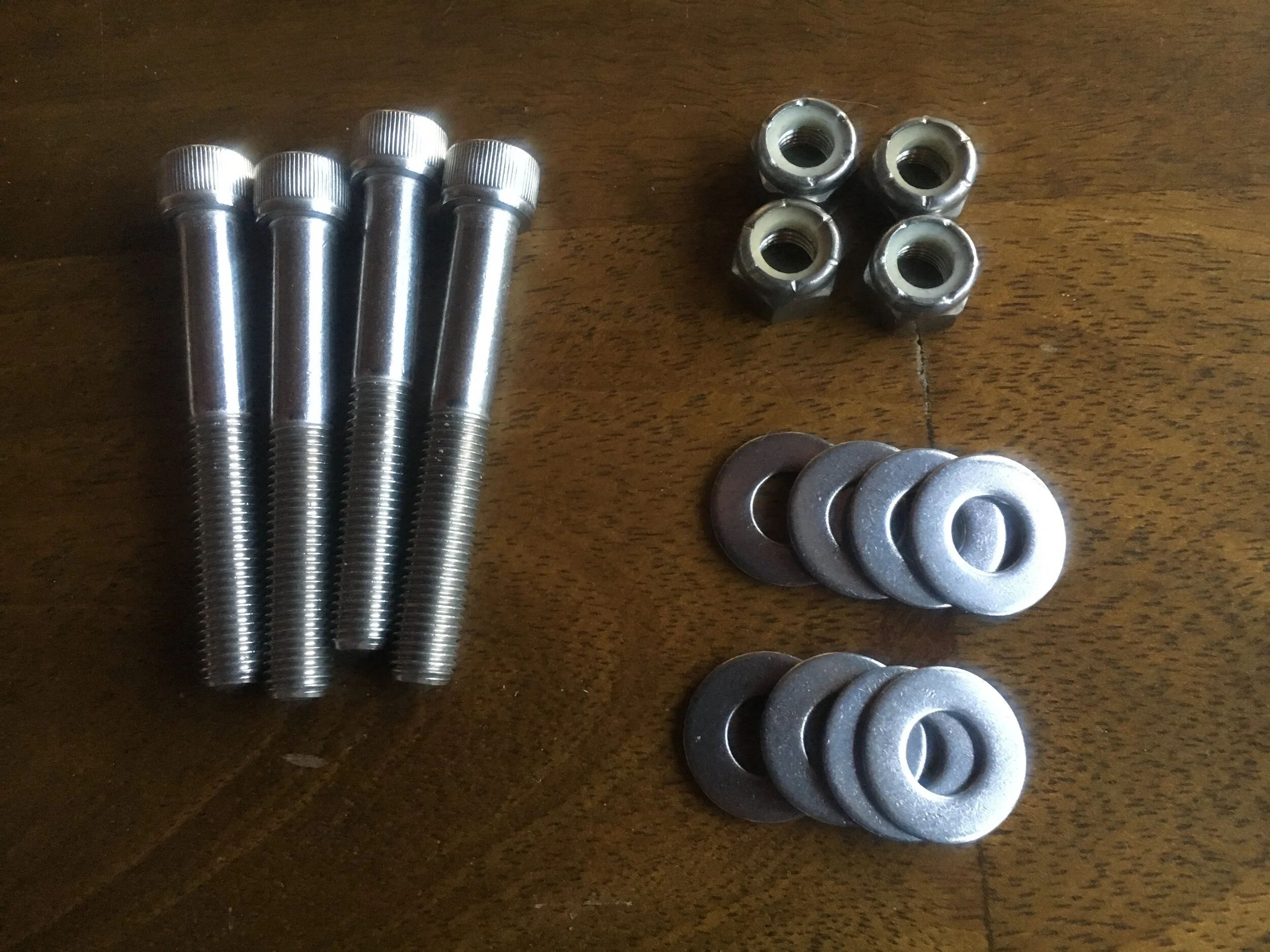
Below are the tools needed to install the Allen screws holding the supercharger onto the mounts. The universal joint and shallow socket work best for the front lower/inner screw’s nylock nut; the short extension and deep socket works best for the rear lower/inner screw’s nylock nut.

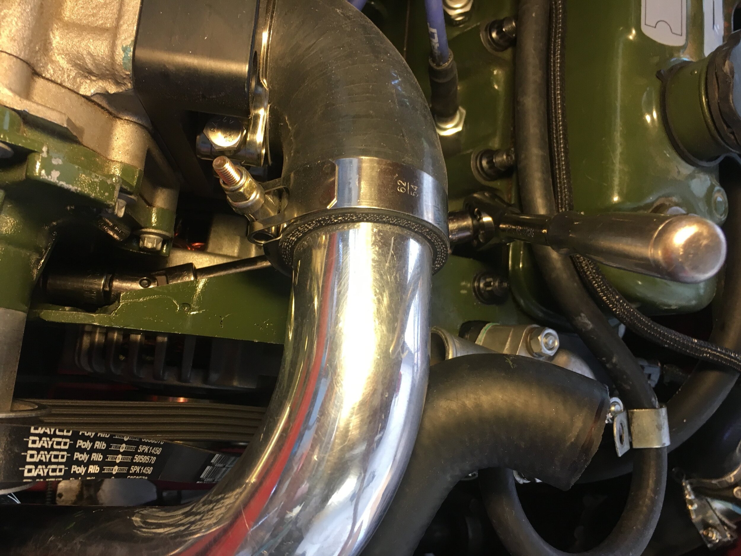
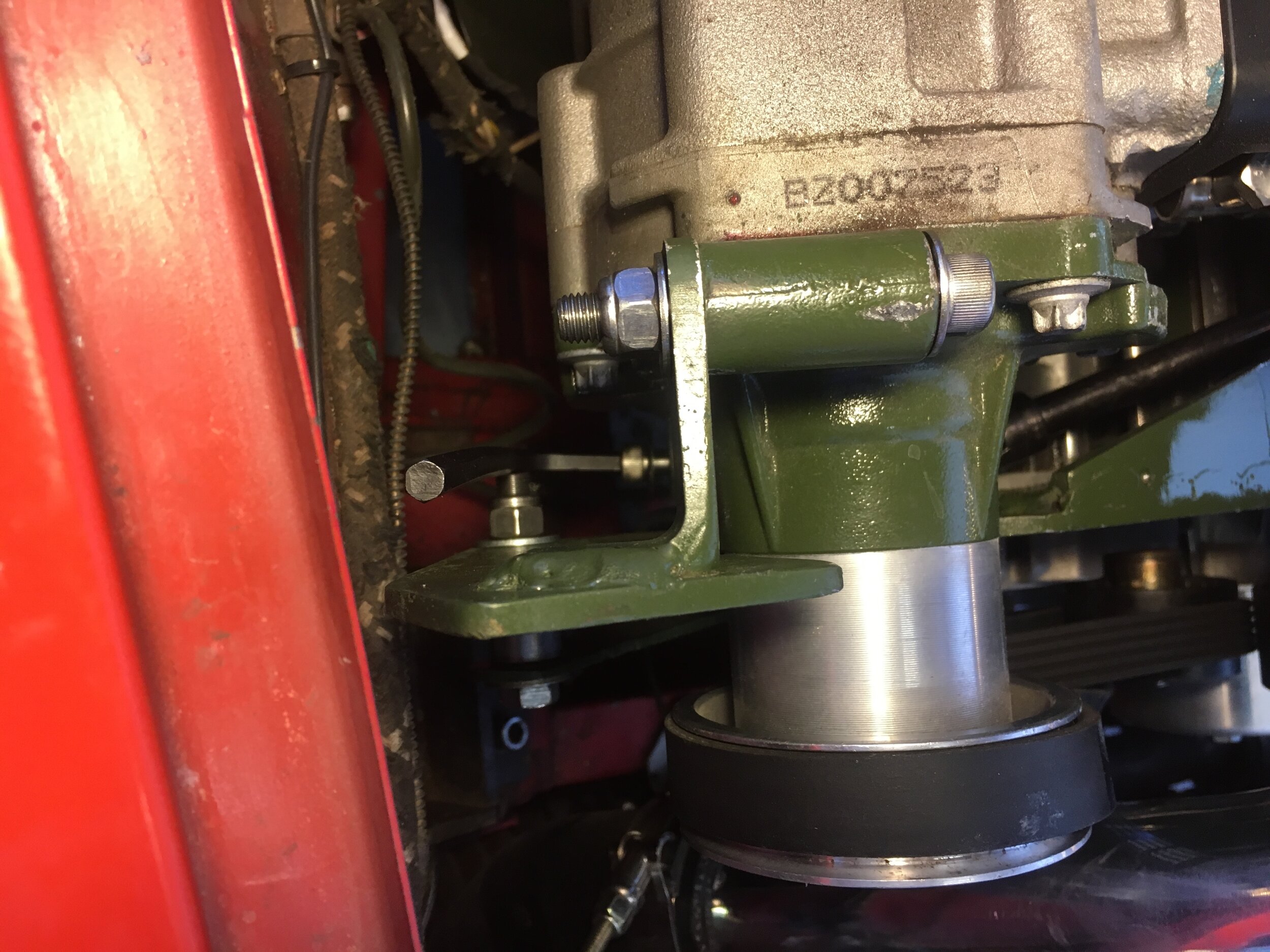
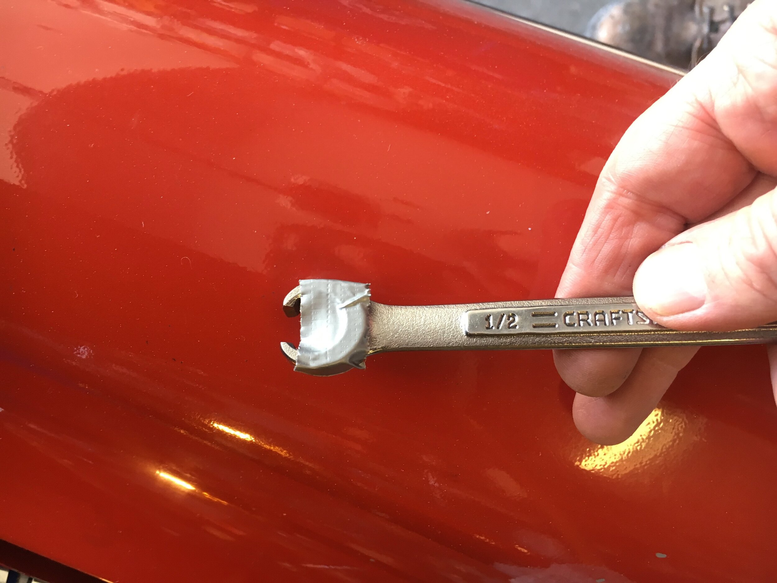
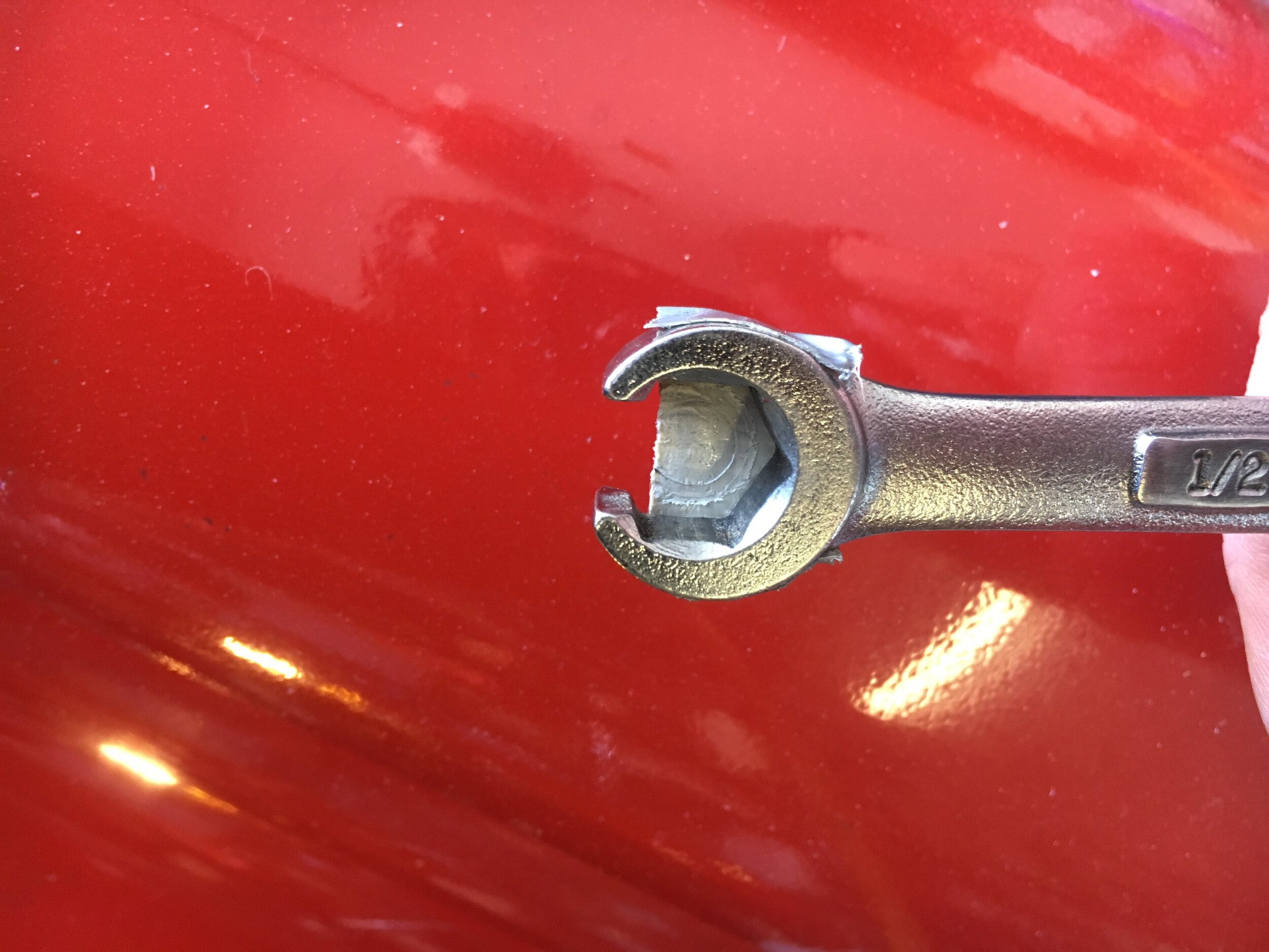
Here are some images of the blower in place. The snout of the supercharger on the ‘67 MG Midget test mule was painted OEM olive green to match the mounts and engine for visual continuity:
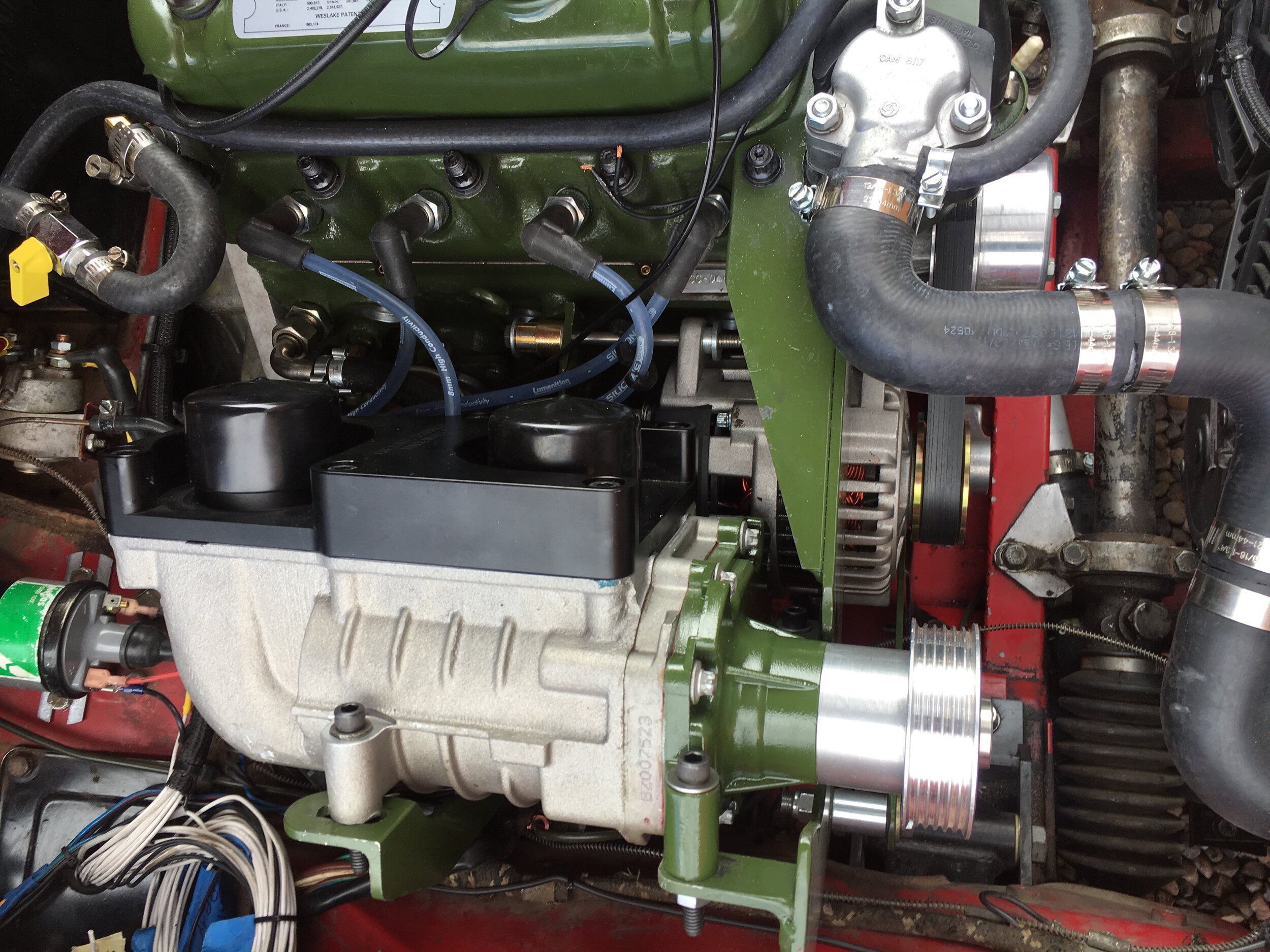
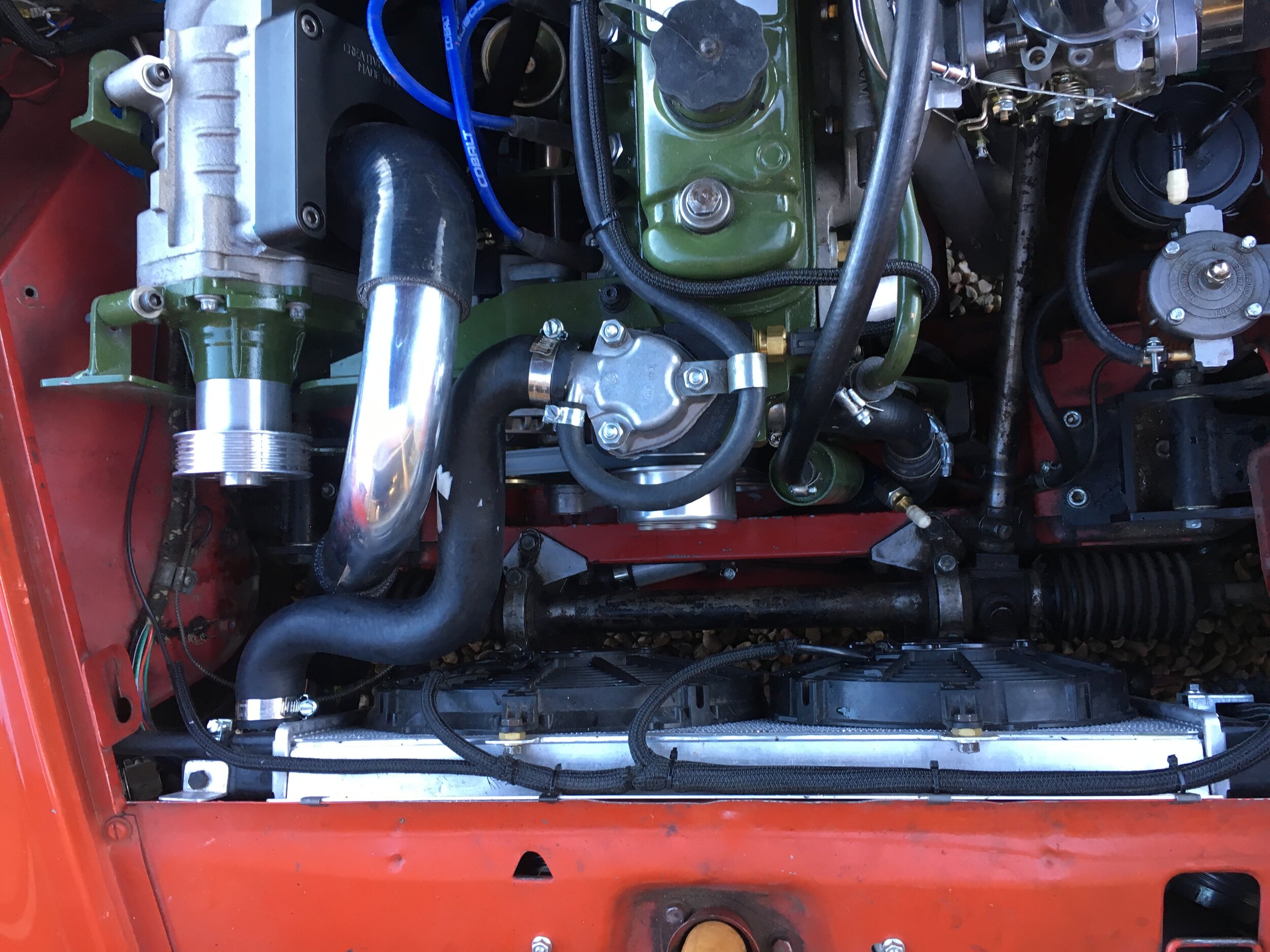
Note that the above installation features a dual-pass, crossflow aluminum radiator from a VW Rabbit with electronically controlled, low-profile fans for vastly improved ‘set it and forget it’ cooling. The instructions for that DIY conversion are located here.
Third, loosen the two 5/16” bolts affixing the rear mount to the block slightly—just enough to allow you to nudge the mount to the center of its travel:

Next, move the supercharger in a fore-aft plane until the screws are roughly in the center of their range in all four of their mounting ears, as shown here at the rear mount:

Note that while the front mount is extremely rigid in both planes due to its combination cantilever and stressed-member design, and its diagonal support strut, the rear mount may flex slightly in a fore-aft plane.
This is not a concern and will not affect the rear mount’s durability, as its dual role is limited to supporting the supercharger’s weight in the vertical plane and to help the front mount resist belt tension in a horizontal or inboard-outboard plane. The 3/16” mild steel oriented perpendicular to those planes is more than adequate for these purposes.
This flexibility is mentioned solely to alert you that during the pulley alignment process, you may need to ‘over-adjust’ slightly at each respective tab, and alternate between screws, to compensate.
Now, choose a screw to act as a pivot for the supercharger vis-a-vis its long axis during the next few steps. Perhaps most convenient is the rear upper screw, but you may find that another screw works better for you:

Fourth, take a long straight edge (an ordinary framer’s or carpenter’s square is used in these photos) and lay it first along the supercharger pulley and the water pump pulley above the supercharger pulley’s shaft, and then along the supercharger pulley, the alternator pulley, and the crankshaft pulley below the supercharger pulley’s shaft.
Alternate back and forth as you align the supercharger pulley, like this:
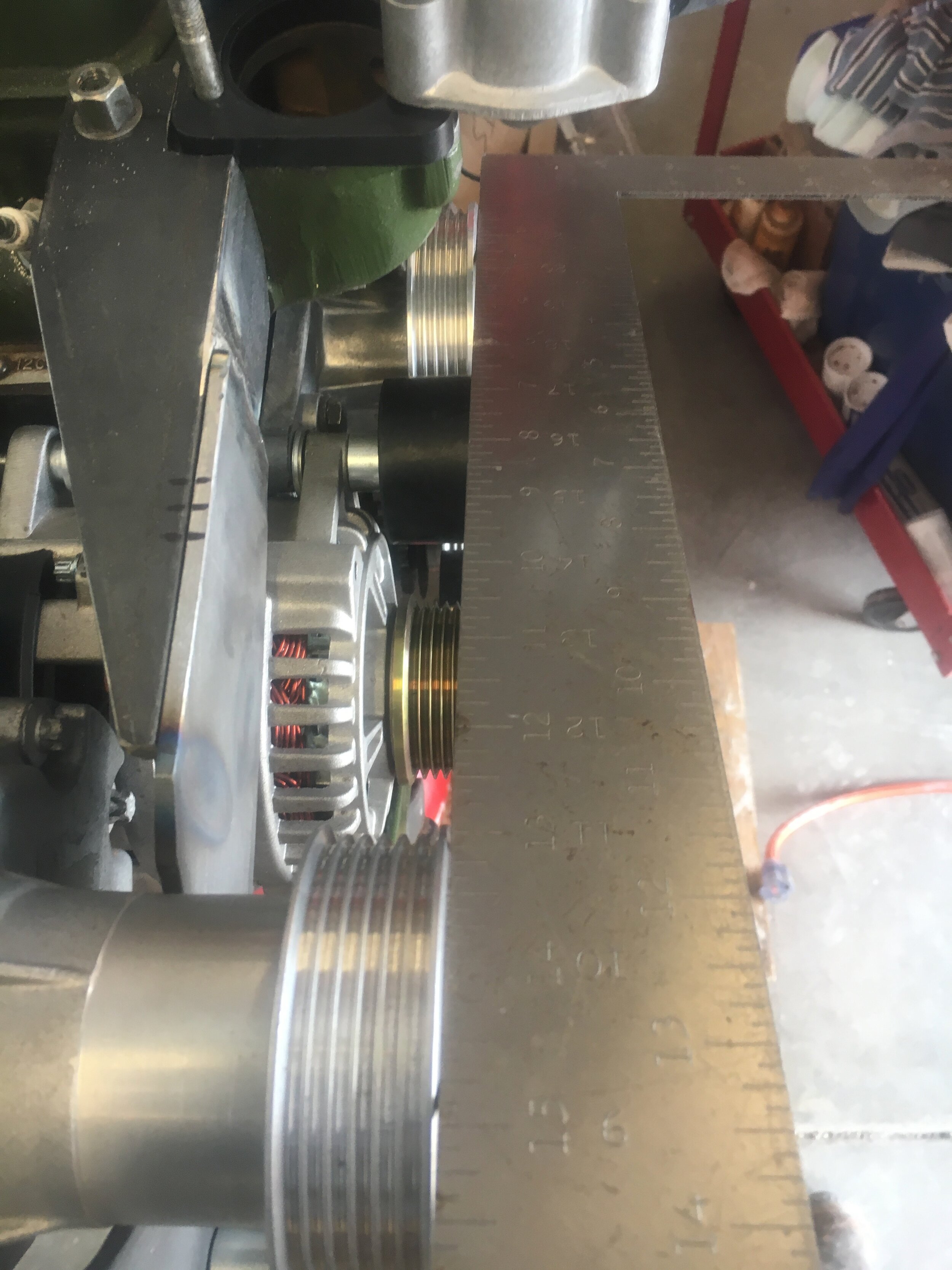
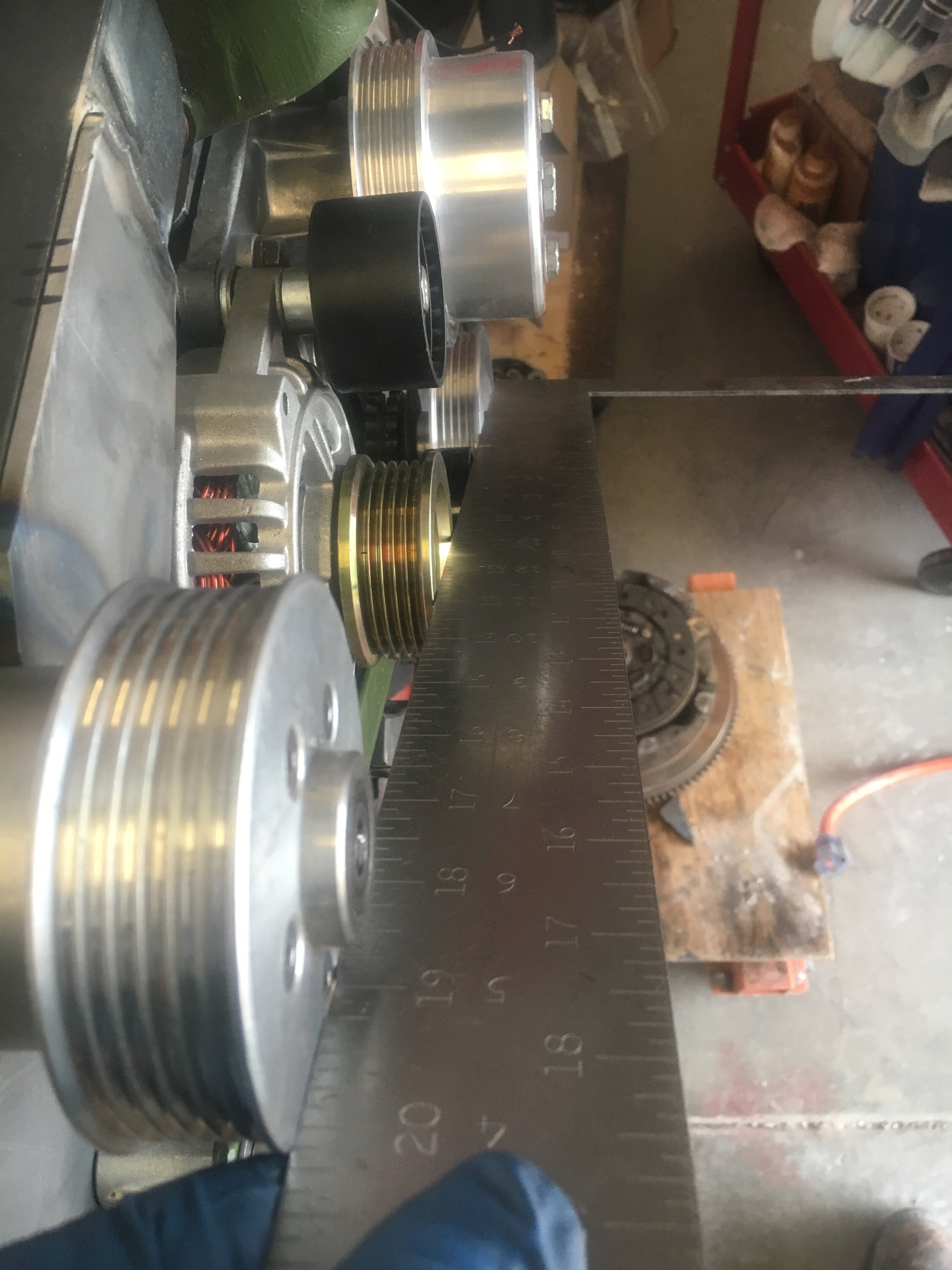
Your first objective is to align the supercharger pulley in a fore-aft plane vis-a-vis both the water pump pulley, and as regards the alternator and crankshaft pulleys.
The serpentine belt conversion instructions are available here.
During this process, you may experience what should be the only complication—assuming that the mounts were correctly fabricated: the supercharger pulley may become misaligned along its long axis. If you were to lay your hand atop the M45 manifold and rotate it as if sanding its top surface, you would be moving your hand in this plane.
Here is an image showing this kind of misalignment—which is easily corrected:

To correct this kind of long-axis, single-plane misalignment, simply tighten your chosen pivot screw more firmly than the three other screws, and rotate the supercharger incrementally in that dimension—and then lay your straight edge along the supercharger pulley and alternator pulley below the supercharger’s shaft.
Once again, you may find that a different screw facilitates this particular rotation better than your first choice.
Here is an image showing correct alignment in this long-axis plane:

Do not drive yourself crazy trying to get perfect long-axis alignment—i.e., using a feeler gauge, etc. It does not have to be perfect, just reasonably close.
If you cannot achieve fairly close alignment in this axis, the solution is simply to get out your die grinder, Dremel, or round hand file, and elongate the slots on the mounting tabs a bit to allow greater rotation along the blower’s long axis.
Note, however, that an alternate cause could be that you did not position the rear mount carefully at the outset. It should be both in the middle of its fore-aft travel as discussed above and roughly parallel to the front mount, as shown here (the measurement per se is not critical; it is a comparative measurement—i.e., the spread at the bottom of the blower versus the top):

Finally, once you have achieved correct fore-aft and long-axis alignment—typically, two or three cycles of the above process—securely tighten all of the bolts and screws.
install the serpentine belt
Switching to the longer belt to drive the supercharger may be very straightforward, but two complications addressed in this section may arise. If you ultimately cannot install the default Dayco # 5050570 belt because it is too short, or if it is too loose, there are longer and shorter belts in the parts list.
Ordinarily, you simply release the belt tensioner, remove the short naturally-aspirated belt, and install the longer supercharger drive belt, routing it as shown in the second image in this slideshow:
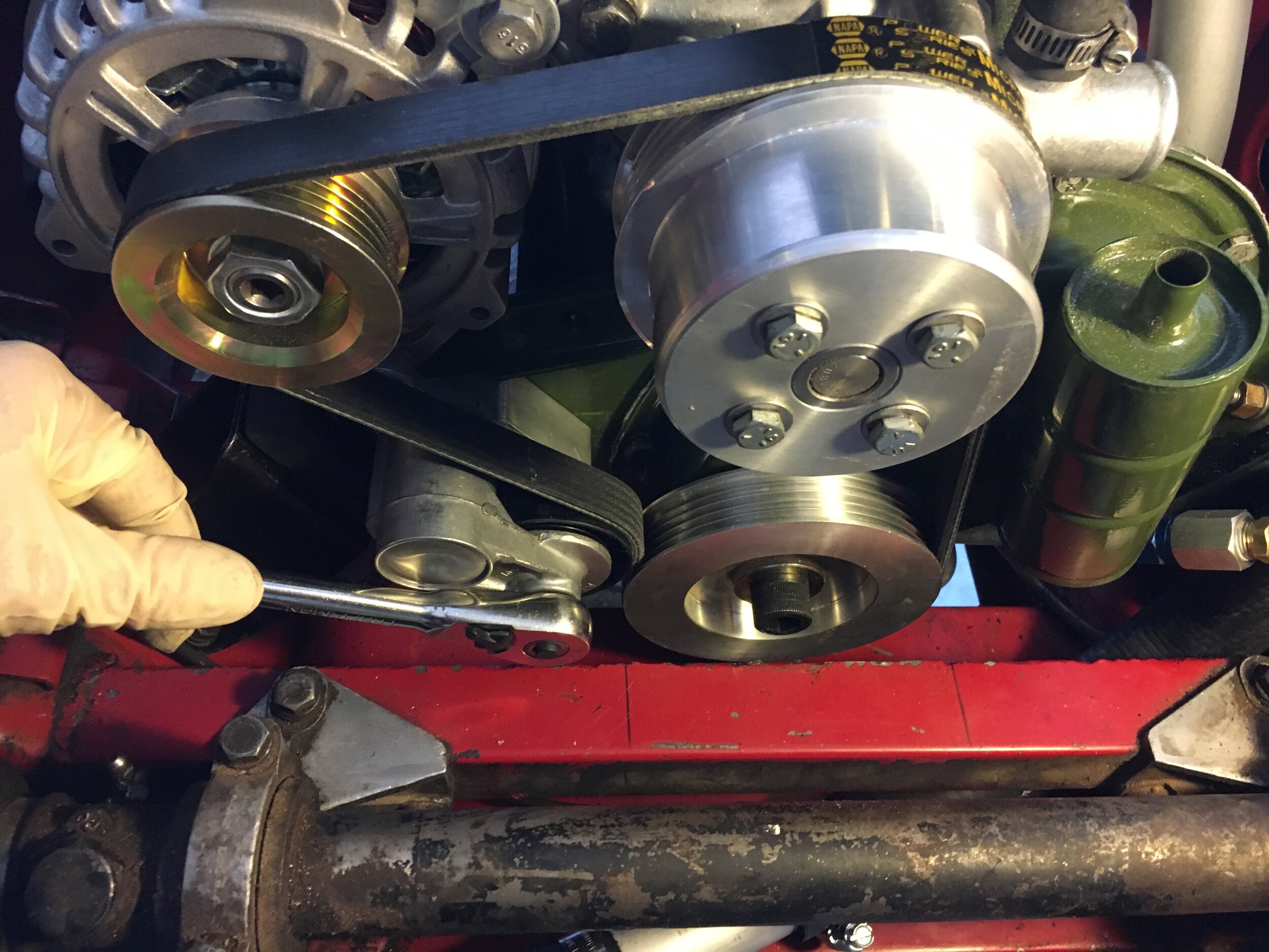
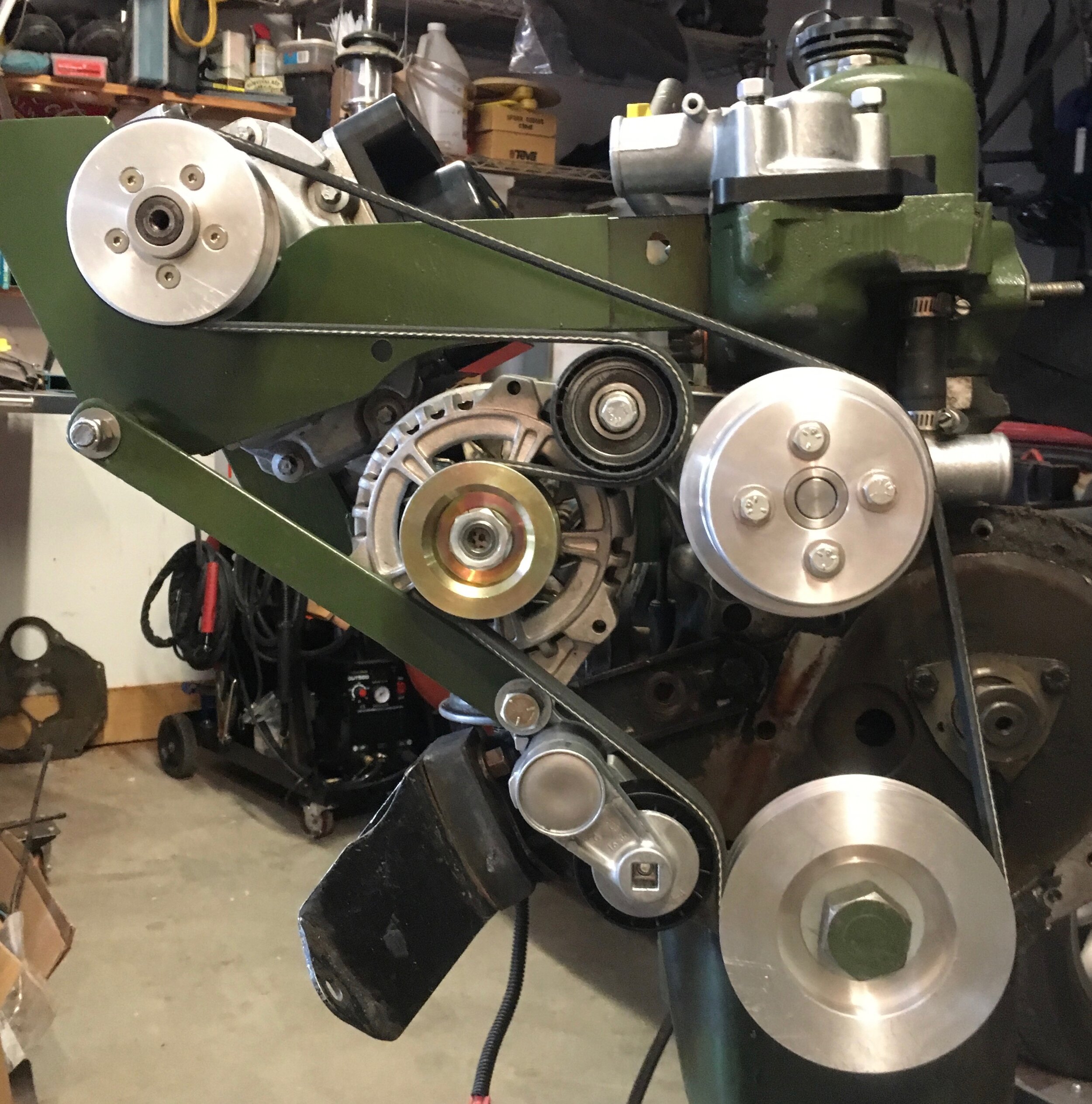
The easiest method of installing the belt we have found is to finish with either the blower pulley or the water pump pulley. That said, proceed as follows:
Use a 3/8” ratchet to relax the tensioner and pass the belt around the crank pulley, then release the tensioner;
Pass the belt around the alternator, the idler, and then slip it over the water pump pulley;
Use the ratchet to relax the tensioner again, and slip the belt under the supercharger pulley as far as you comfortably can;
Holding the belt in place on the supercharger pulley, release the tensioner, grab the water pump pulley, and exerting rotational force with both hands, walk the belt onto the supercharger pulley as you turn the engine (this will be easier with the spark plugs removed).
Now, sight along the belt from the supercharger pulley to the water pump pulley, and determine whether the belt needs to ride on the rear or front 5 grooves of the supercharger pulley.
Ours needed to be walked onto the rearmost groove, using the method in the last step in the above sequence while deflecting the belt rearward or forward:

Next, sight along the top of the belt from the super charger pulley underneath the top radiator hose to make sure the belt is not contacting the hose as shown in the next photo series.
Remember that the engine will twist slightly from the increased torque, and the radiator hose is attached to the radiator—which is fixed. Therefore, you should at minimum be able to fit your forefinger or (better yet) thumb between the belt and hose, or the last photo reveals what could happen. Be sure to check for this kind of damage early into your tuning sessions after a few full-throttle runs:
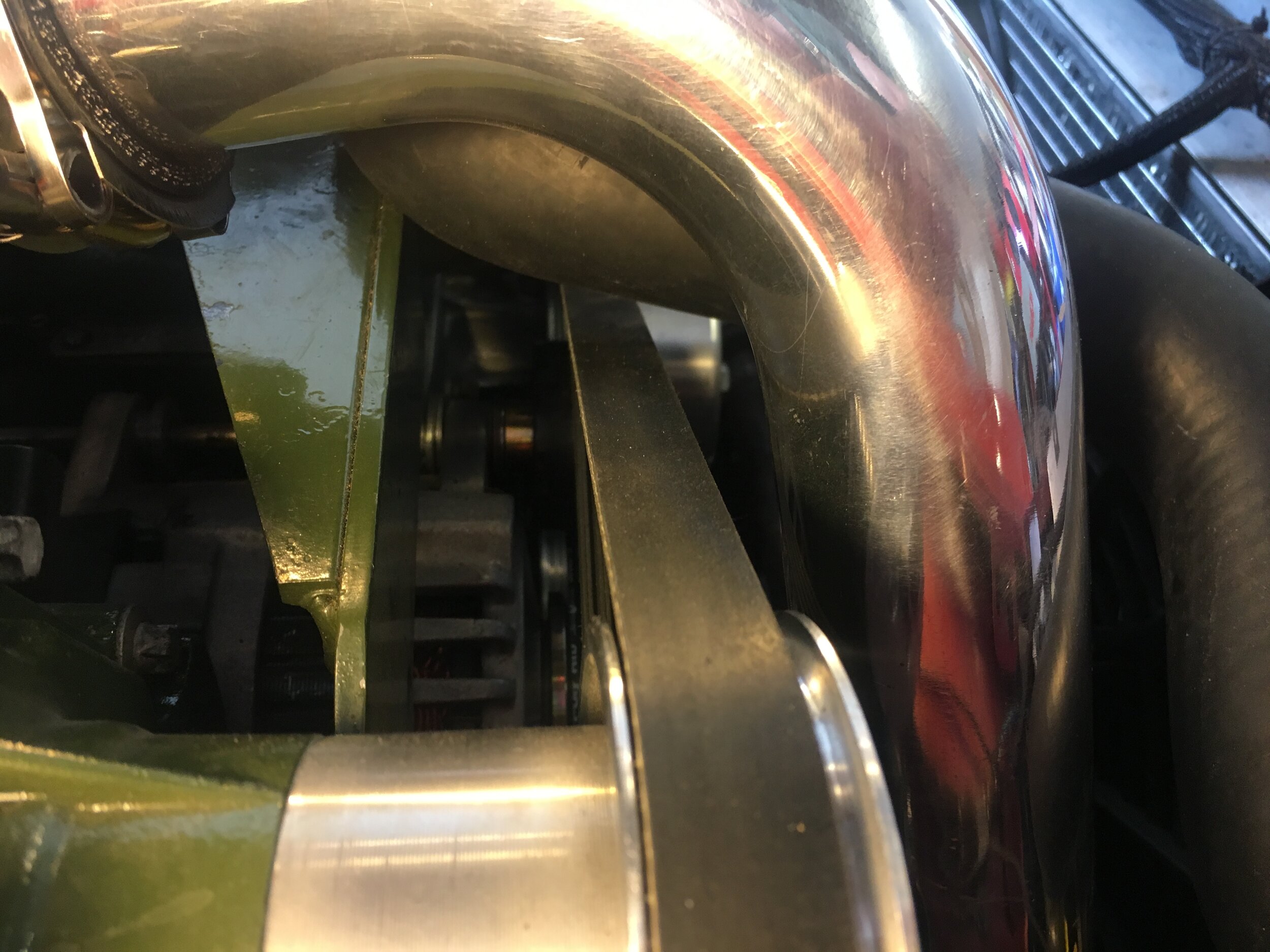
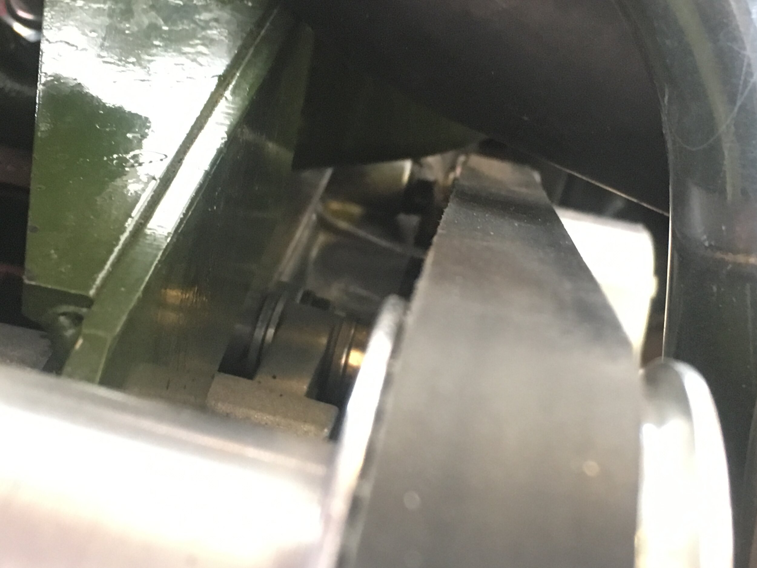
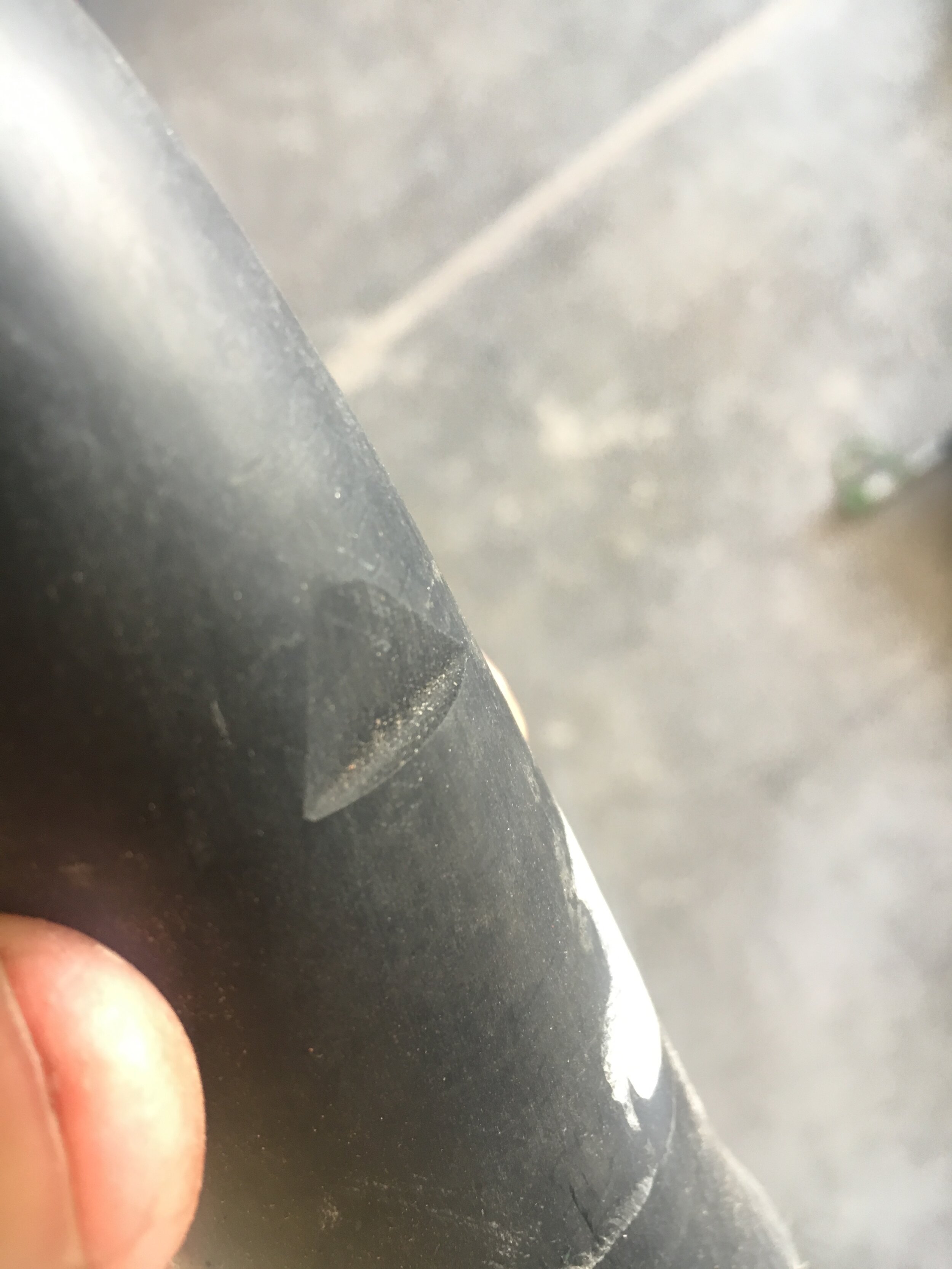
If there is contact or insufficient clearance, put a rag under the top hose at the thermostat outlet, loosen the clamp, grab the hose with a pair of water pump pliers (if adhering), and rotate it slightly to lift the hose away the belt.
Tighten the clamp while holding it a bit higher than you want, as it may sag slightly. Repeat this process with the other end of the hose at the radiator inlet.
Finally, do not raise the hose so high that it contacts the supercharger’s outlet snorkel. You do not want hot water leaving the cylinder head to superheat the blower’s output, as that would counteract the effect of the intercooler:

If raising the radiator hose to create sufficient clearance above the serpentine belt creates contact with the blower’s aluminum outlet snorkel, simply loosen the T-bolt clamps on the blower’s silicone reducing elbow and rotate it clockwise, thus shifting the aluminum snorkel away from the radiator hose.
Doing this will raise the radius of the aluminum snorkel, but there is ample room under the bonnet at this point, as seen with this Play Doh clearance test. Look carefully and you can see that the top of the little peak has been flattened by the bonnet when pressed fully closed:


plumb the intercooler - r/h side
Here is a diagram of the snorkels when complete to orient yourself with the objective in the next few sections:

Here is a similar diagram of a Morris Minor engine bay:
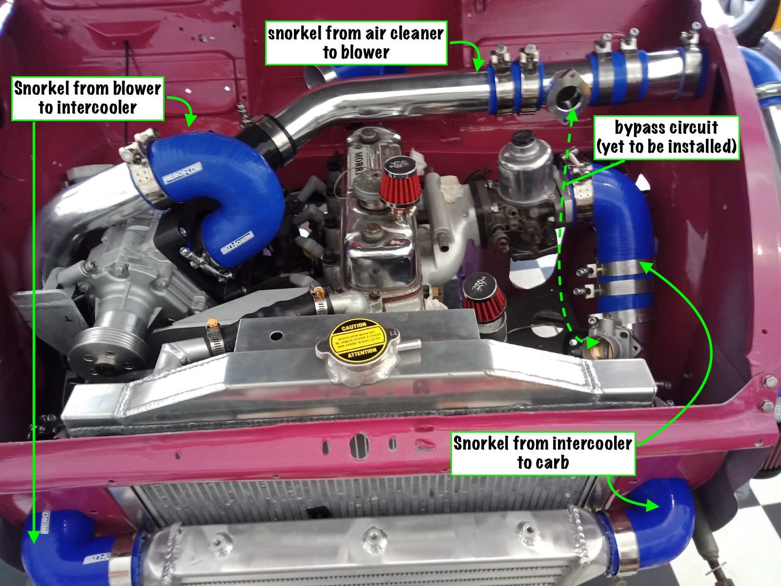
Note: if you were not installing an intercooler, you would merely run a pipe around the front of the engine. The ‘snorkel to carb’ 45-degree elbow in the above image would be replaced with a 90-degree elbow connected to the forward ‘blow-off’ pipe that mounts the bypass valve—and which would connect to the blower’s outlet.
Now that the supercharger is installed and the longer belt fitted (at least temporarily), you can plumb the right-hand side of the intercooler. Perhaps the least-expensive route is to purchase a 2” (51mm) turbo pipe kit, similar to the one in the parts list, such as this one, even though many of the parts are left over:

Begin by trimming the large leg of a 2.5” to 2” silicone reducing elbow (not included in the above kit but reflected in the parts list for this conversion), to reduce its profile above the M45 manifold. You may or may not have to trim the small leg—which aims forward.
Your aim is to provide an air gap between the radiator hose and outlet pipe:

Do not worry—there is ample vertical clearance under the bonnet, as this Silly Putty test demonstrates (the bonnet was closed and just barely touched the putty):
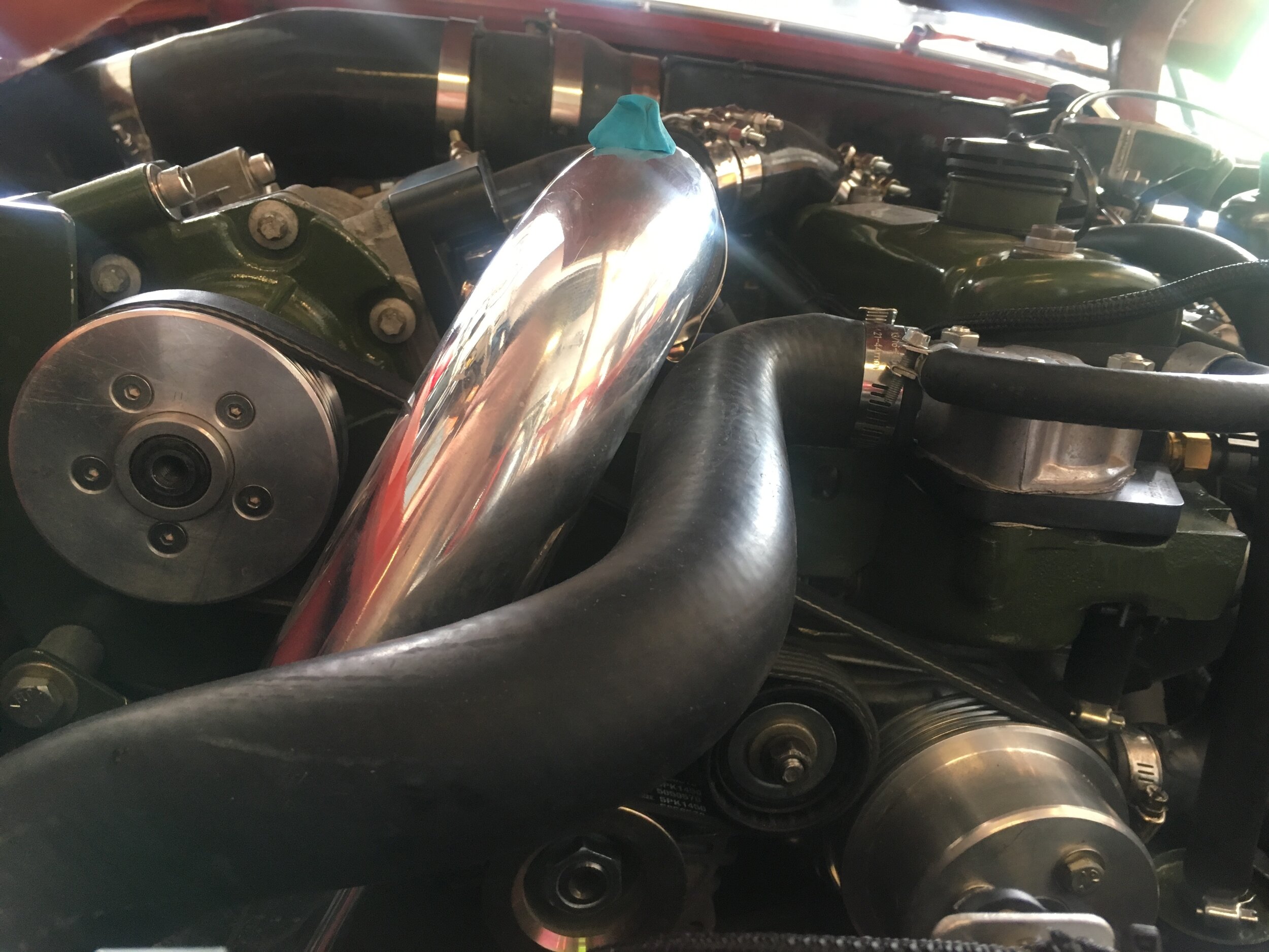
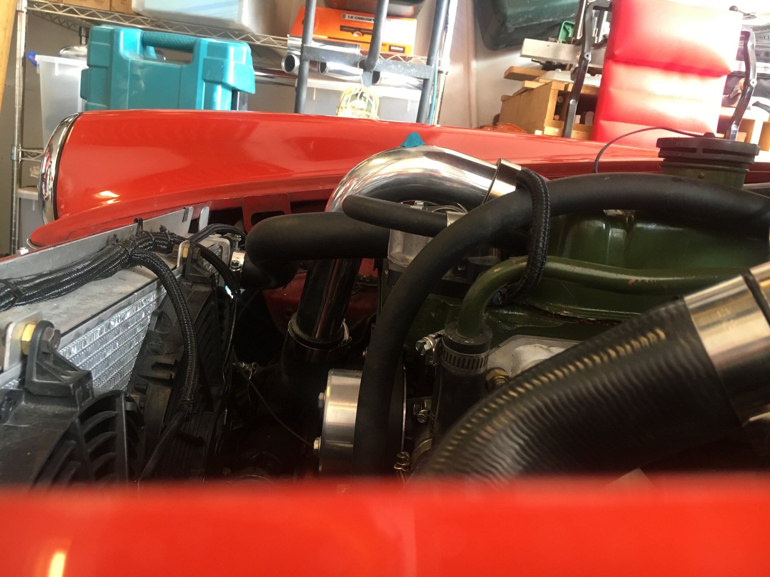
To form the outlet pipe shown in the above photos, you will trim both ends of one of the 90-degree aluminum pipes with a hack saw or band saw. This will remove the barbs molded into the aluminum, but at the low pressures most people will be running (5~8 psi), this is not a concern.
The first cut, which forms the shorter leg arching over the belt, is approximately 6-5/8”, after which you should break the sharp edges with medium grit sand paper. Then, slip the shortened reducing elbow onto the end:
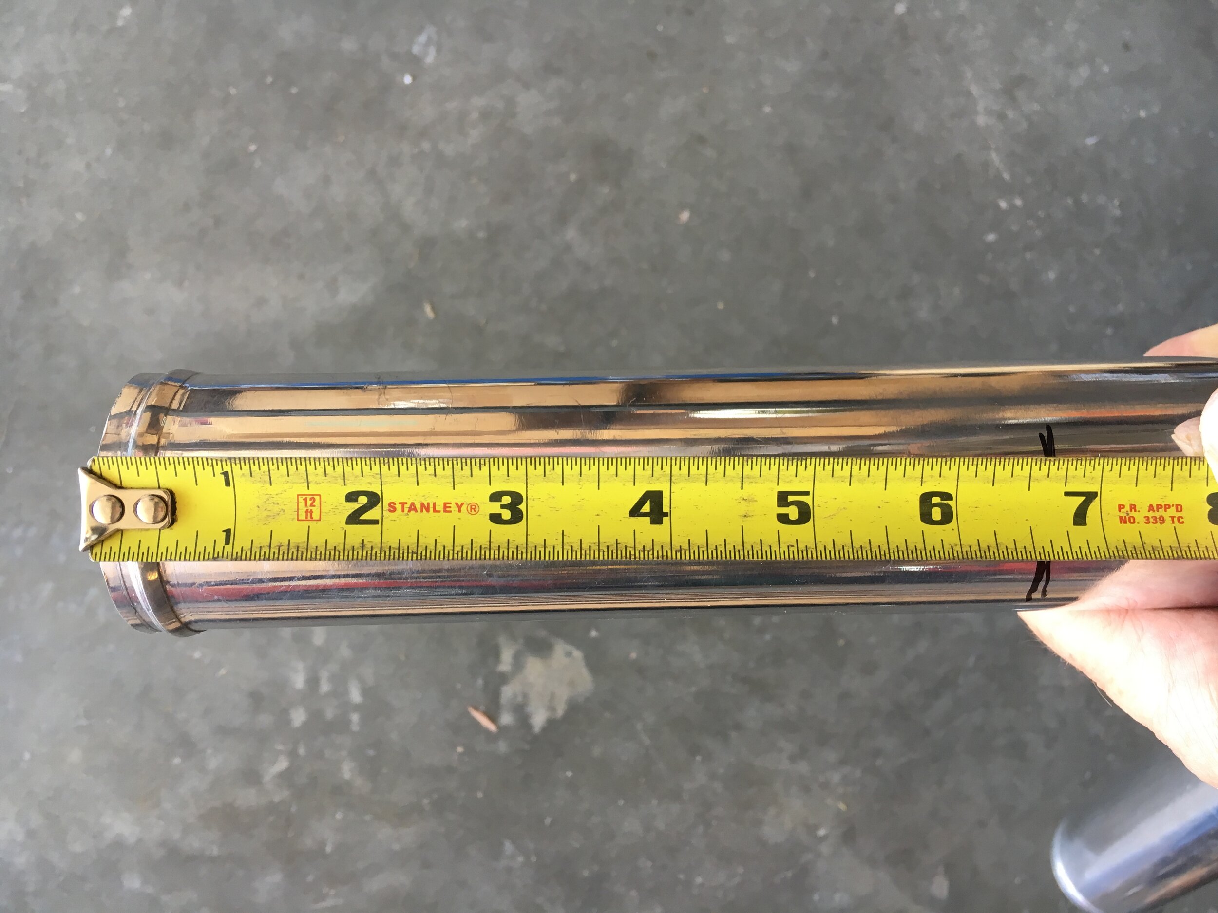
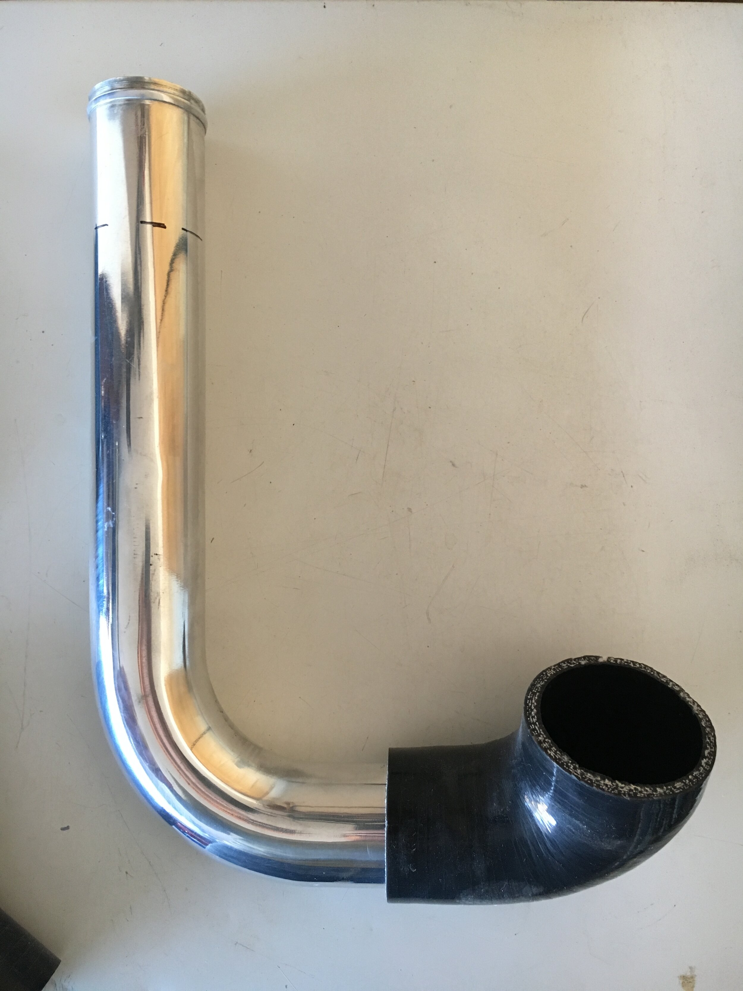
The next cut, which forms the longer leg extending down between the engine and the end of the radiator, is approximately 2-1/2”:

Rotate the reducing elbow and outlet pipe to put the lower end in position to receive either a 45-degree 2” silicone elbow (not included in the kit) or a cut-down 45-degree aluminum pipe from the kit joined with two short straight silicone joiners. Your goal is to put the bend in the 45-degree elbow adjacent to the shock.
The author used the former method, only because he had a 45-degree silicone elbow lying around and this method will use fewer clamps:

The ‘67 Midget in the photos has a Frontline suspension conversion. Many owners will have stock lever shocks and will need to rotate the outlet pipe slightly to shift the silicone or aluminum 45-degree elbow forward a bit.
Next, trim both legs of the other 90-degree aluminum elbow to form a pipe connecting the supercharger outlet pipe to the intercooler’s inlet. The top, longer end of the pipe will insert into the 45-degree silicone elbow as shown in the previous photo or mate with the aluminum elbow via short silicone joiner tubes.
One leg needs to be cut as short as possible while leaving sufficient room to clamp on a shortened 90-degree silicone elbow from the kit, which in turn will connect with the aluminum joiner leading through the front valance sheet metal to the intercooler. The other leg is cut approximately 3-1/2” to form a longer leg that connects with a 45-degree silicone elbow (shown) or aluminum-and-joiner option:
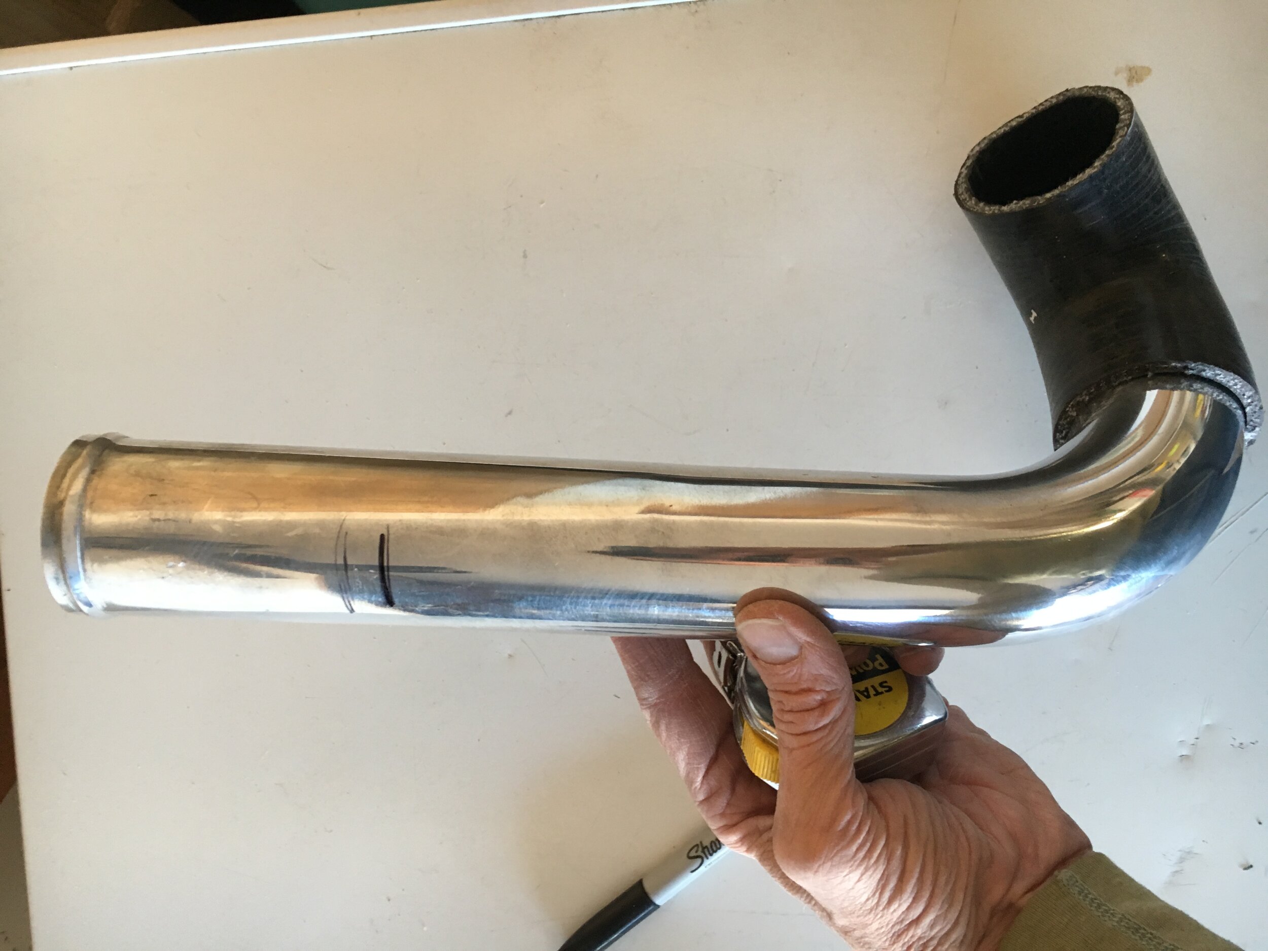
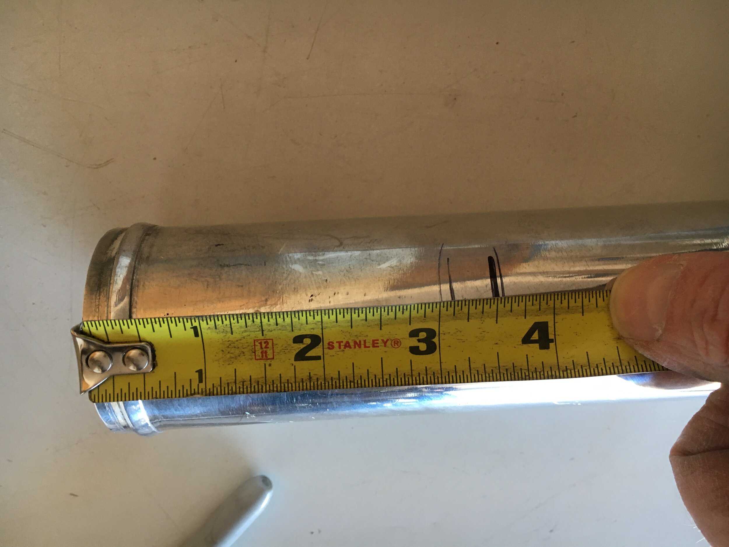
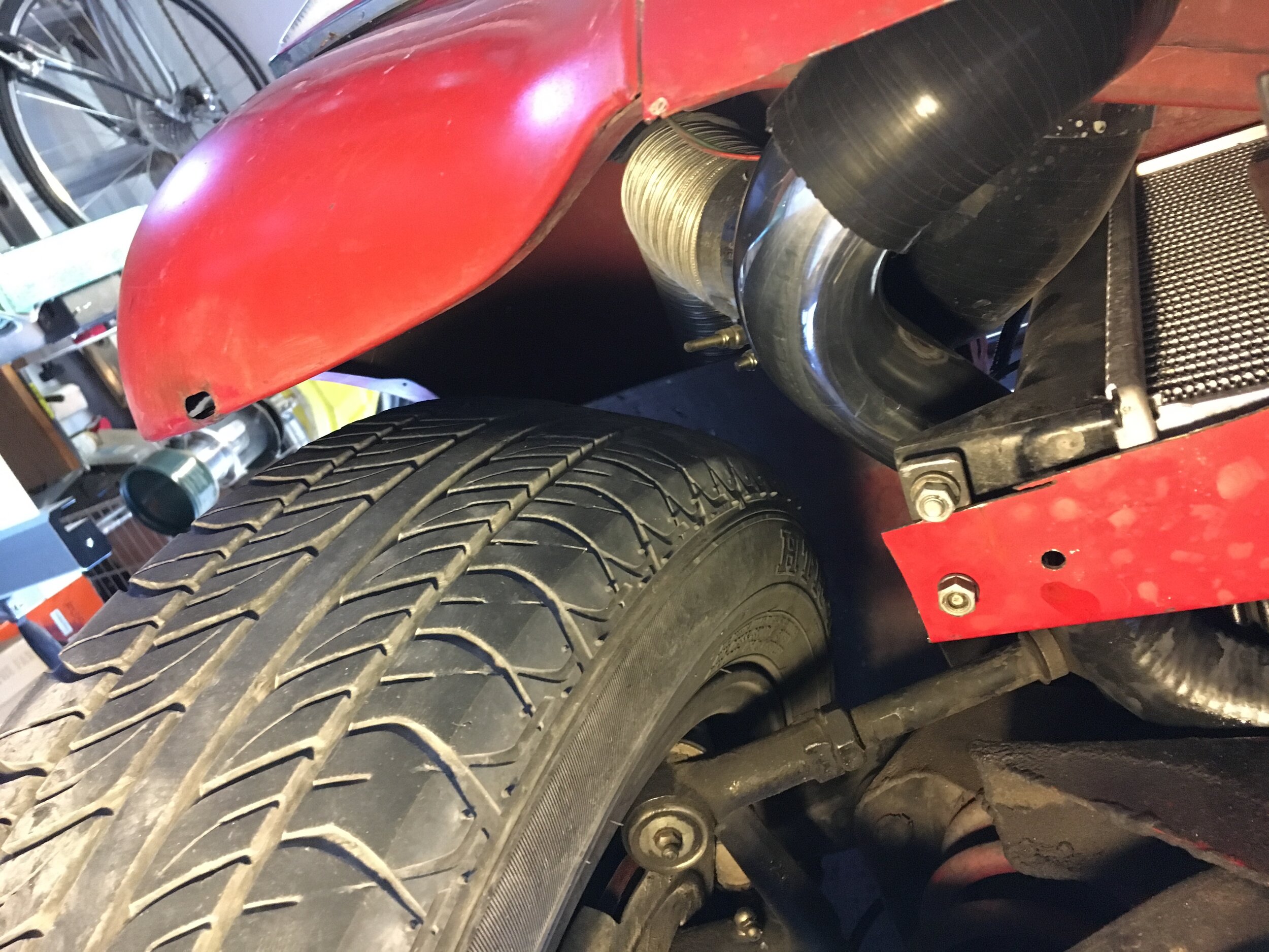
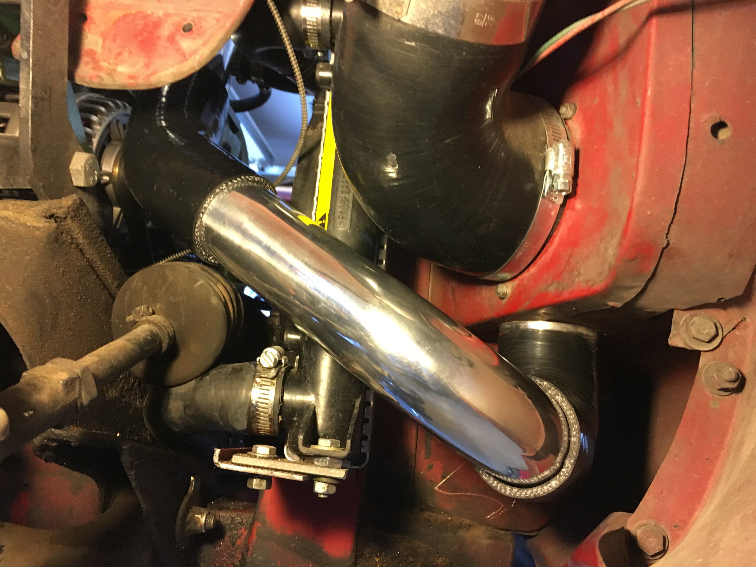
Finally, rotate the pipes and joiners, checking clearance throughout the circuit. Then remove the snorkel from above as a unit and disassemble each section, clean thoroughly inside and out with a damp microfiber cloth or other lint-free rag, and reassemble with T-bolt clamps from the kit:

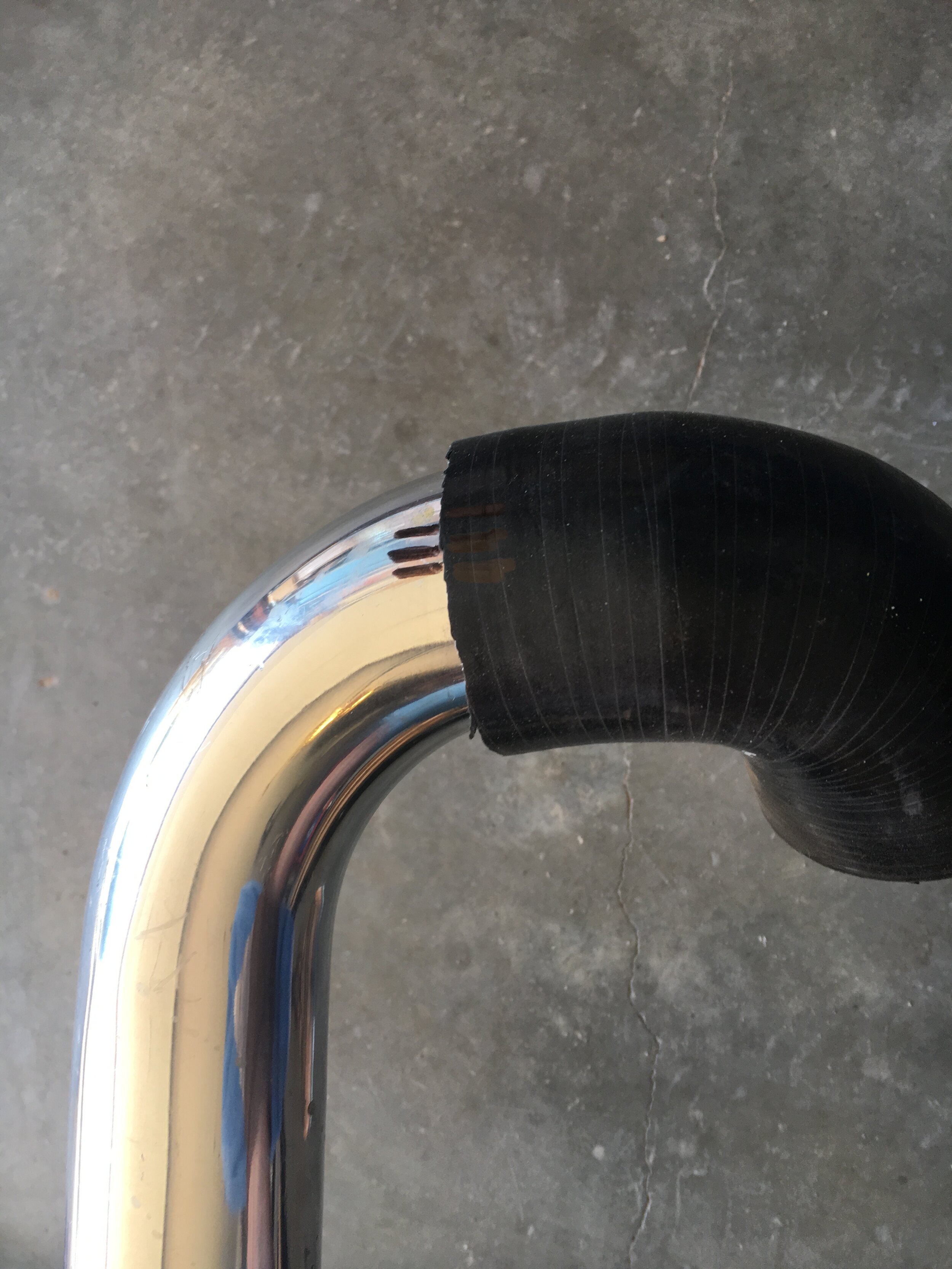
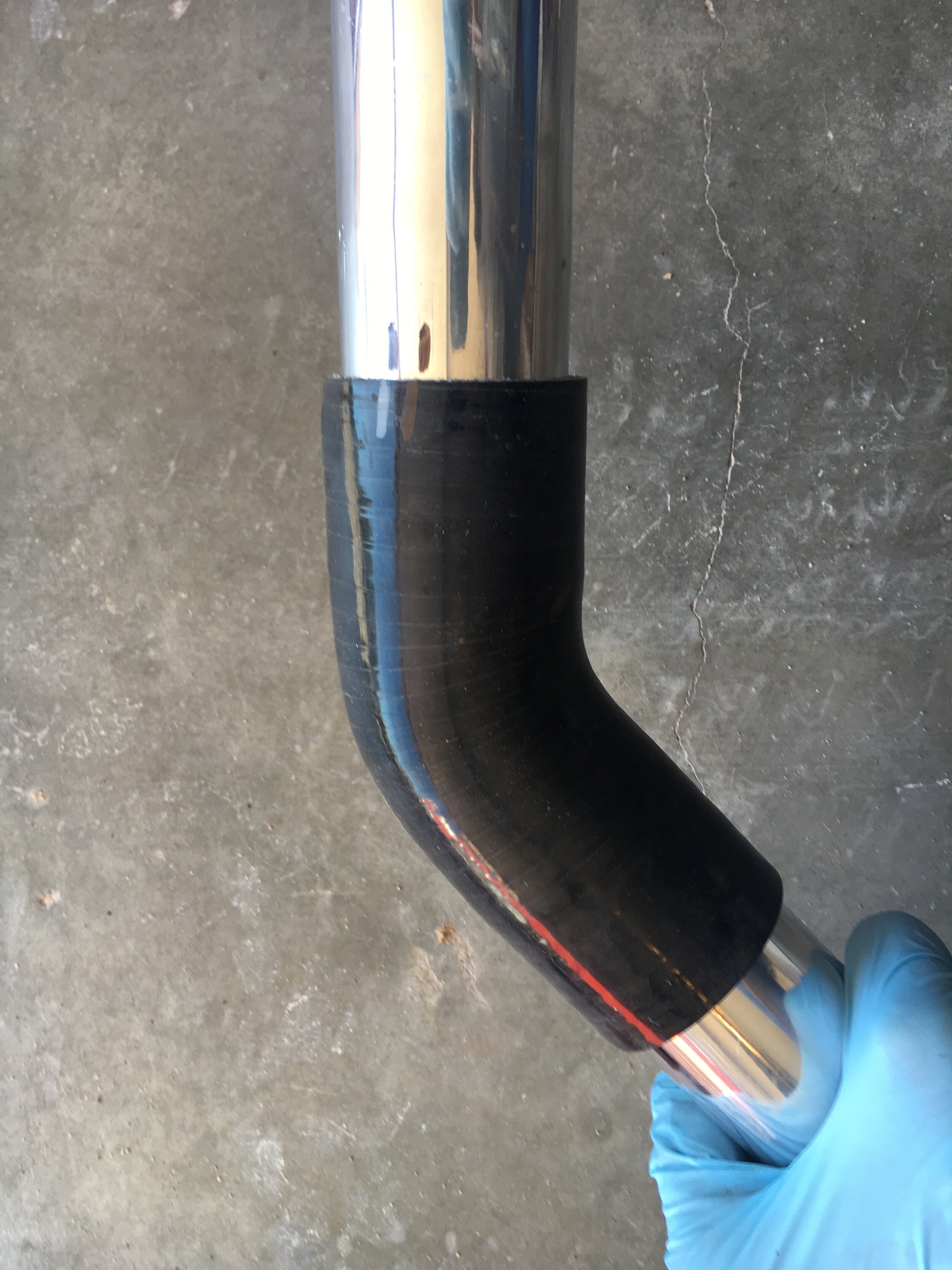
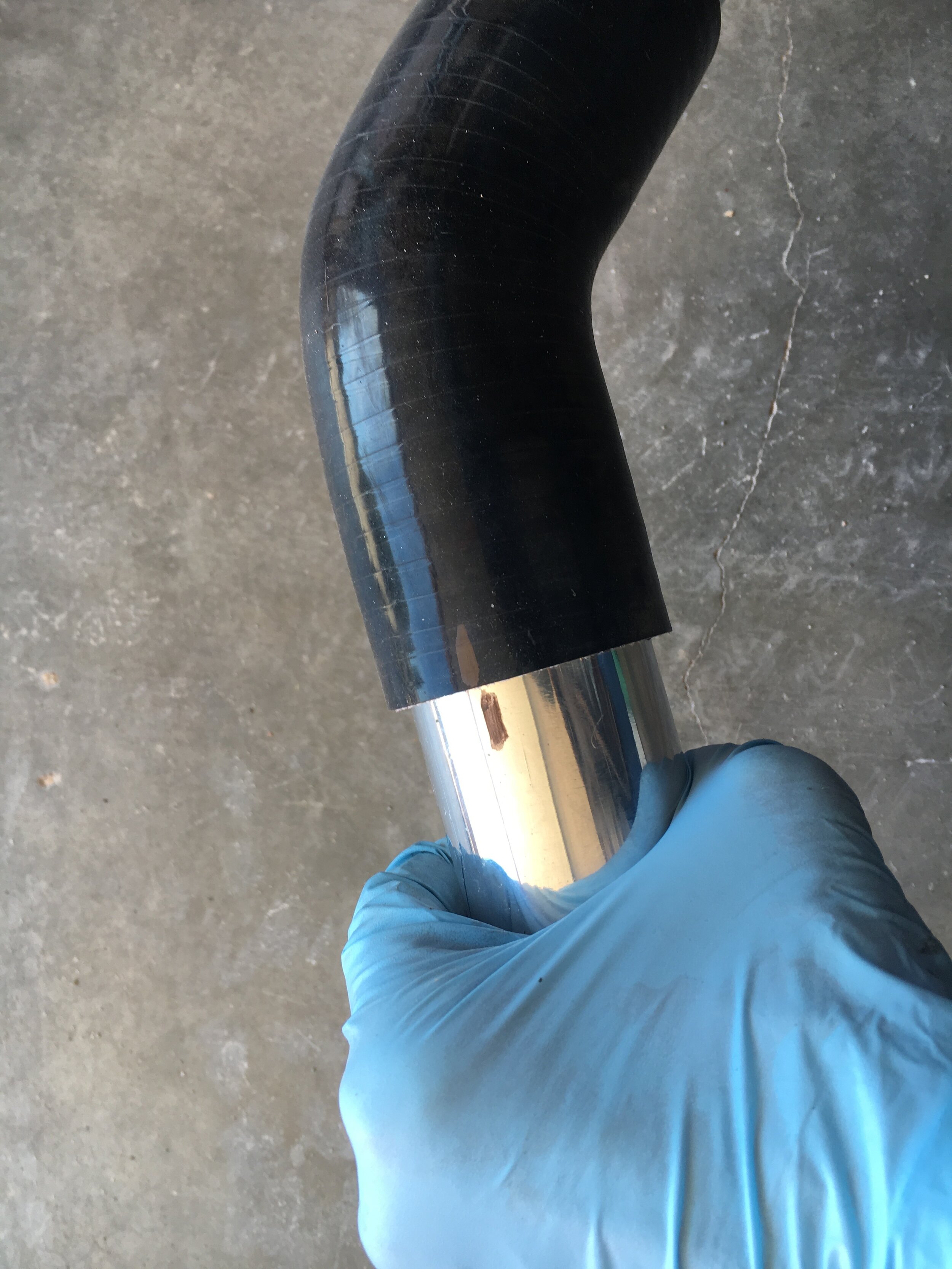
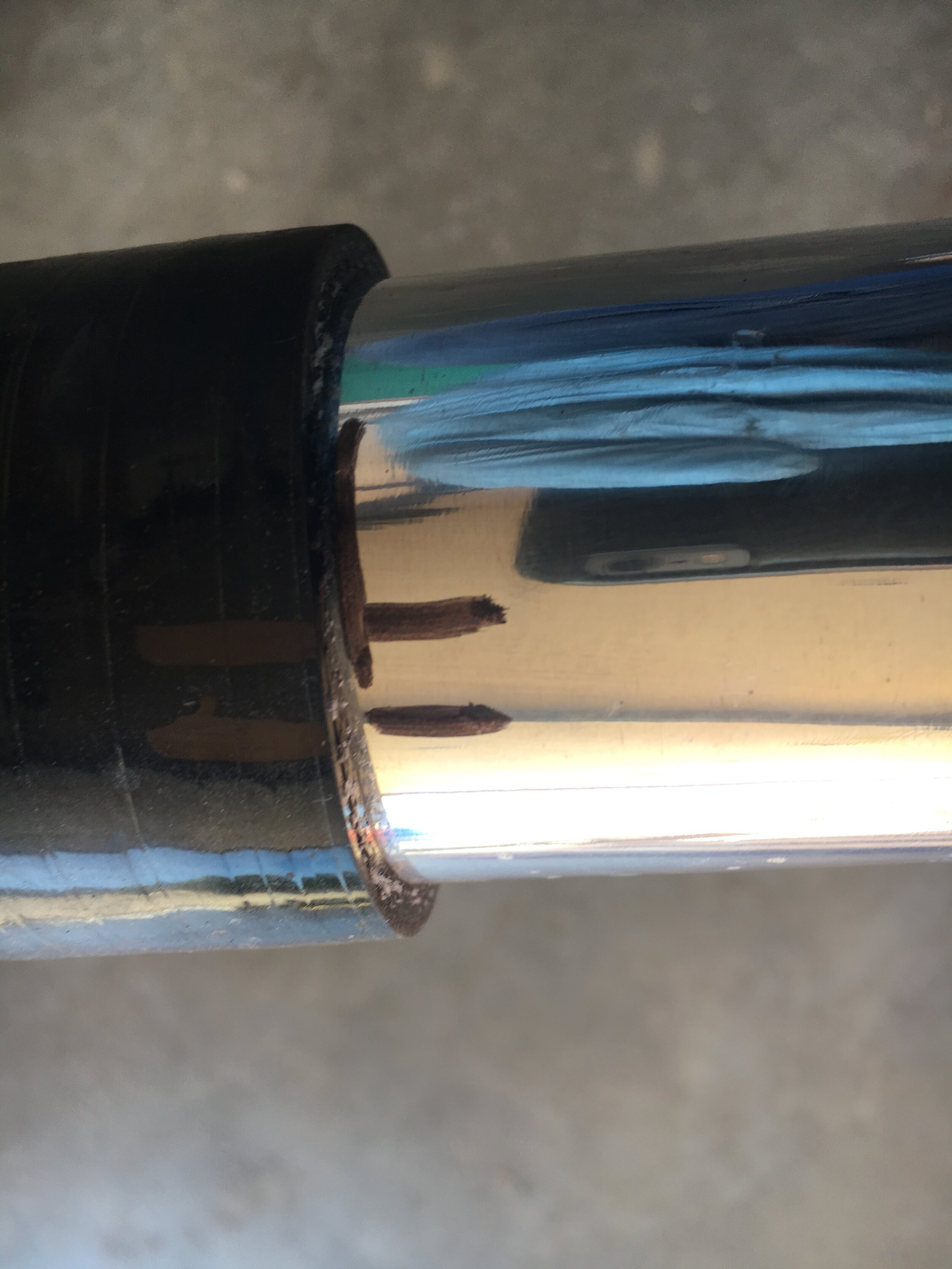
plumb the intercooler - l/h side
Begin plumbing the left-hand side of the intercooler by building the snorkel downward from the carburetor in sections. Be sure to clean the inside of each silicone piece as you proceed, to avoid pumping dust into your engine. You can wipe down the exterior when you finish.
First, assemble the 90-degree 3” to 2.5” reducing elbow, an aluminum 2.5” nipple, and a 45-degree 2.5” elbow, leaving the clamps loose to allow adjustment:

Second, install the assembly and rotate the reducing elbow so that the snorkel lies beneath the level of the fender or wing:
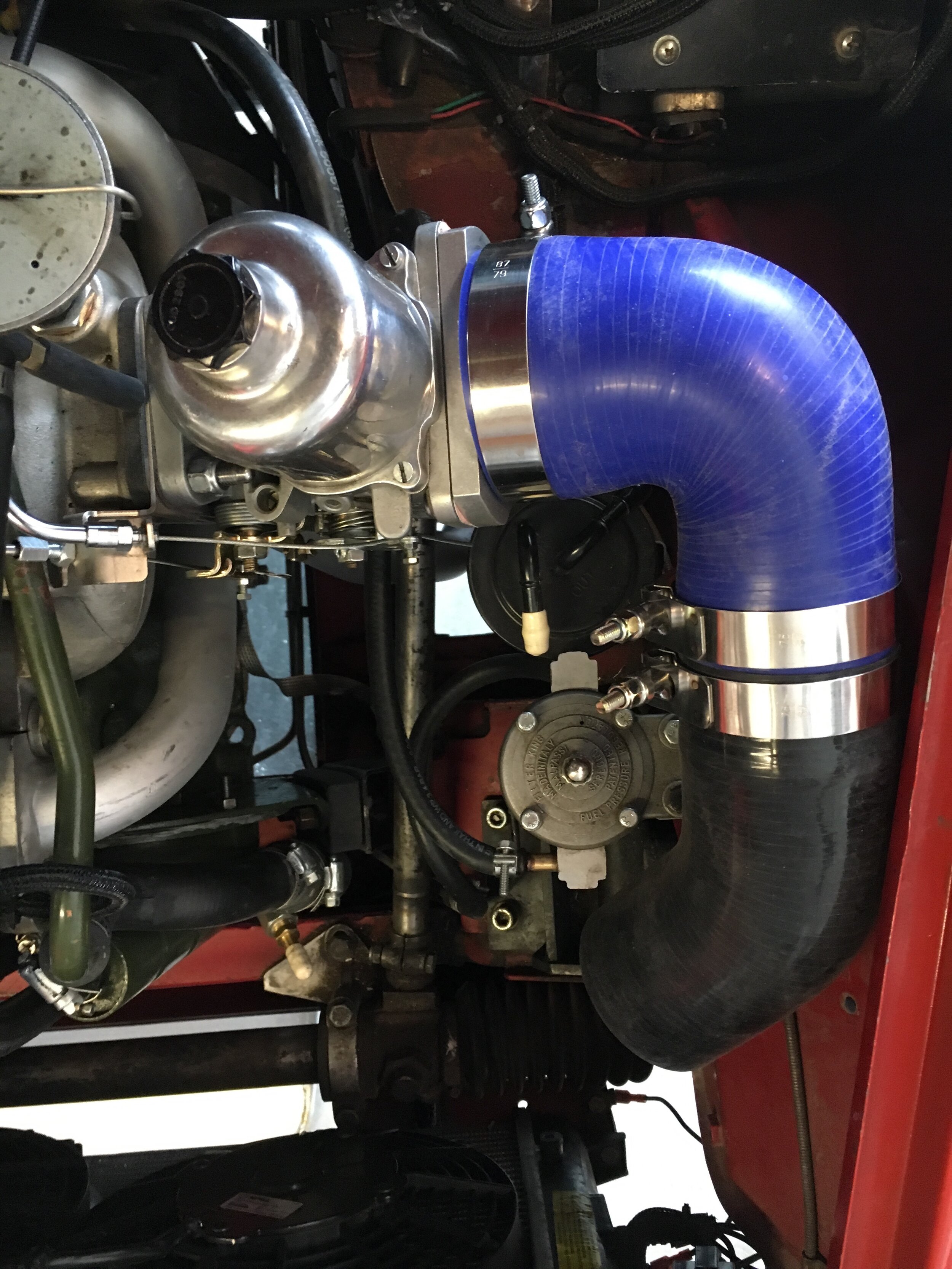
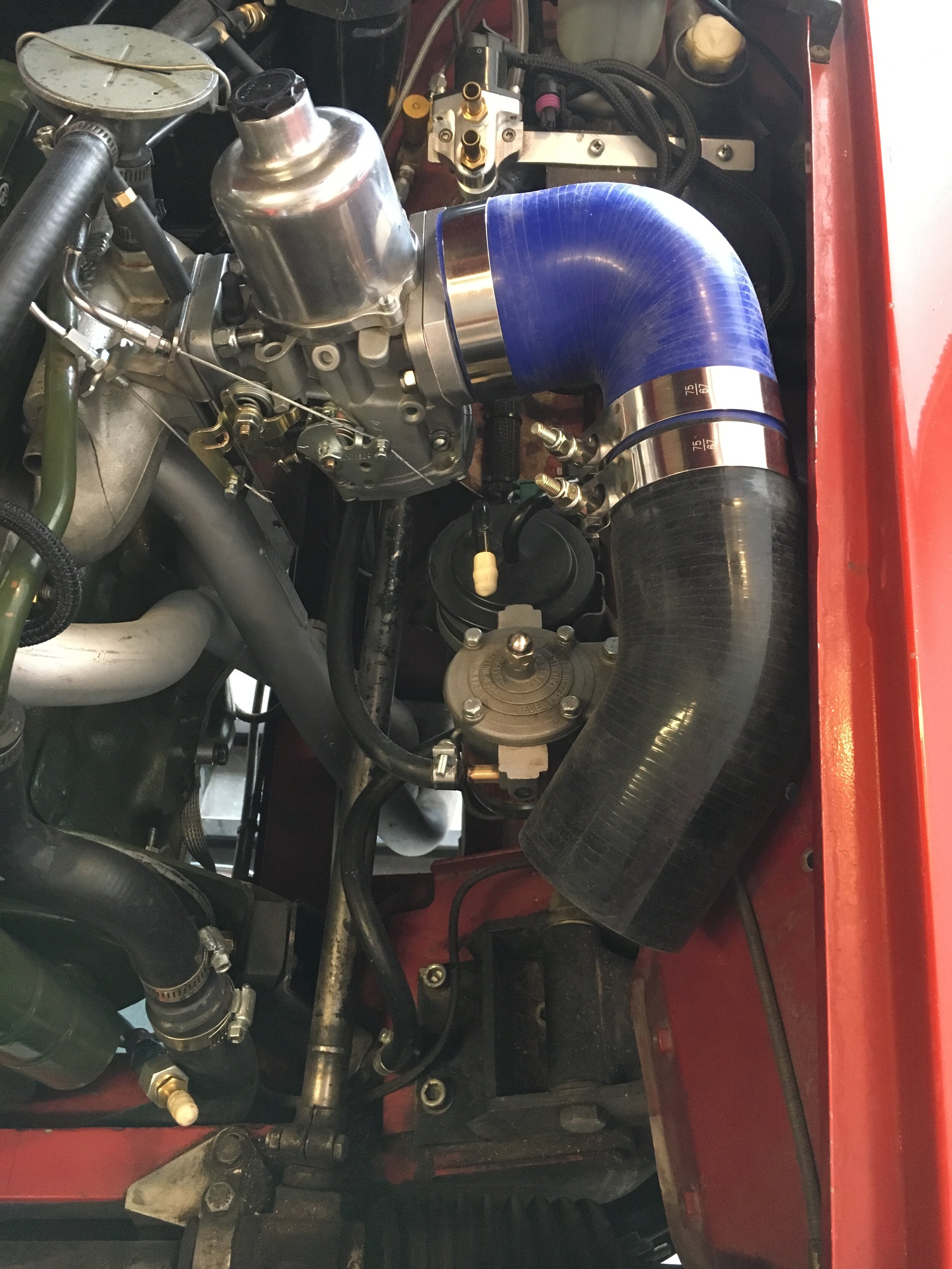
Third, rotate the 45-degree elbow so that its inlet: (i) lies against the wheelhouse, or within a finger’s width of the sheet metal; and (ii) so that it is low enough to not interfere with the bonnet closing fully:
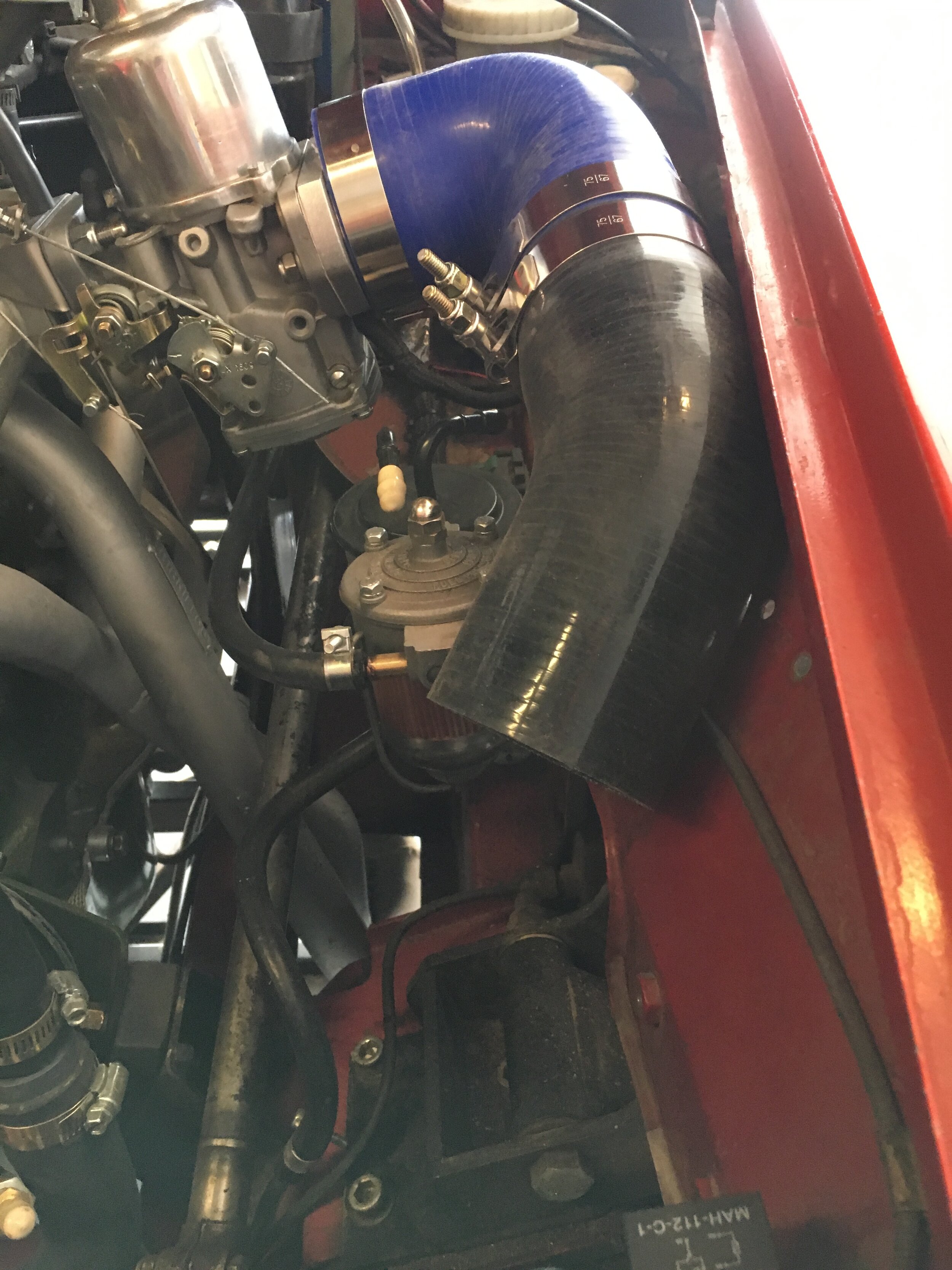
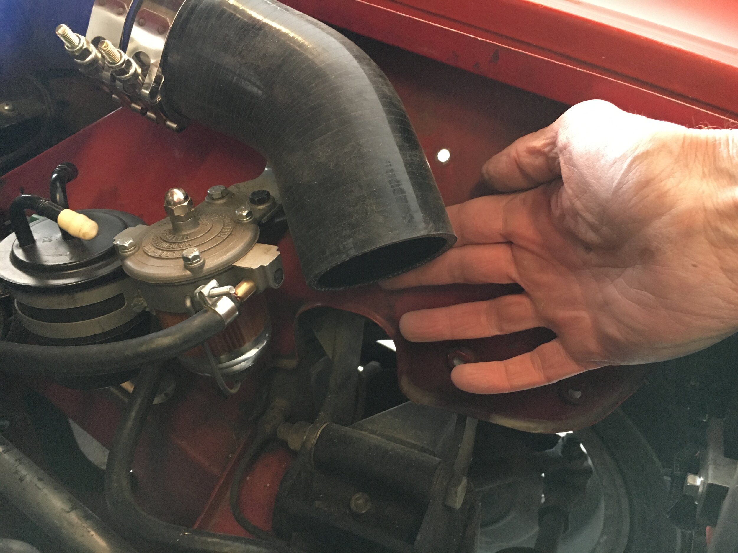
Note: the above sequence shows a low-profile regulator similar to the Metro Turbo unit, but the author’s car as seen elsewhere in these instructions features the universal Aeromotive regulator which is much taller.
Either way, when drilling the hole for your regulator’s mounting bracket, take care not to position it too high, lifting the snorkel and steel clamps into the sharp edge of the bonnet and causing misalignment with the fender or wing:

Fourth, locate the bypass valve circuit assembly (see the following section for details) and install it so that its inlet fits between the radiator and wheelhouse.
Rotate the 45-degree elbow so that with light pressure the end of the assembly will aim outboard sufficiently to clear the radiator without fouling the wheel when turned full-lock to the right when mated to the final pair of 90-degree 2” elbows that connect to the intercooler’s outlet (discussed in a moment):
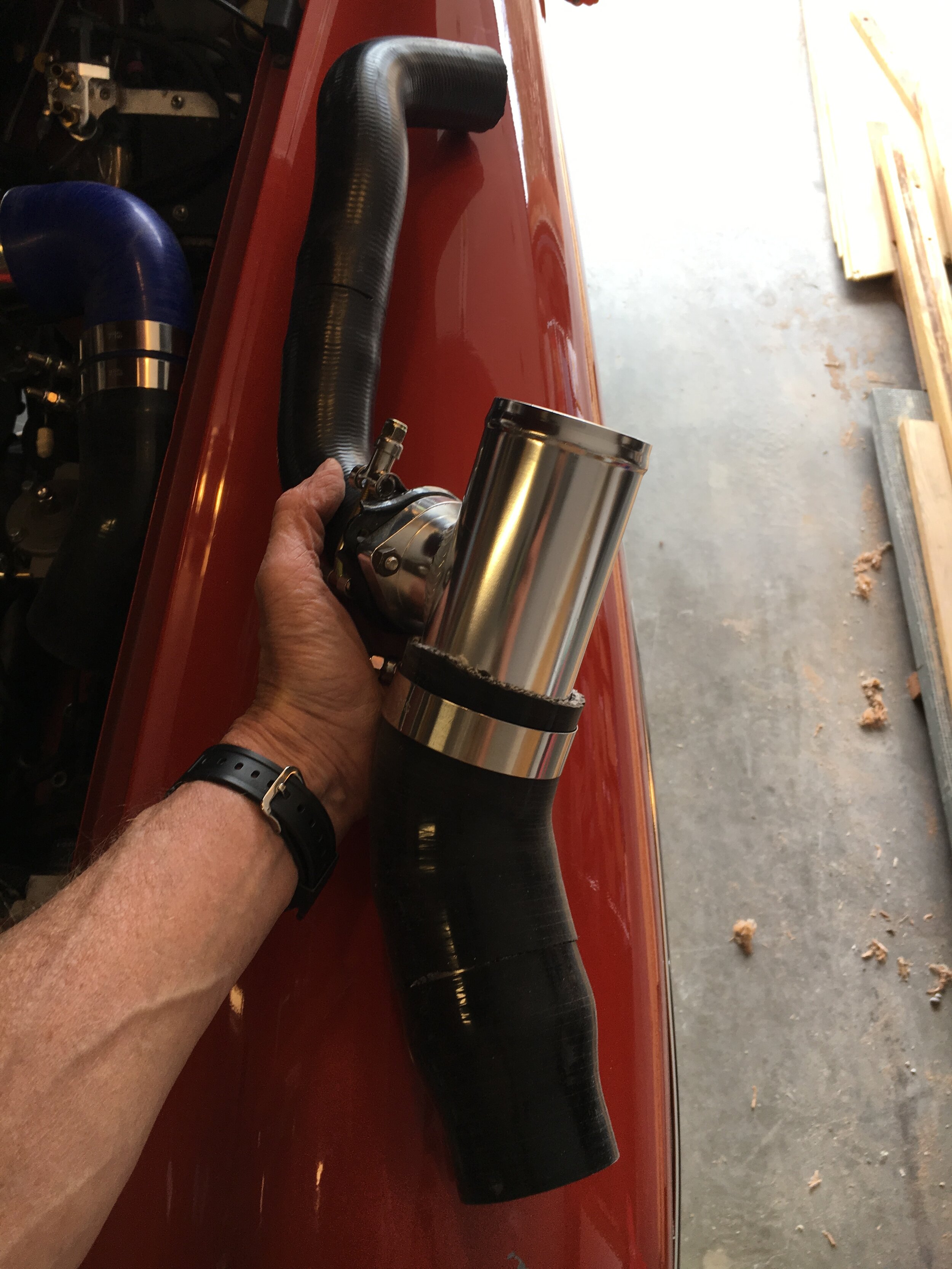
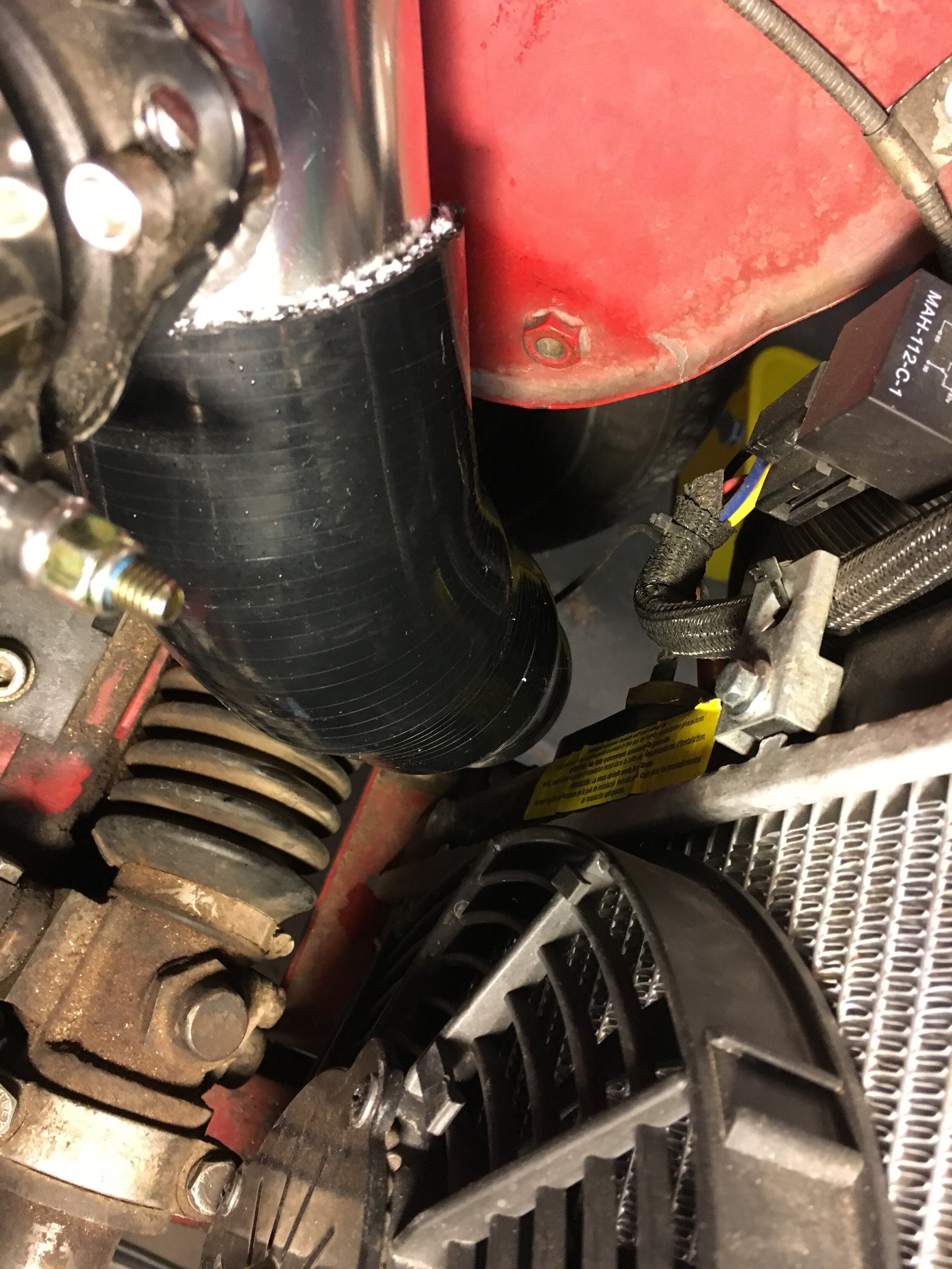
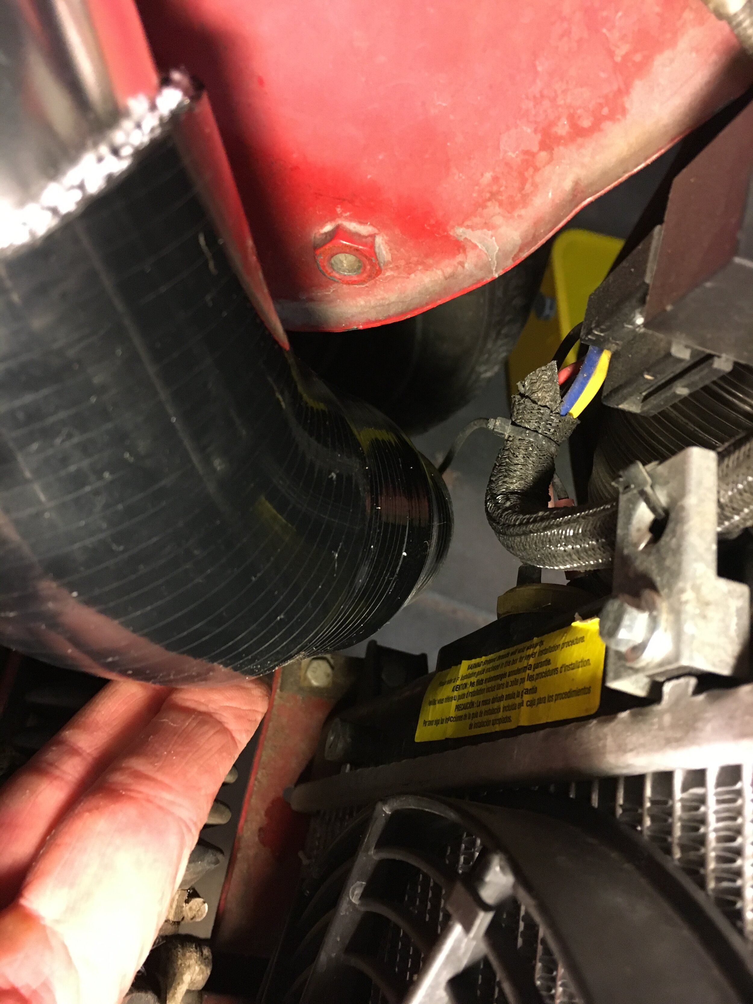
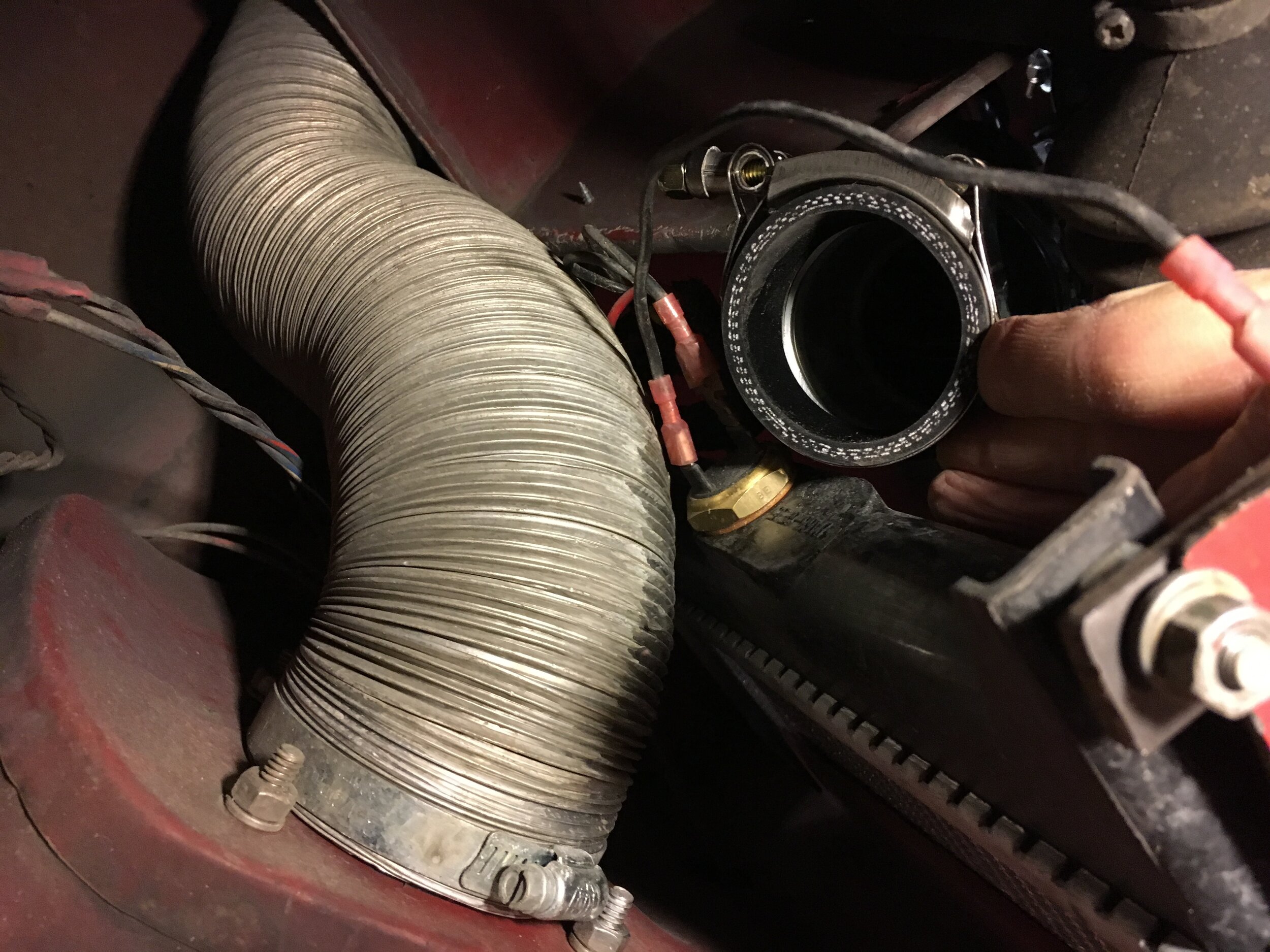
Note that there are three options at this stage of the installation: (i) the angled sheet metal may be removed—as in the photo series above, because the ‘67 Midget test mule is fitted with a VW Rabbit radiator conversion; (ii) you may cut an opening in the panel to accommodate the snorkel; or (iii) you may route the snorkel down under the bottom of the sheet metal.
Fifth, find two 90-degree 2” silicone elbows and insert a 2” aluminum nipple into one end of an elbow. Once trimmed to length, this elbow will connect the inlet of the bypass circuit assembly you just installed with the second elbow, which will attach to the intercooler’s outlet:
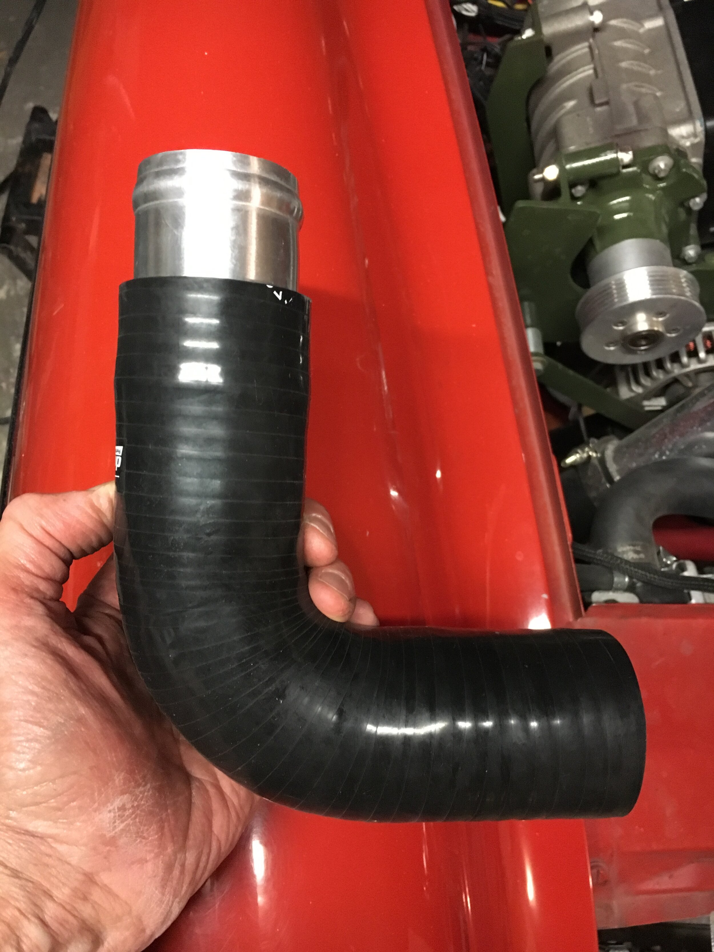
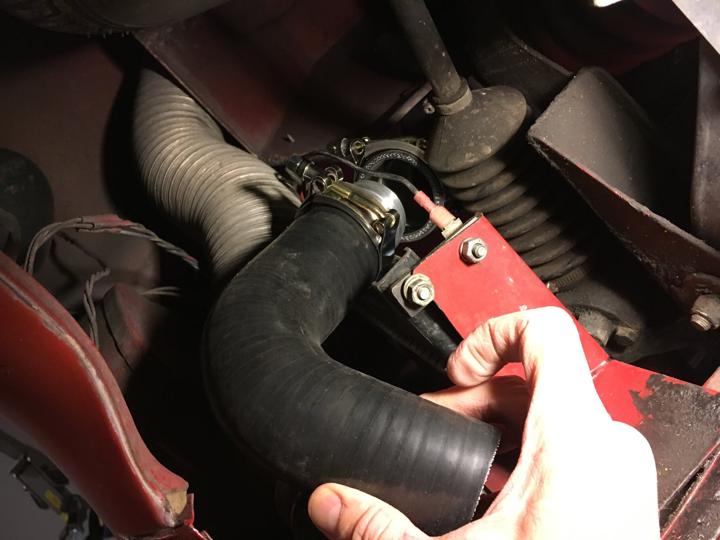
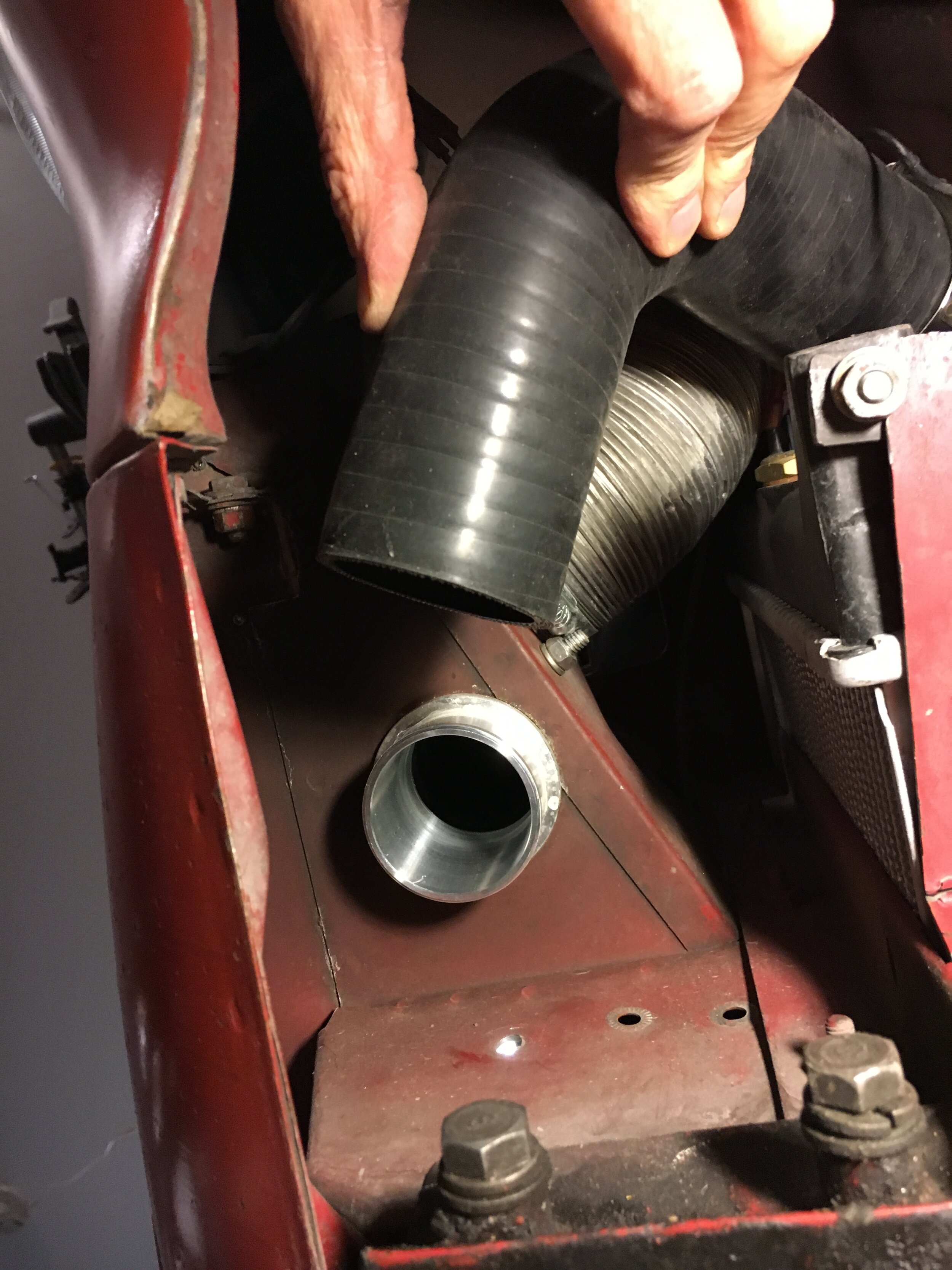
Depending on its initial size, you may have to cut 1” from the lower leg of one 90-degree 2” elbow—which connects to the bypass circuit as in the above sequence. The first photo in the next series shows the misalignment you will attempt to correct.
The second 90-degree 2” elbow will have to be cut down so that both legs are roughly 2” before connecting it to the intercooler outlet:
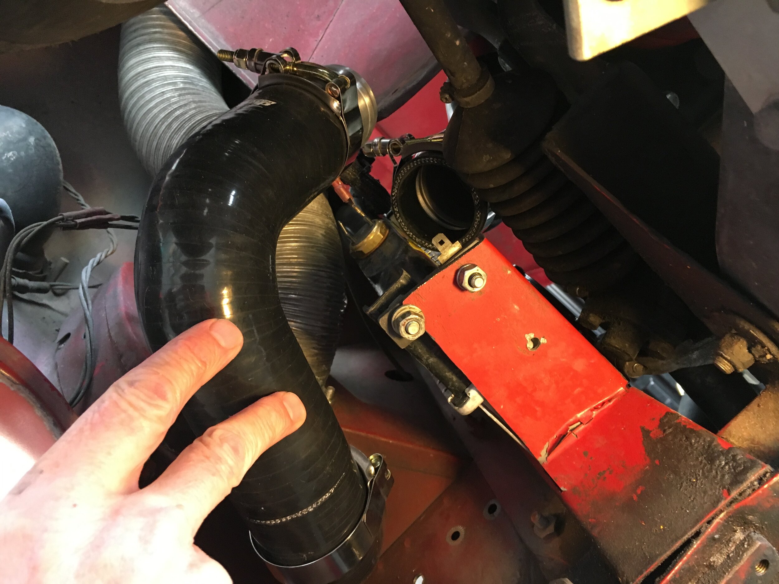
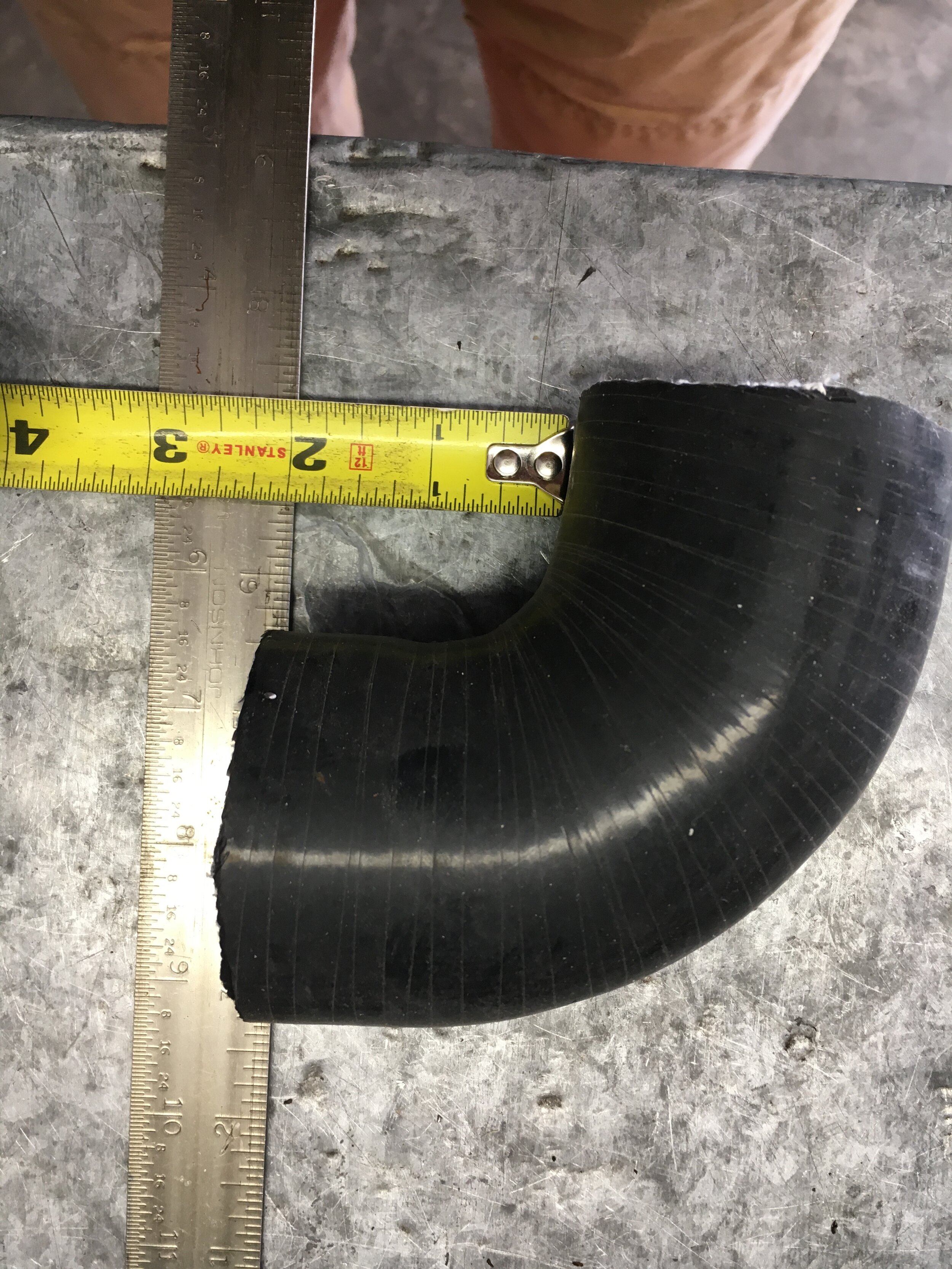
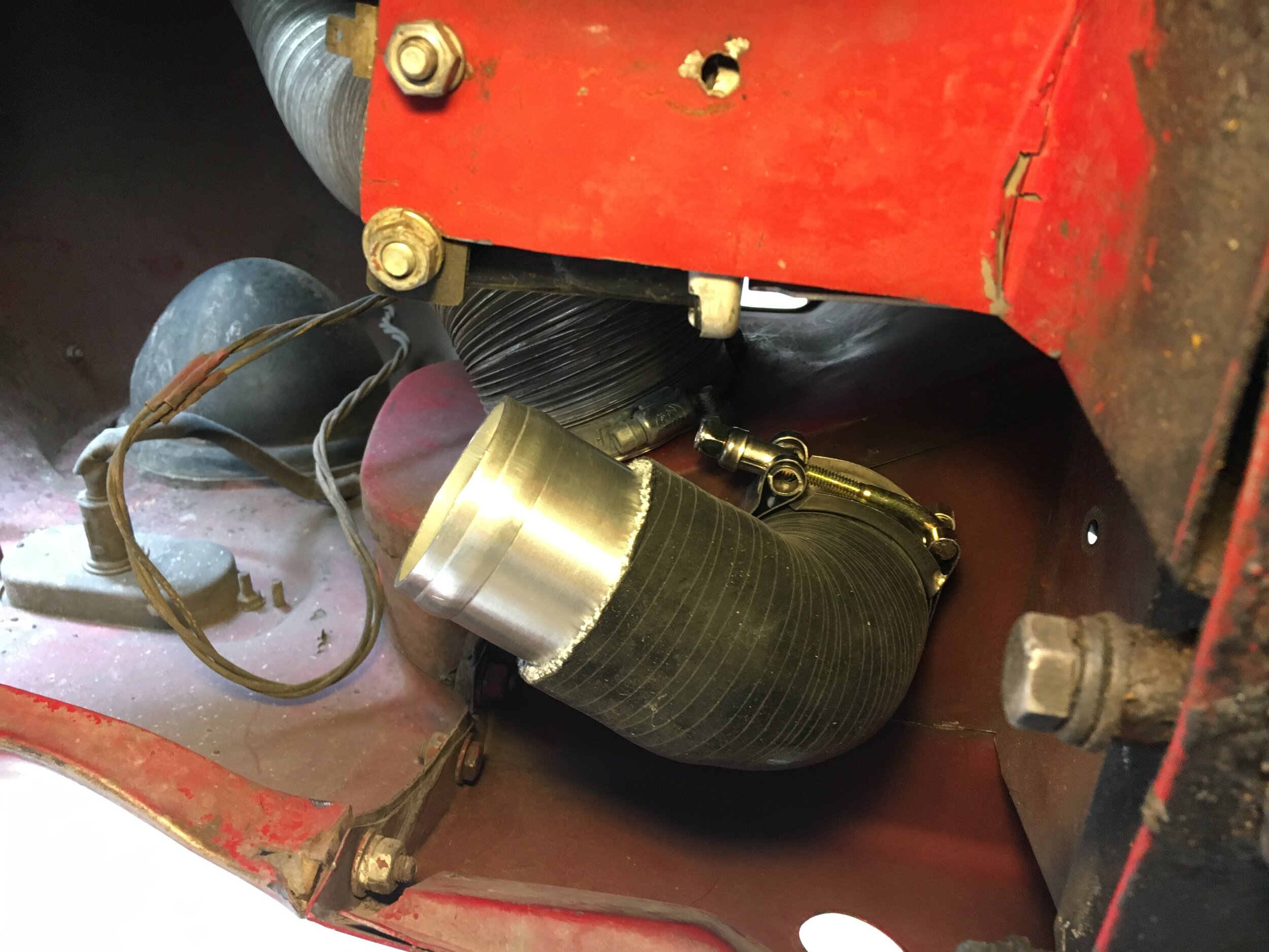
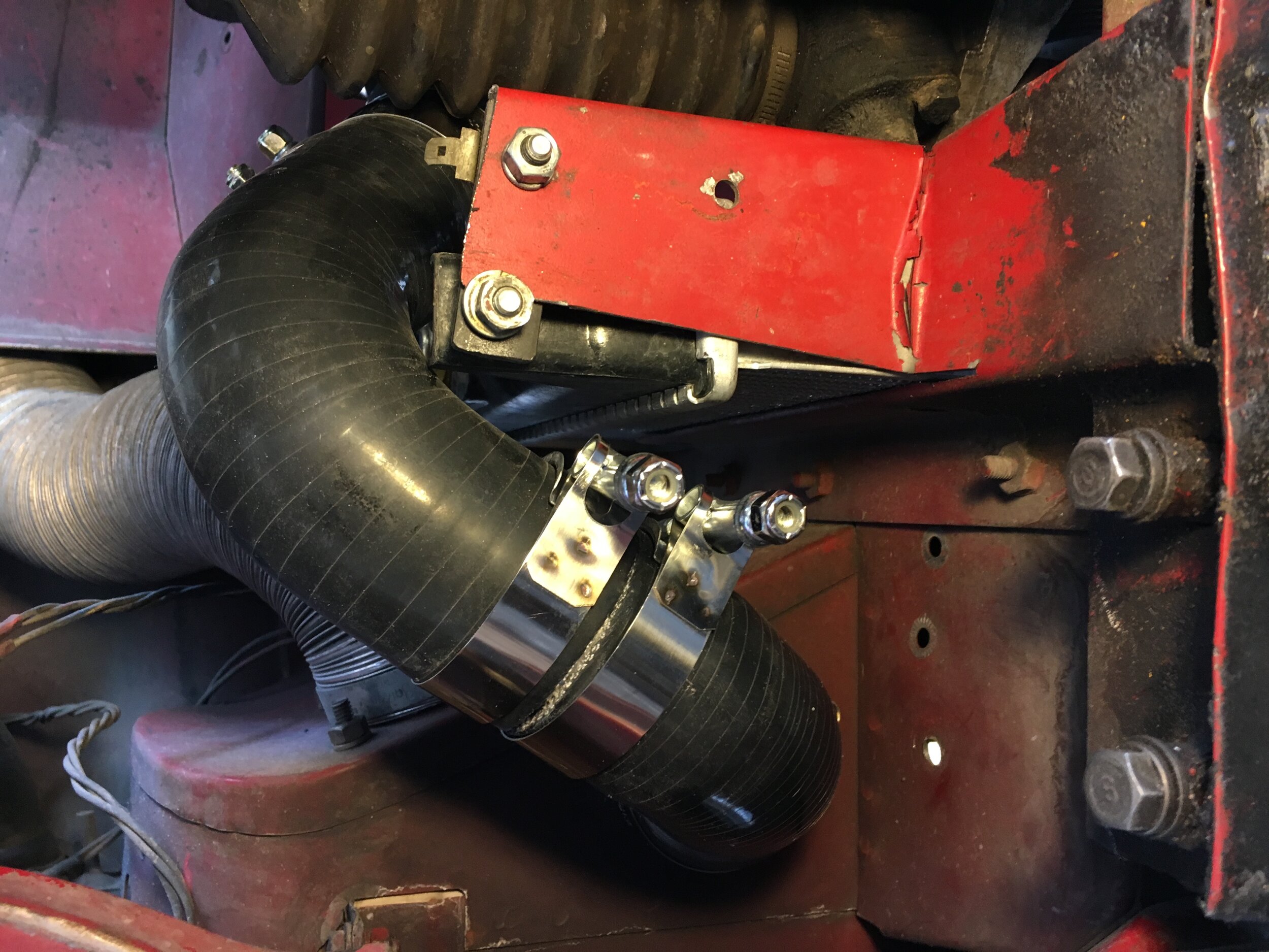
Your goal is to maintain clearance in three areas—and note that the routing probably will not need to be as precise if you are not running the relatively wide VW Rabbit radiator shown in these photos.
First, cutting too much off the lower, horizontally oriented leg of the upper 90-degree elbow will cause the bypass circuit’s inlet to contact the radiator’s tank and mounting ear. These images show adequate clearance in these first two areas—though it may be a good idea to round the corner of the radiator’s mounting ear where it grazes the elbow’s internal radius:
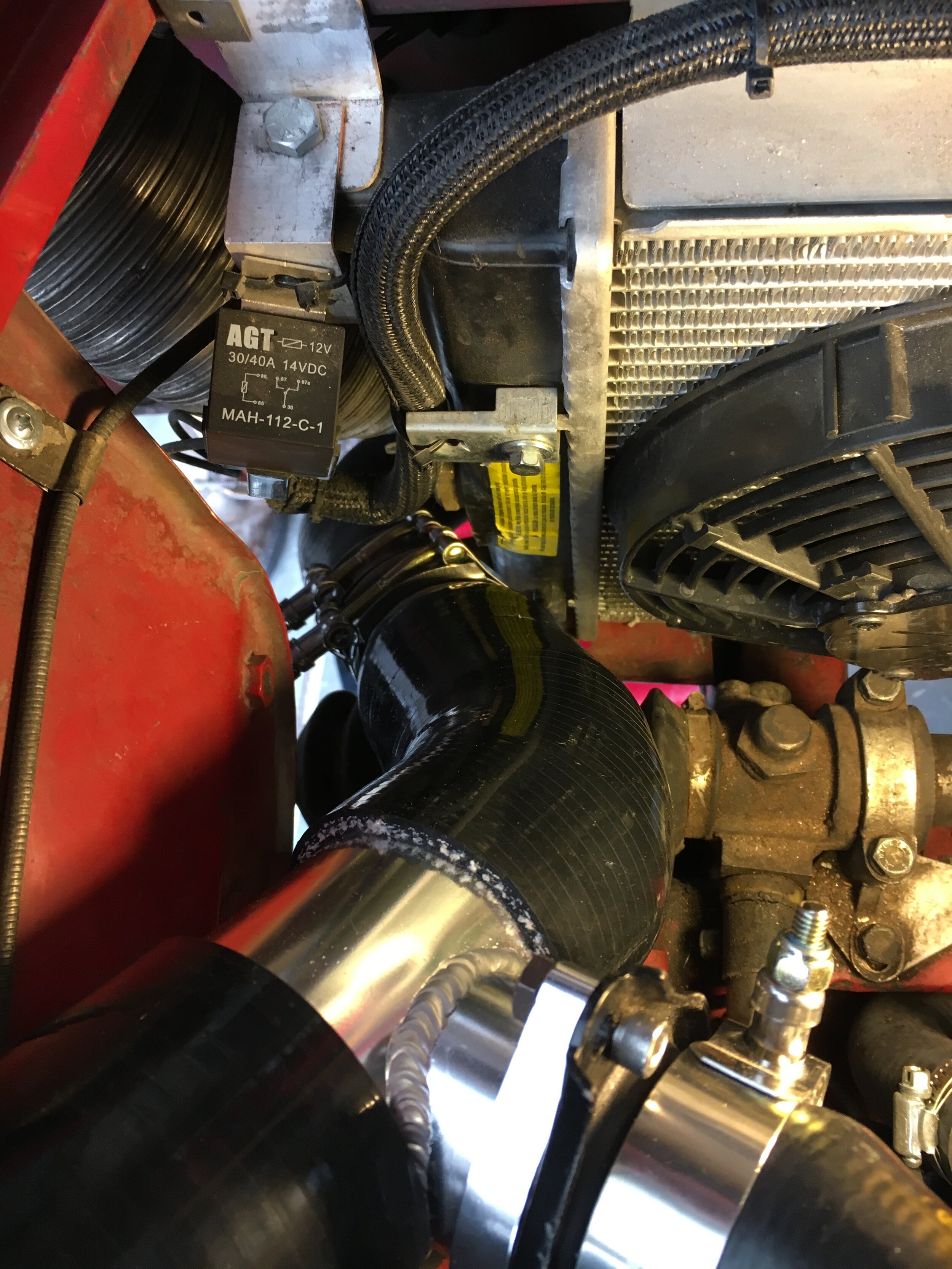
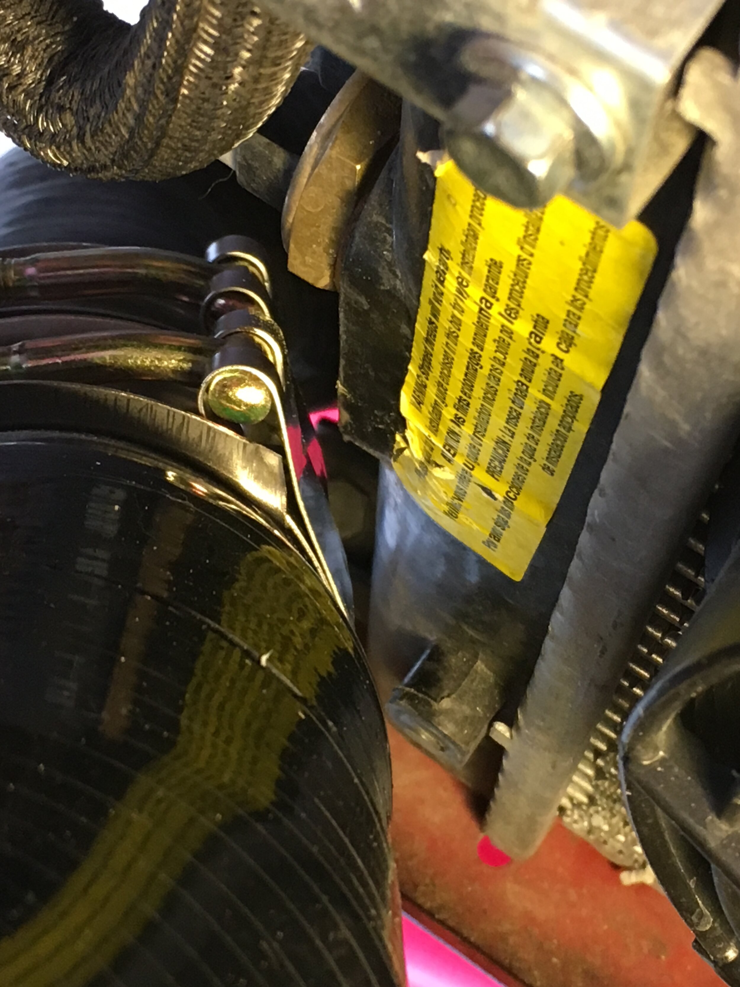
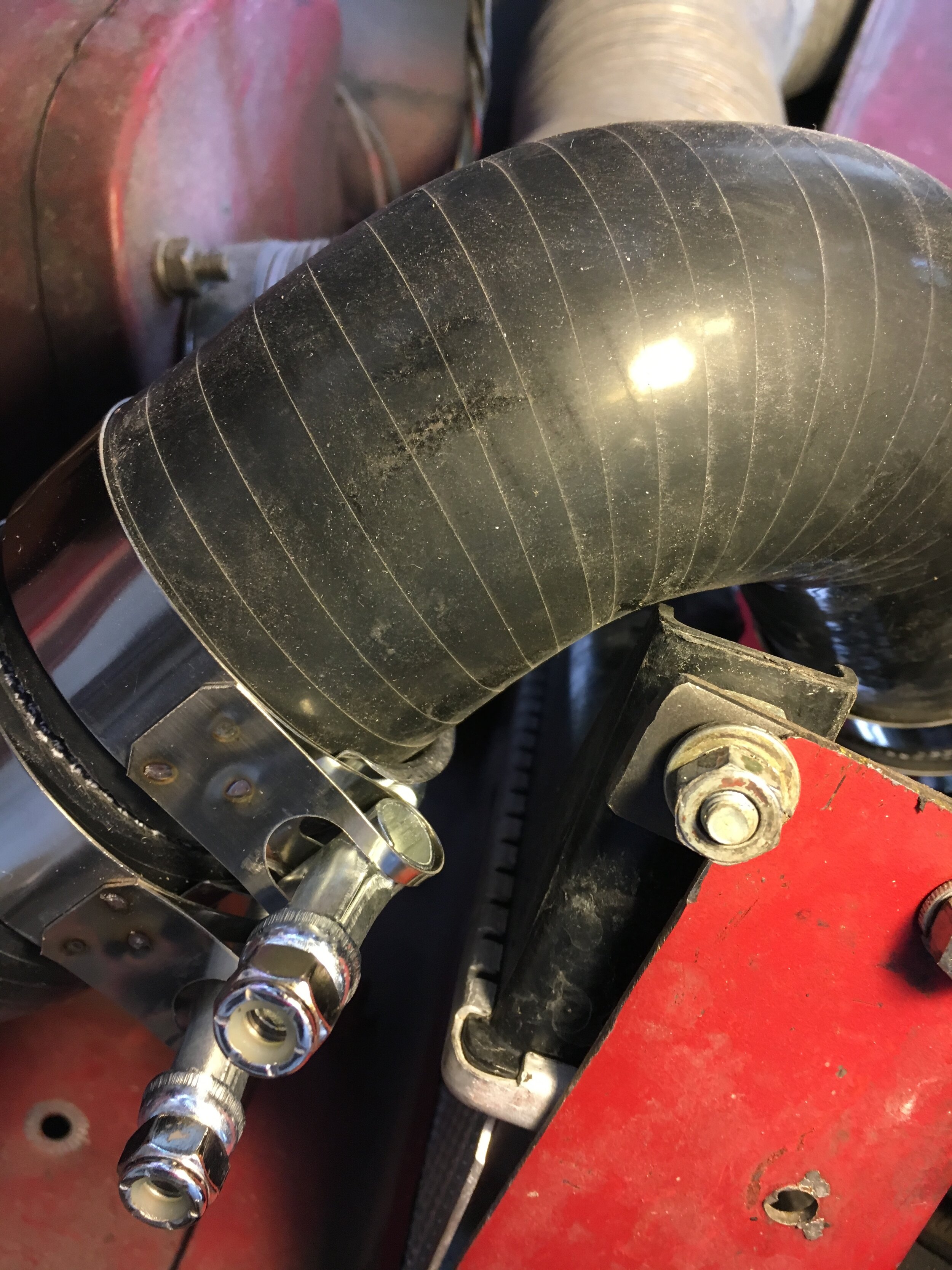
The third area of concern is the tire when turned full-lock to the right. Make sure you turn the steering wheel all the way to the right before finalizing your trimming. These images show that the clearance—at least with the VW Rabbit radiator—is around 1/8” with the car raised (first two photos), but ample when the car’s weight is on the suspension (third photo):
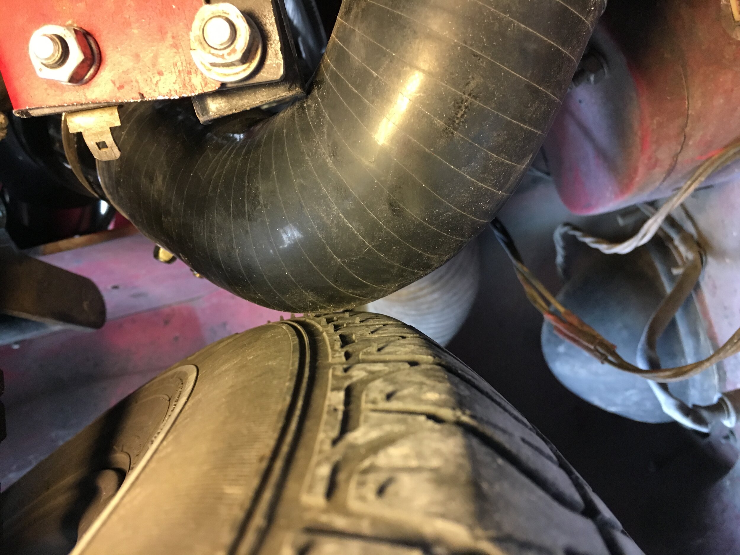
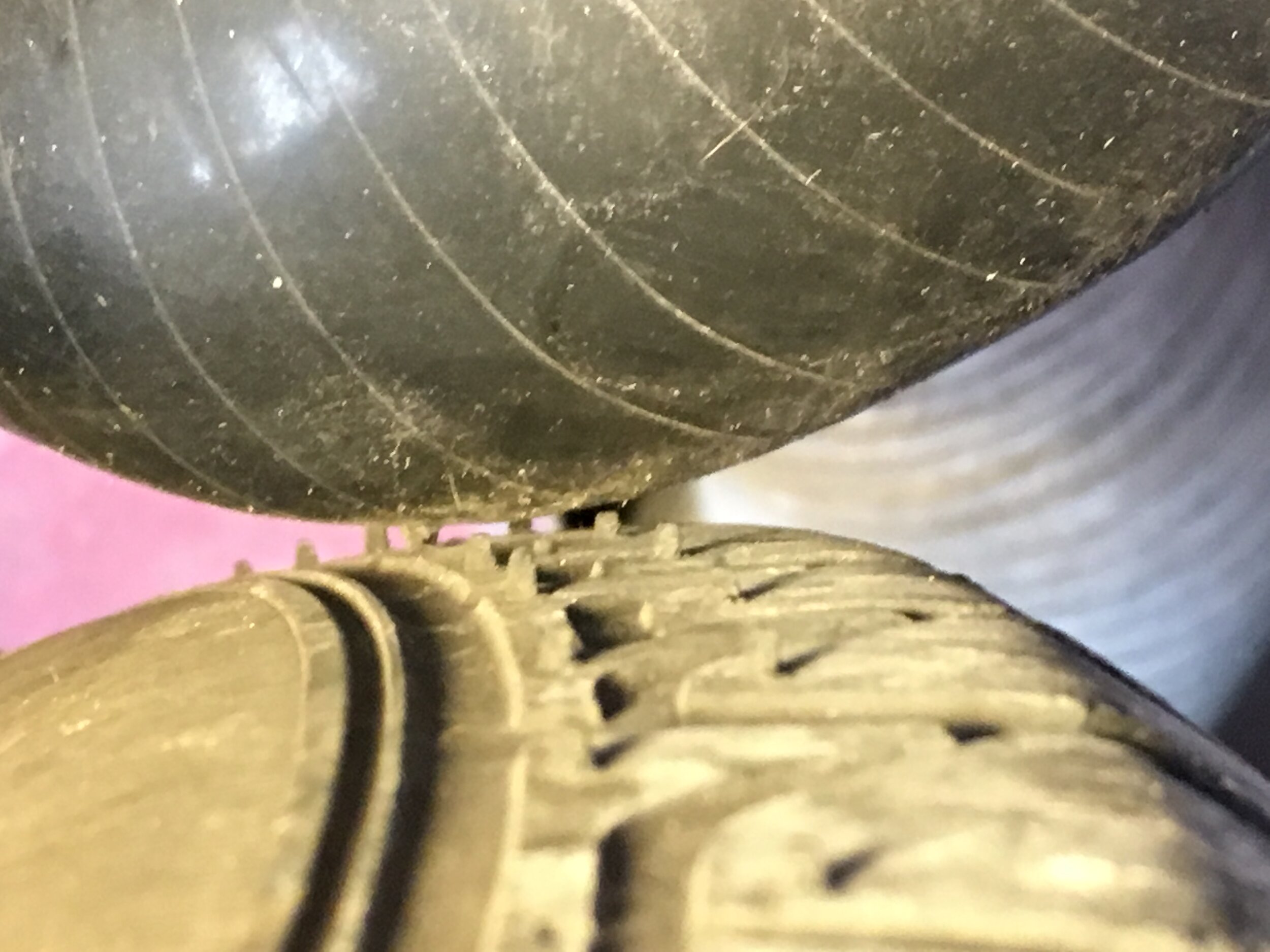
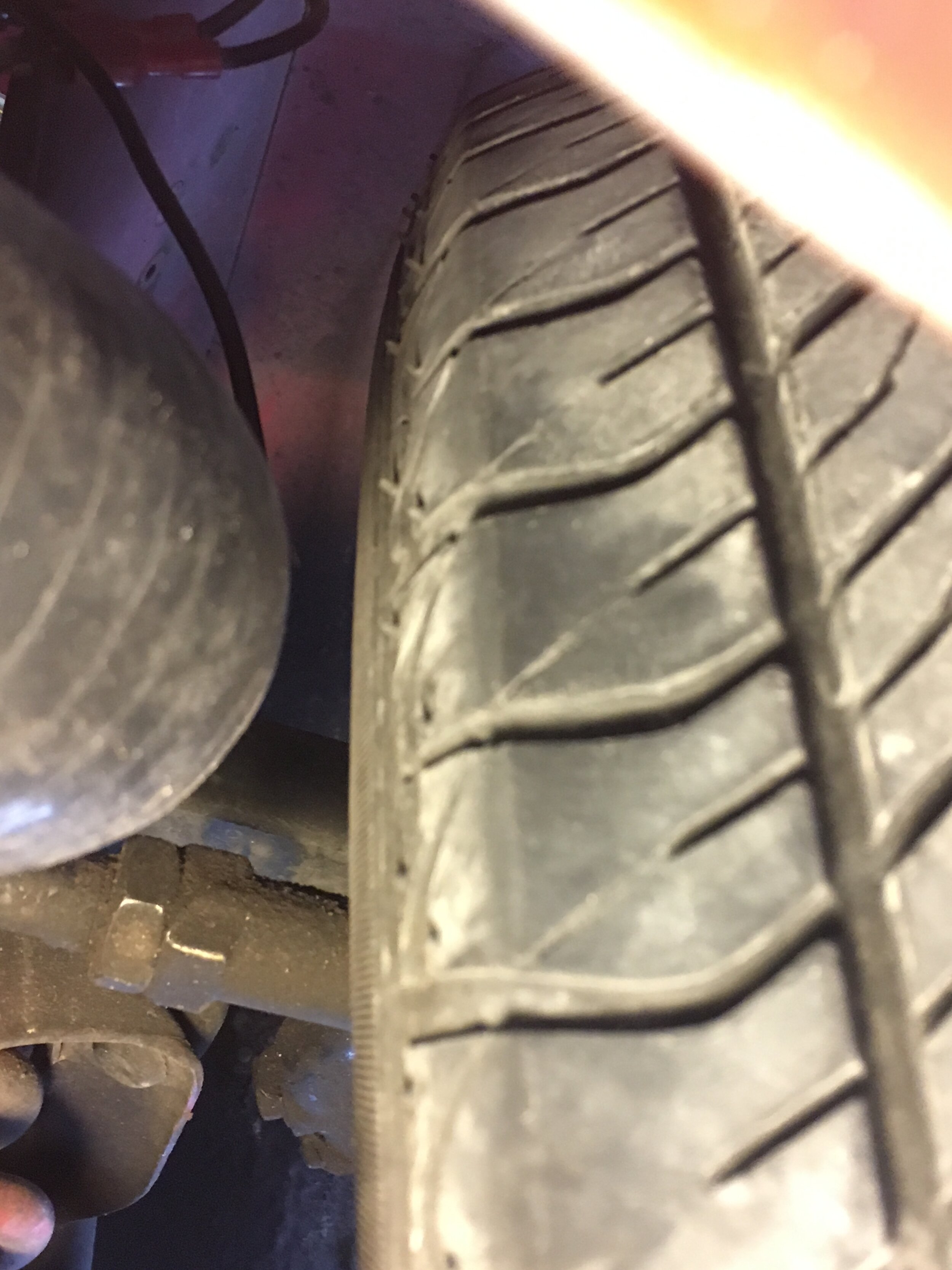
plumb the bypass circuit and intake tract
We strongly urge you to add a supercharger bypass valve. The benefits are improved fuel economy and reduced wear and tear on the supercharger and serpentine belt during trailing throttle and steady-state cruising conditions.
However, without a bypass valve, or at minimum a waste gate to vent unused boost out of the intake tract downstream of the supercharger and before the carburetor, the best-case scenario is premature wear of the blower and serpentine belt and jerky throttle transitions. The worst-case scenario is damage to snorkels, vacuum lines, and possibly the engine itself.
We recommend the bypass valve from a 2002 Mini Cooper S.
There are three minor modifications needed for this conversion: (i) remove the vacuum hose, which in the Mini Cooper S installation references vacuum from its own bore, and cap the brass nipple on the valve body; (ii) connect the diaphragm’s nipple to the metered distributor nipple on the carburetor, as shown below (insert a Tee fitting in the hose if you wish to retain vacuum advance); and (iii) replace the OEM diaphragm spring with a lighter version (included with the bypass valve adapter used in this conversion).
*Note: you may experiment with connecting the bypass valve’s diaphragm to manifold vacuum for more responsive actuation. We found the drivability was improved by using metered vacuum as shown below:

There are several possible routes for the bypass circuit, depending on he vehicle your are supercharging.
The benefit of the two options used on the red 1967 MG Midget test mule in the photos throughout these instructions is that they place the air cleaner under the left-hand fender, where it receives cool air ducted from behind the grille.
However - it only recently occurred to us that one can entirely eliminate the snorkel connecting the bypass valve to the blower’s air inlet tract by simply placing the bypass valve ahead of the radiator support and attaching a small air filter directly to the valve’s inlet. You could leave the valve where it is, but then of course its air filter would draw heated air from the engine bay during steady state cruising.
Regardless, this exquisitely detailed Morris Minor adopts an approach similar to the ’test mule ’67 Midget, with a custom airbox housed outboard of the engine bay on he lefthand side of the car:
![image0[3] (1).jpeg](https://images.squarespace-cdn.com/content/v1/543af5a2e4b039cd17f66c87/1672421840897-B4LE7ZRWUNR4PLX3JNCW/image0%5B3%5D+%281%29.jpeg)
![image2[2] (1).jpeg](https://images.squarespace-cdn.com/content/v1/543af5a2e4b039cd17f66c87/1672422025781-CLYCWXR5IBJJTELLK9XJ/image2%5B2%5D+%281%29.jpeg)
Another alternative is used where the air cleaner is affixed directly to the supercharger’s inlet, as shown below in this well-executed MGB example:

The obvious differences in the MGB example above are: (i) it uses a custom fabricated, plenum-style intake to pressurize dual carburetors to fuel the 1800cc engine (though Moss Motors’ kit successfully uses a single HIF44); and (ii) the supercharger is canted outward rather than inward, made possible by the greater space in the MGB’s engine bay. (Obviously, the builder made his own mounts.)
The former difference is the only one that matters vis-a-vis the bypass circuit, in that the owner attached the Mini Cooper S bypass valve directly to his custom welded intake plenum.
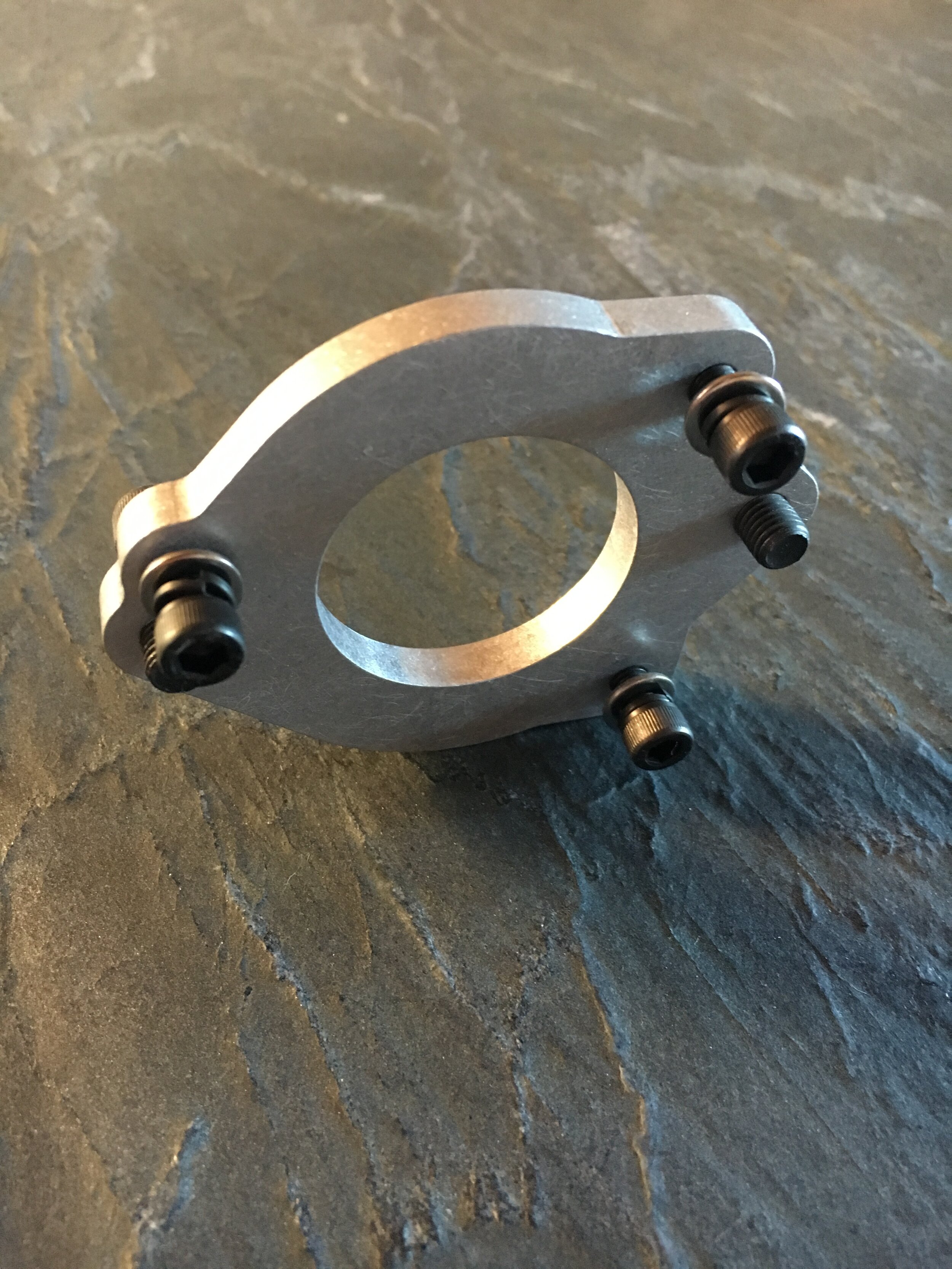
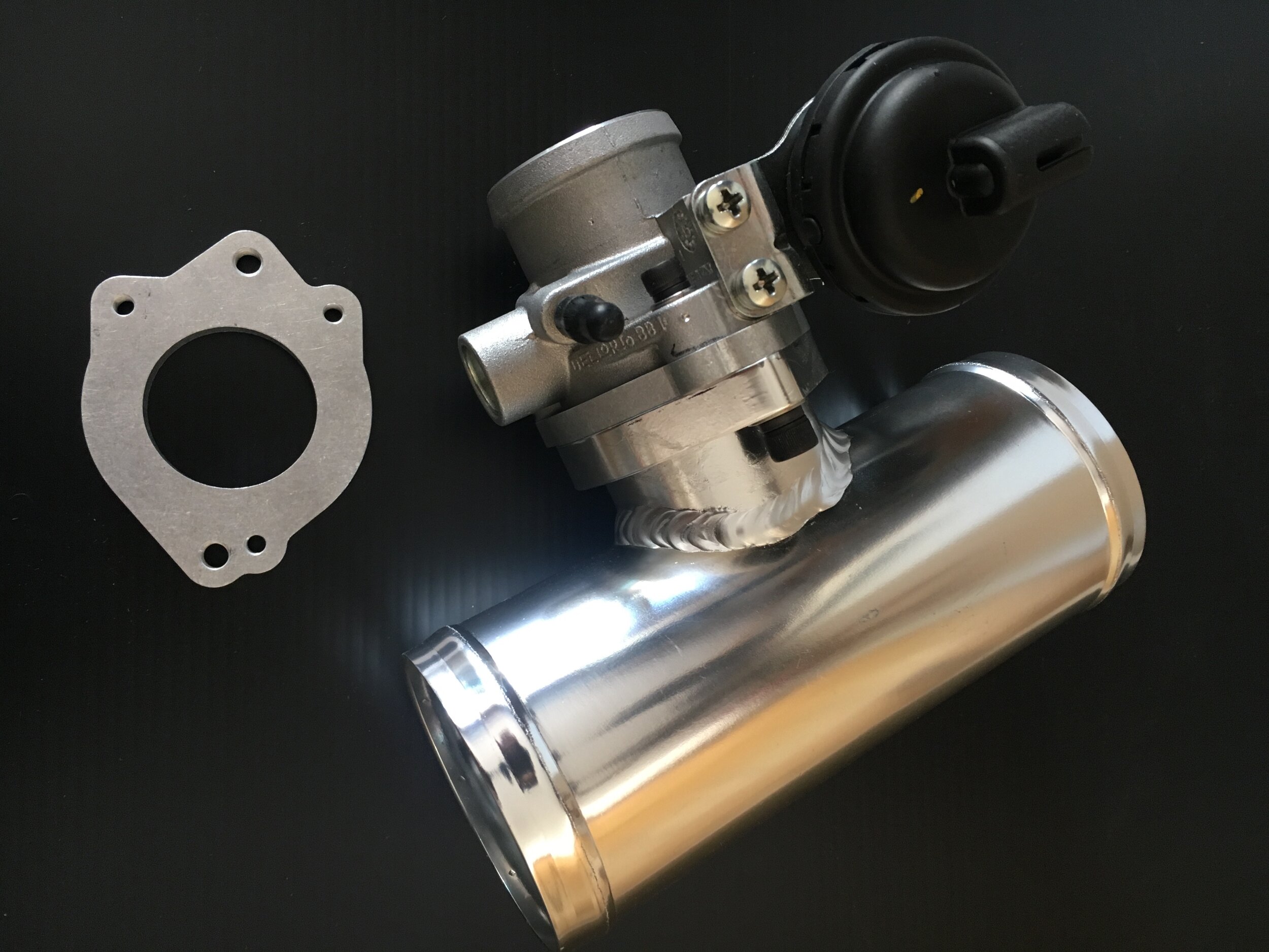
A final difference is that the MGB shown above mounts the air cleaner directly to the blower’s inlet via a short pipe that accepts the bypass circuit. This means the system is drawing hot air from within the engine bay.
Our ‘stealth’ cool air intake positions the air cleaner under the left-hand fender, where it is blasted with a 3” duct from behind the grille. Below is a diagram of the snorkels to keep you oriented as you complete this section.
*Note that in the following diagram the bypass valve is positioned at the forward end of the circuit, and in the balance of the photos in these instructions it is located at the rear end.
It does not matter which alternative you choose—but we recommend installing the valve at the forward end of the bypass circuit because doing so creates more space for reaching the jet mixture screw on the carburetor.

Here is the same bypass circuit, but routed underneath the carburetor:
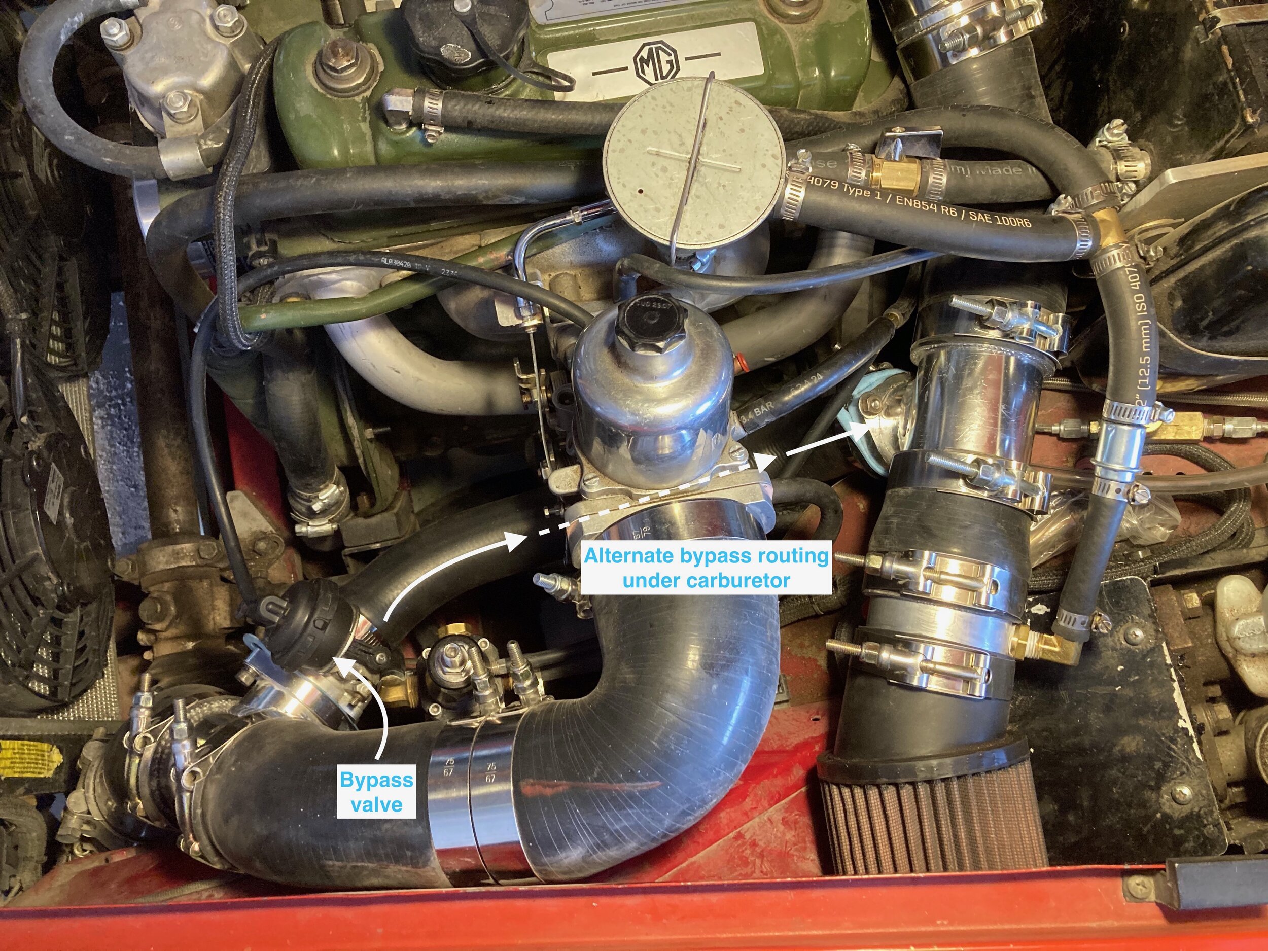
Here is yet another example, this time a Morris Minor:

Regardless of where you locate the bypass valve, you may (or may not) wish to rotate the diaphragm on the valve 180 degrees.
To accomplish this as set forth in the below slide show, first bend the steel tab retaining the diaphragm and then remove the Philips screws affixing the diaphragm to the valve body.
Next, gently insert a 1/4” or larger flat blade screwdriver in the slot formed by the diaphragm’s plastic actuation rod to release it from the valve’s butterfly linkage, and disconnect the diaphragm (it is a press fit to reinstall). Then, you simply rotate the valve to remove it from the bracket, rotate it 180 degrees, and reinstall it—with one modification required.
As you will see in the following photo series, one of the plastic tabs on the diaphragm is a different size, so you must file it (gently pushing the diaphragm’s plastic linkage to the side) to fit the bracket in the new orientation:
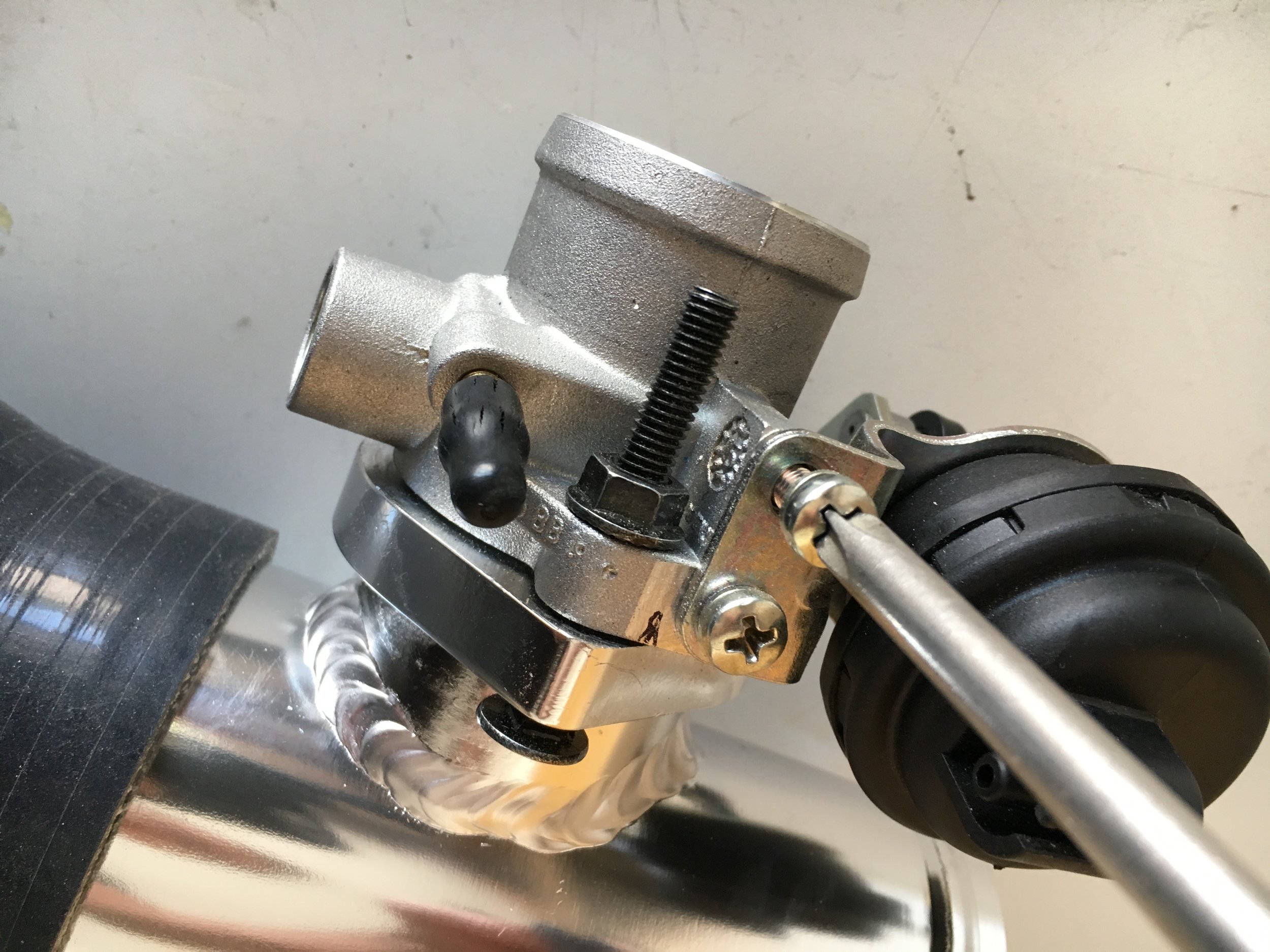
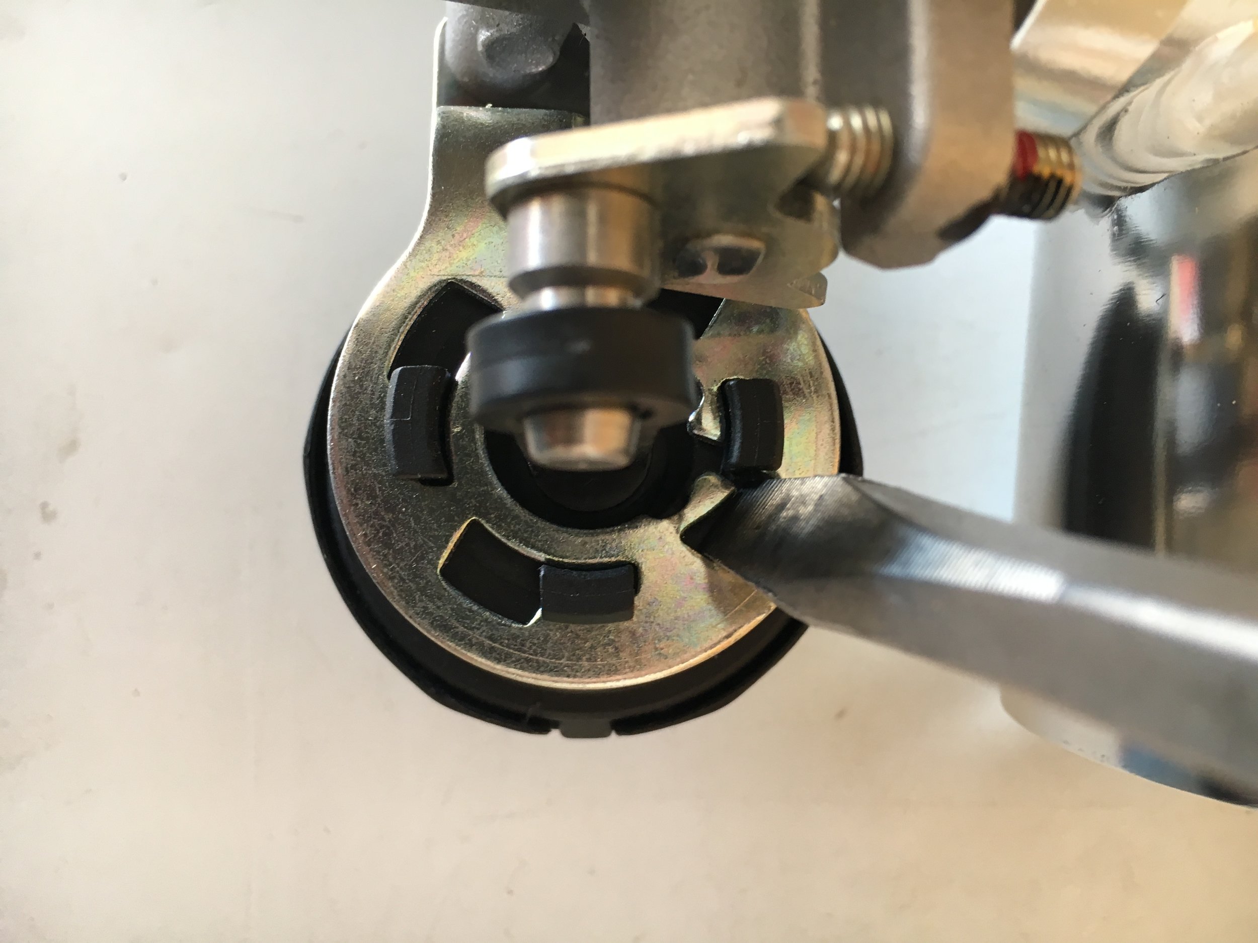
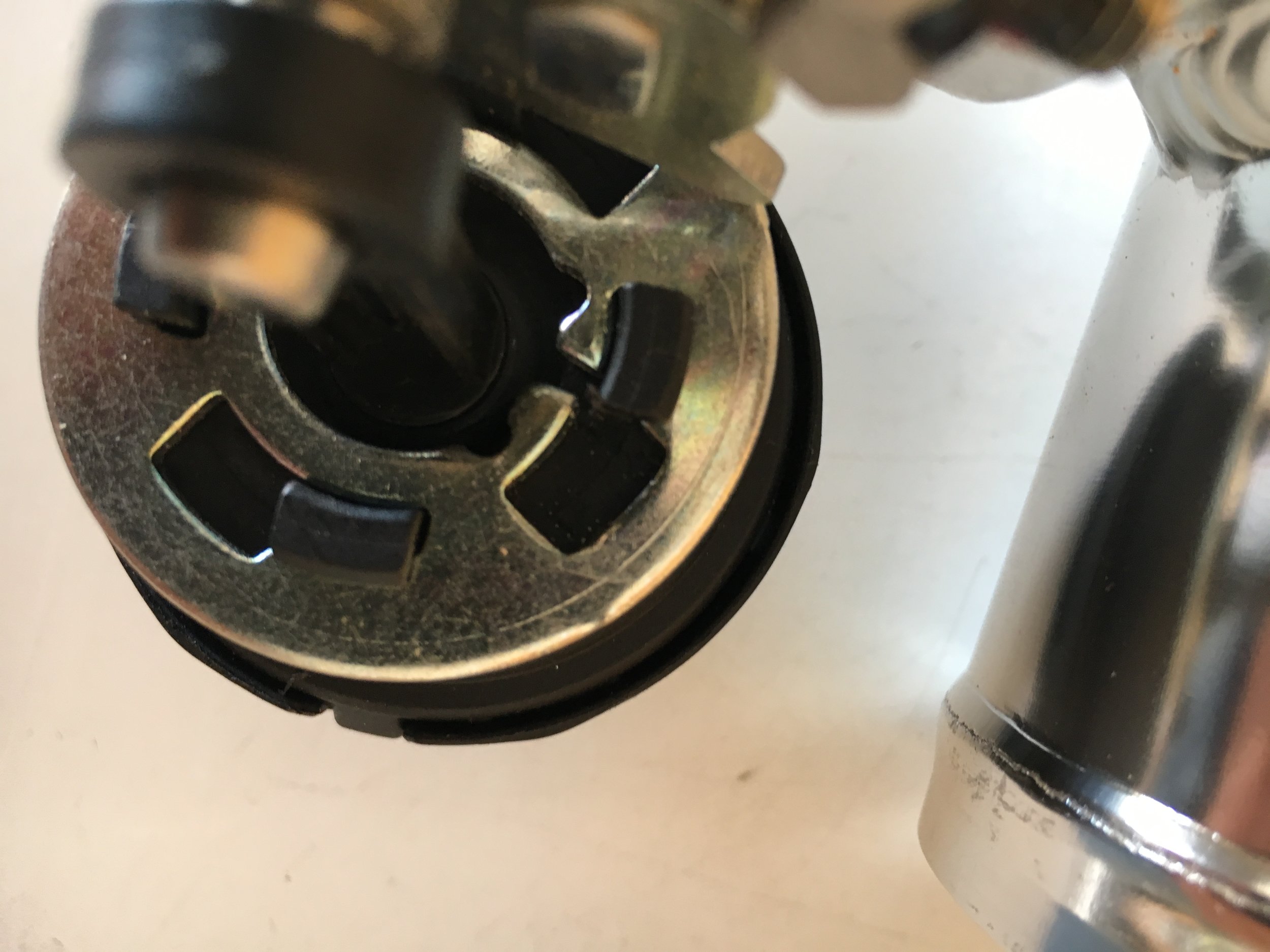
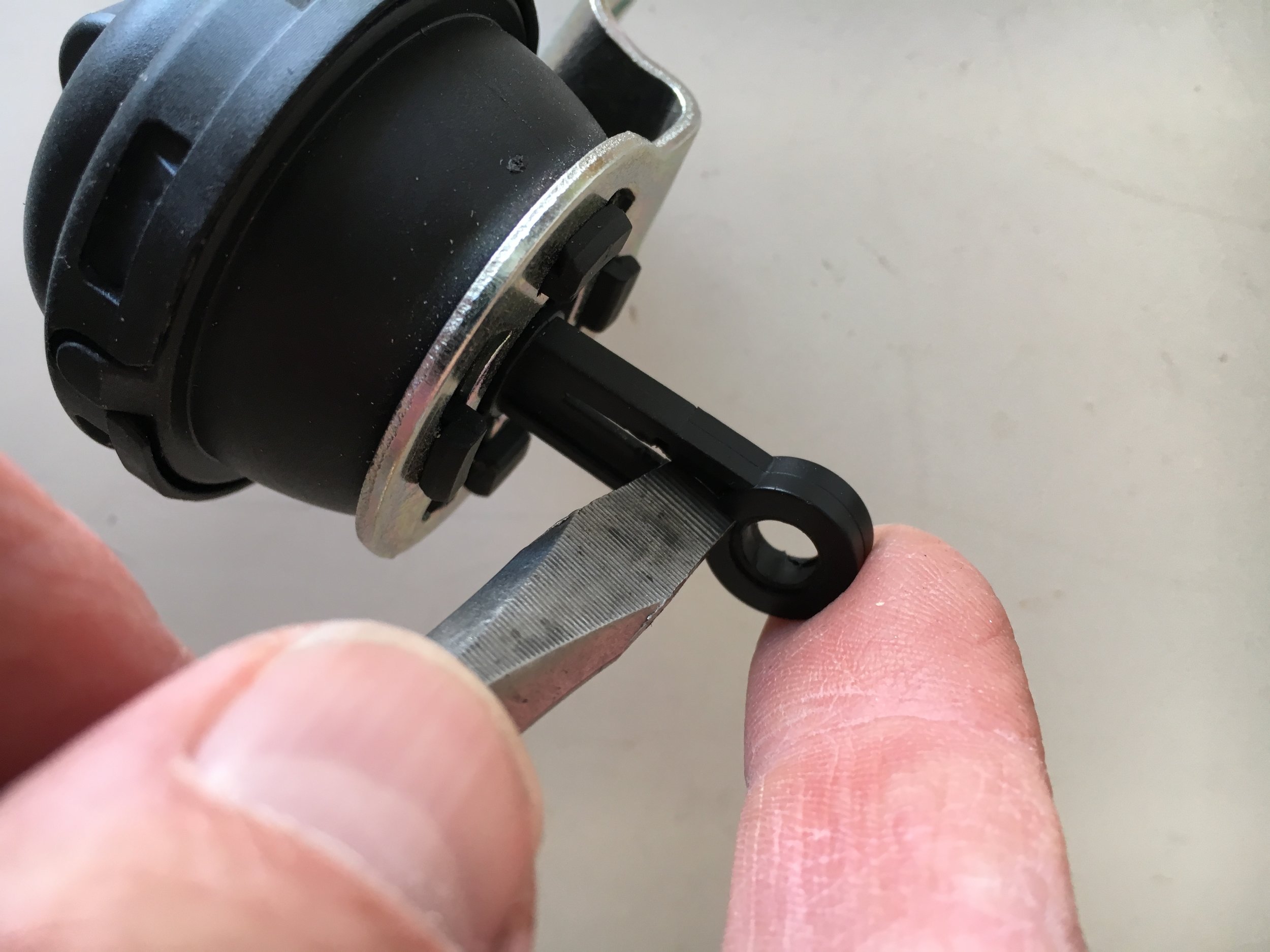
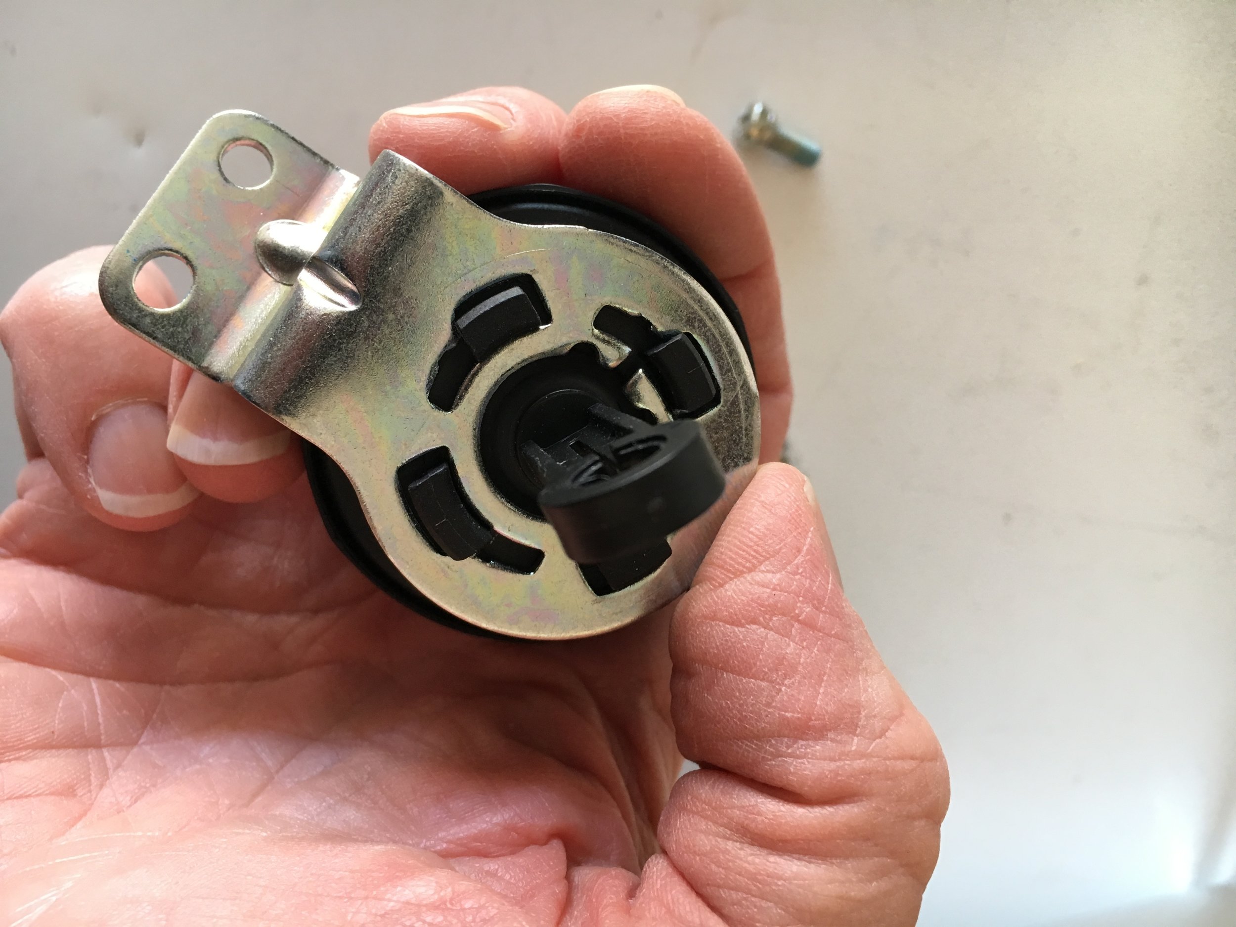
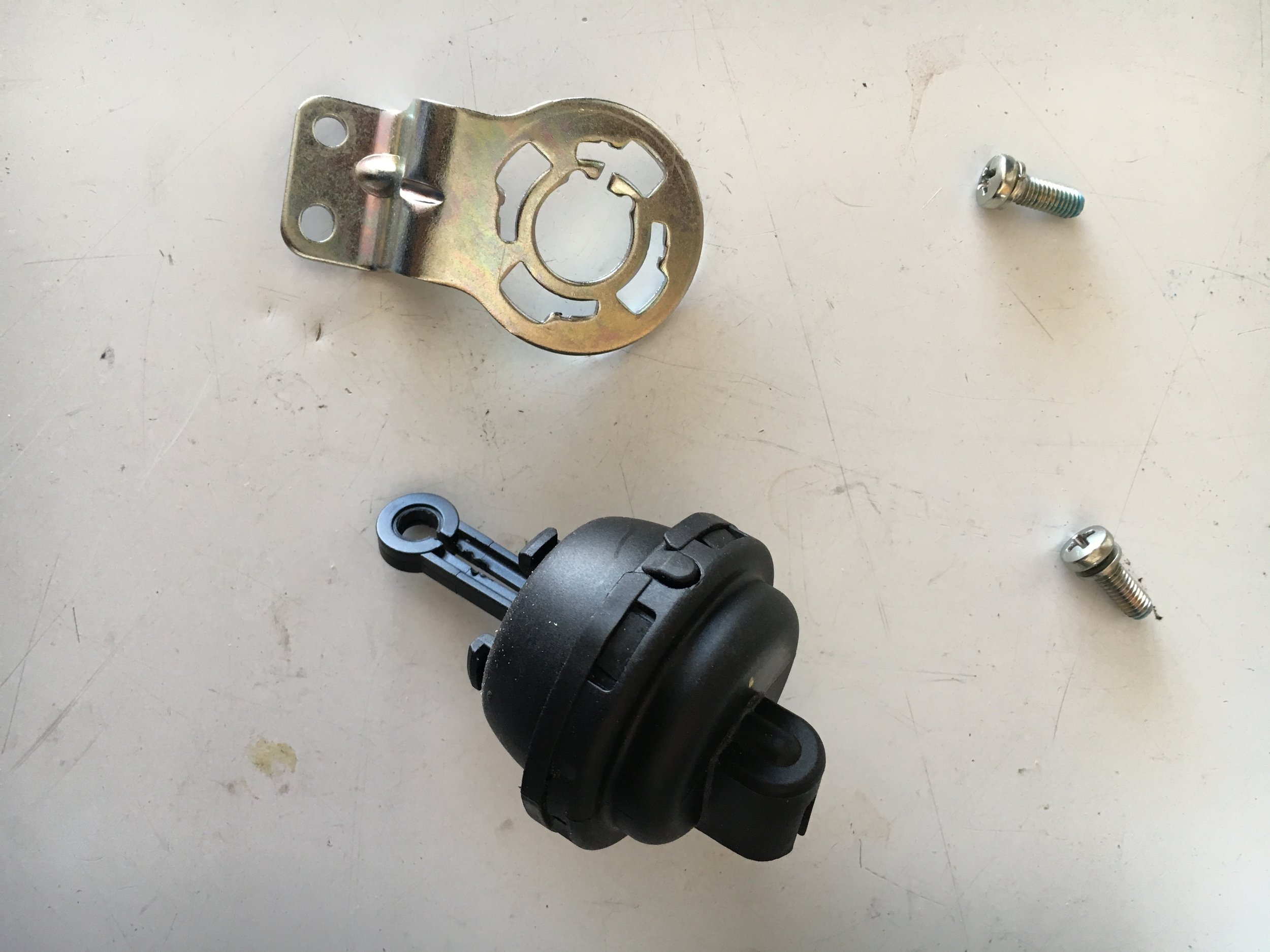
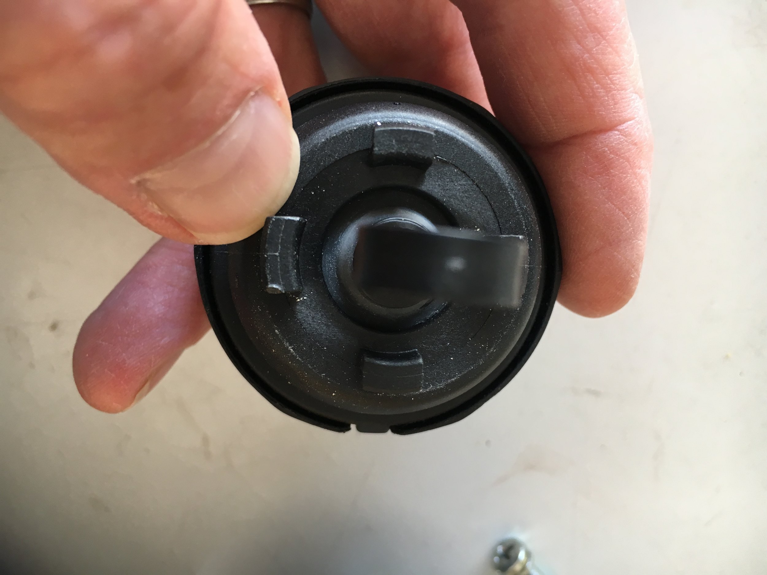
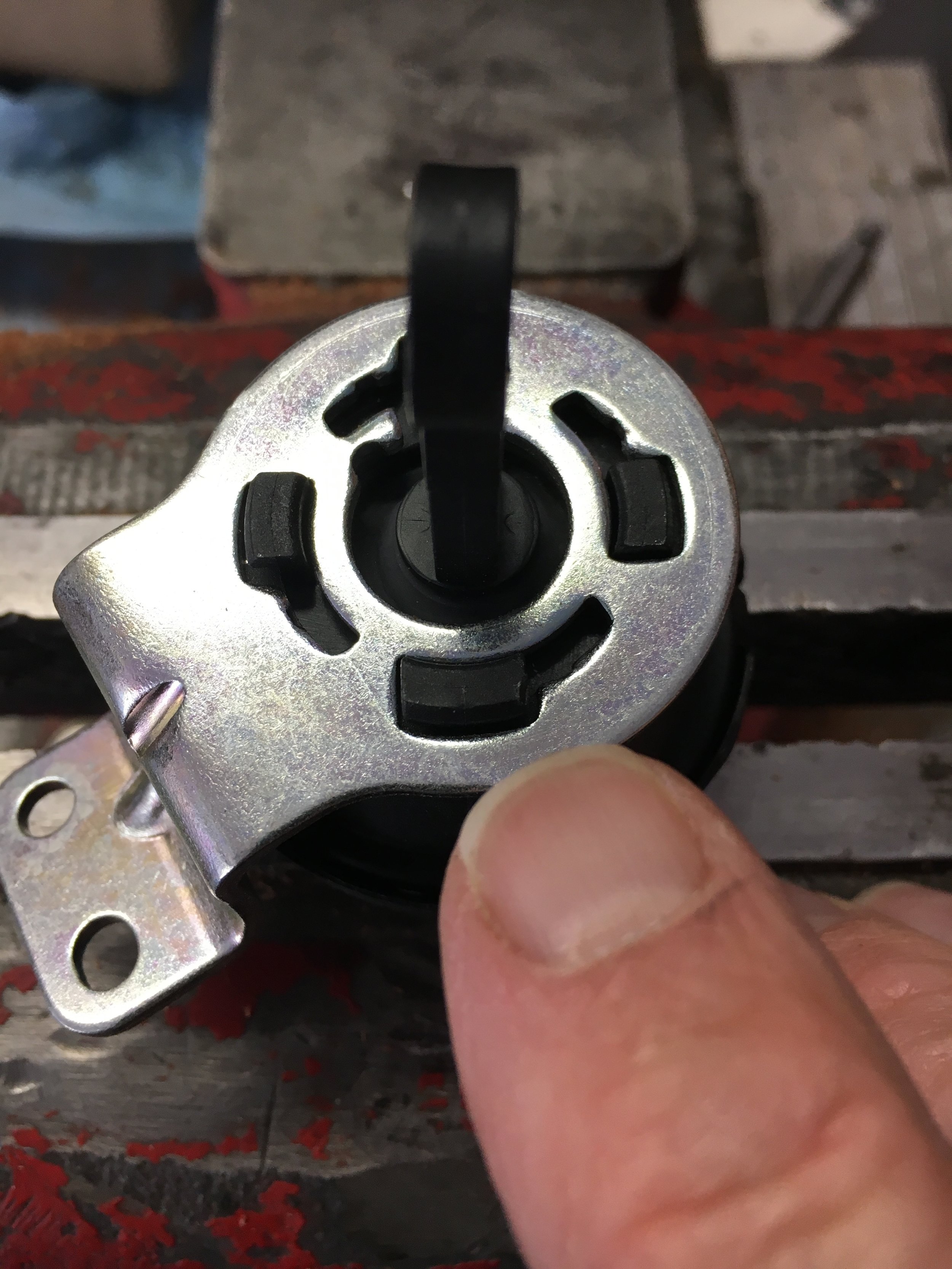
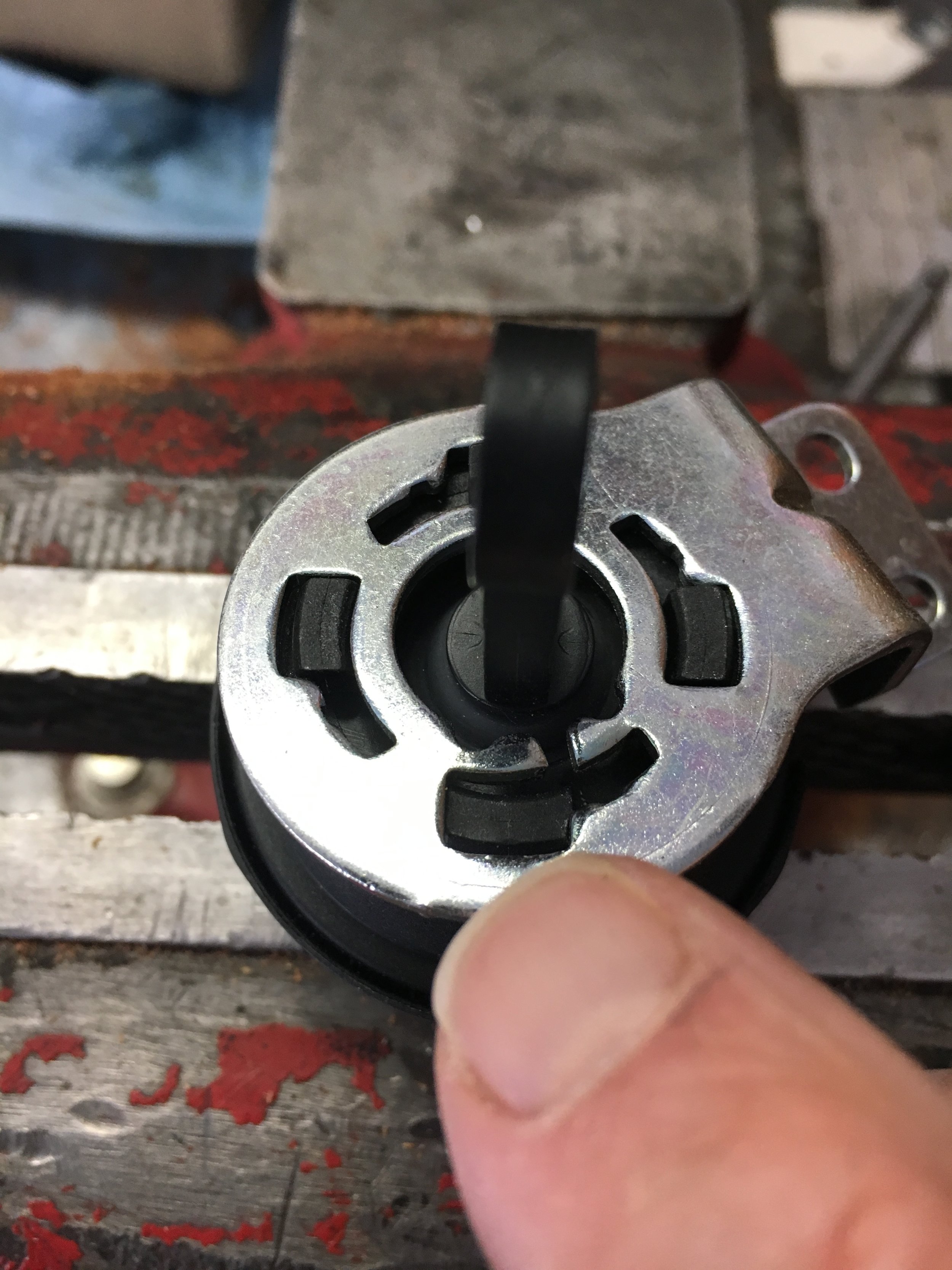
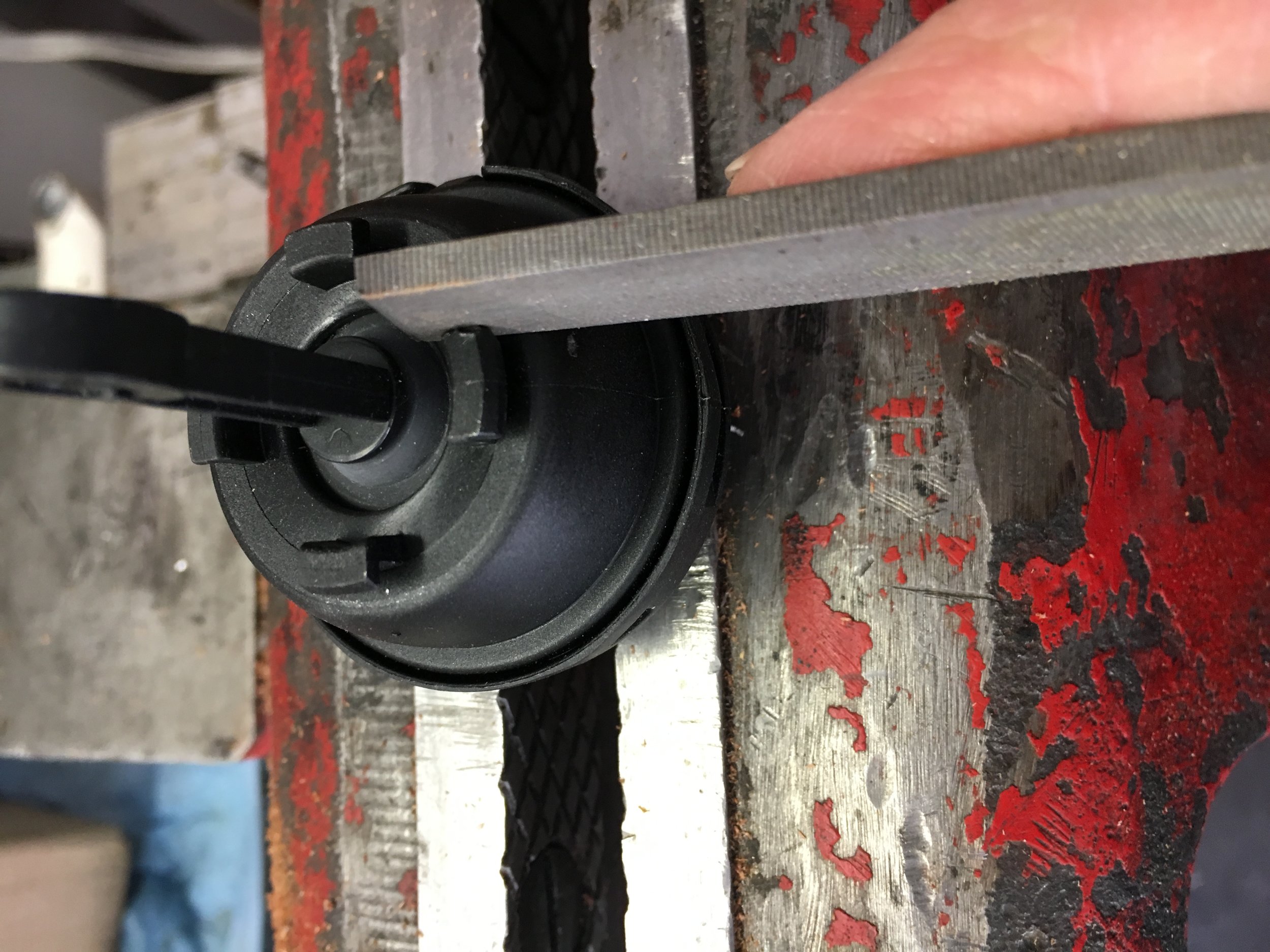
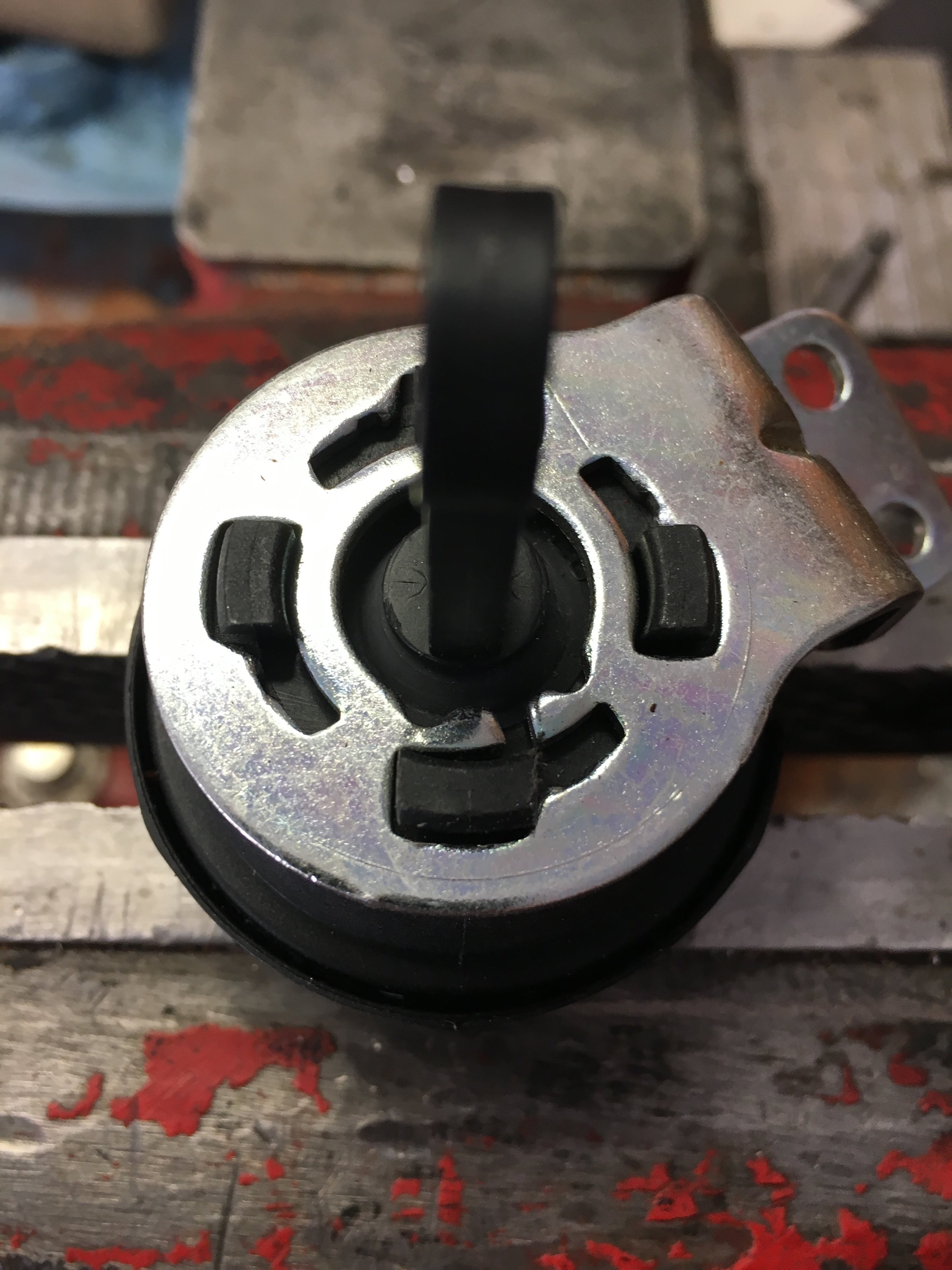
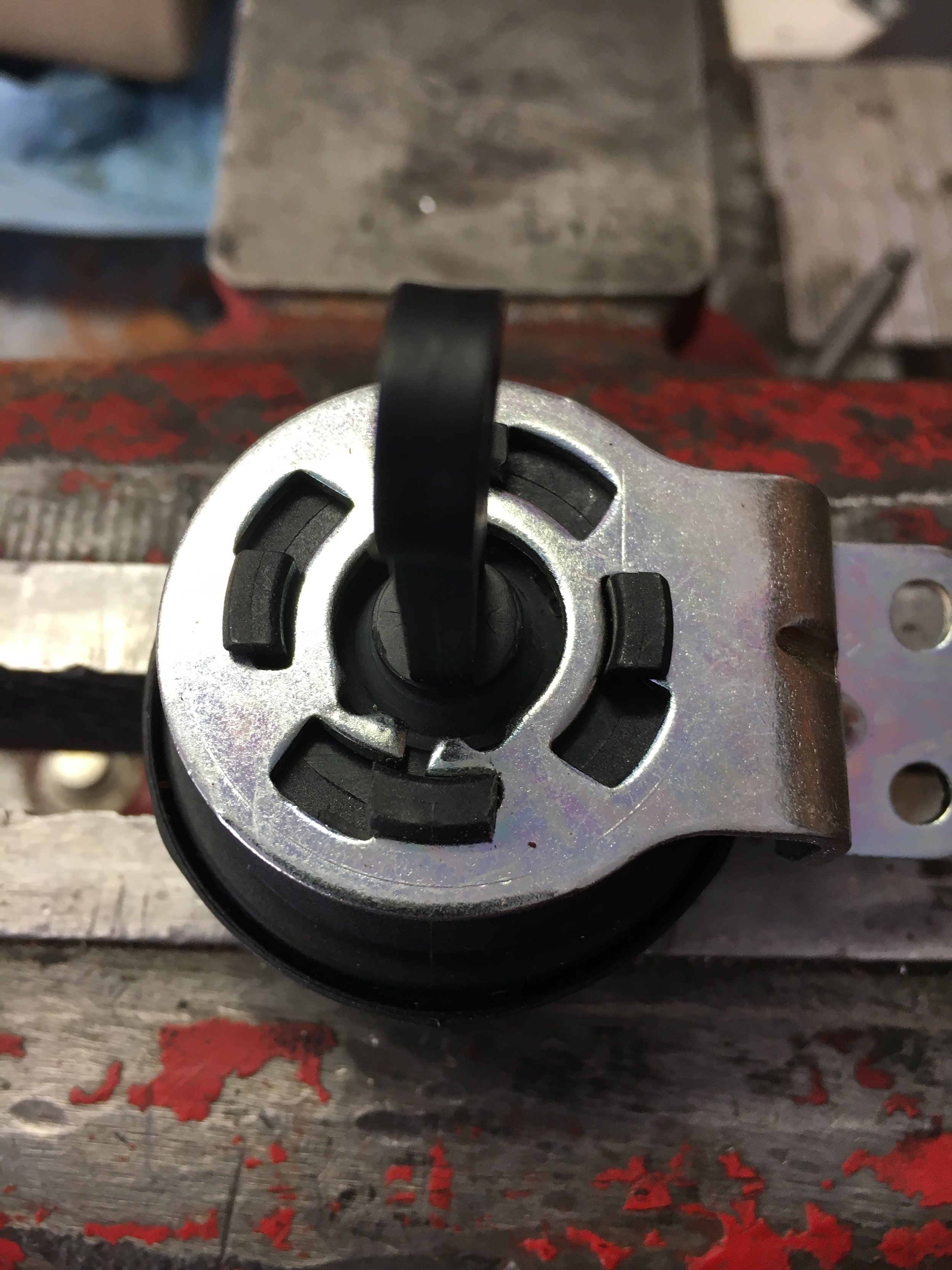
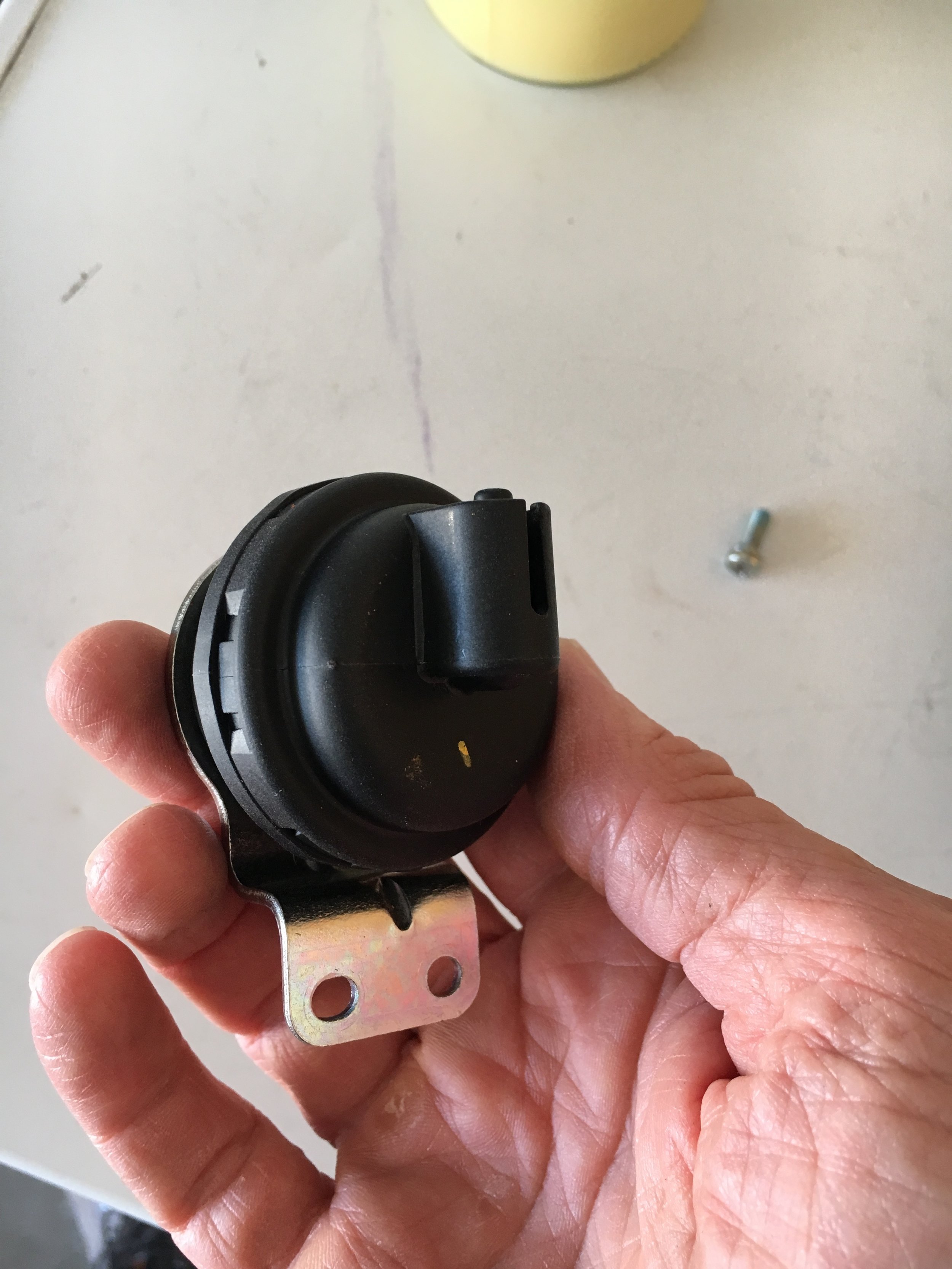
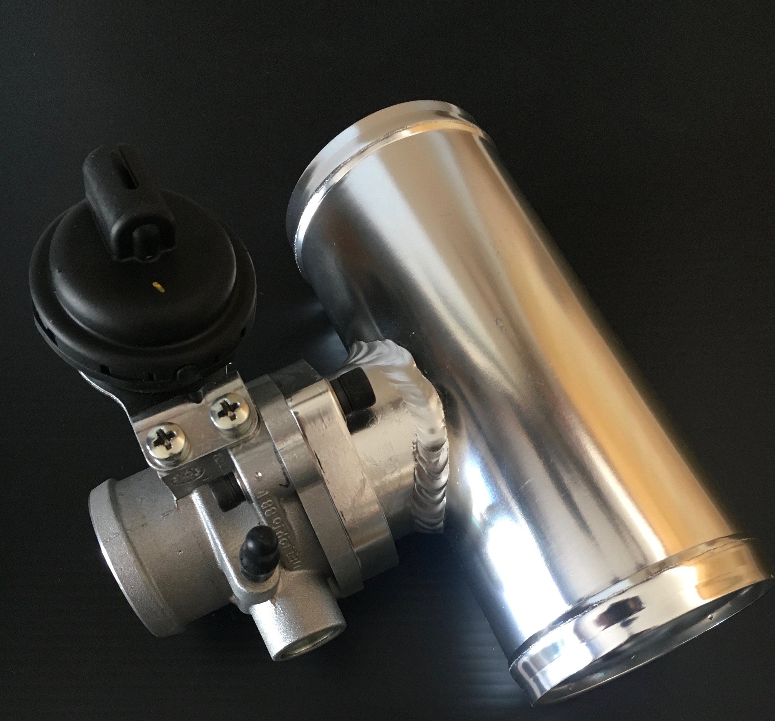
As a preliminary matter, you may wish to replace the OEM heater shut-off tap in order to gain ample clearance for the blower’s intake snorkel. As shown below, we use a standard Spridget hose to connect an NPT elbow threaded into the OEM heater tap’s base plate to the heater core’s inlet, and installed a brass inline ball valve to the outlet (the function is largely unchanged—though you could put the valve in the inlet hose):
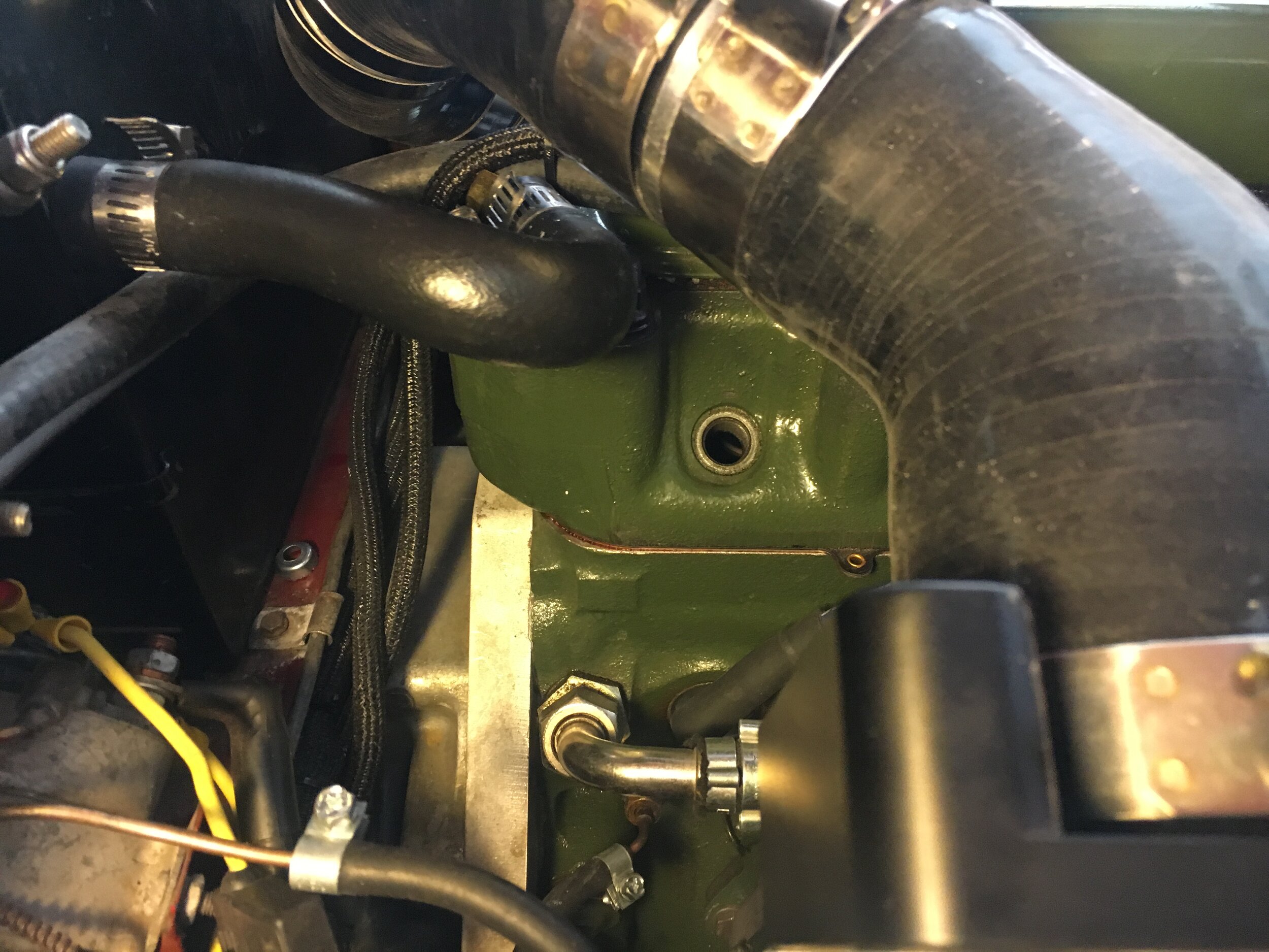
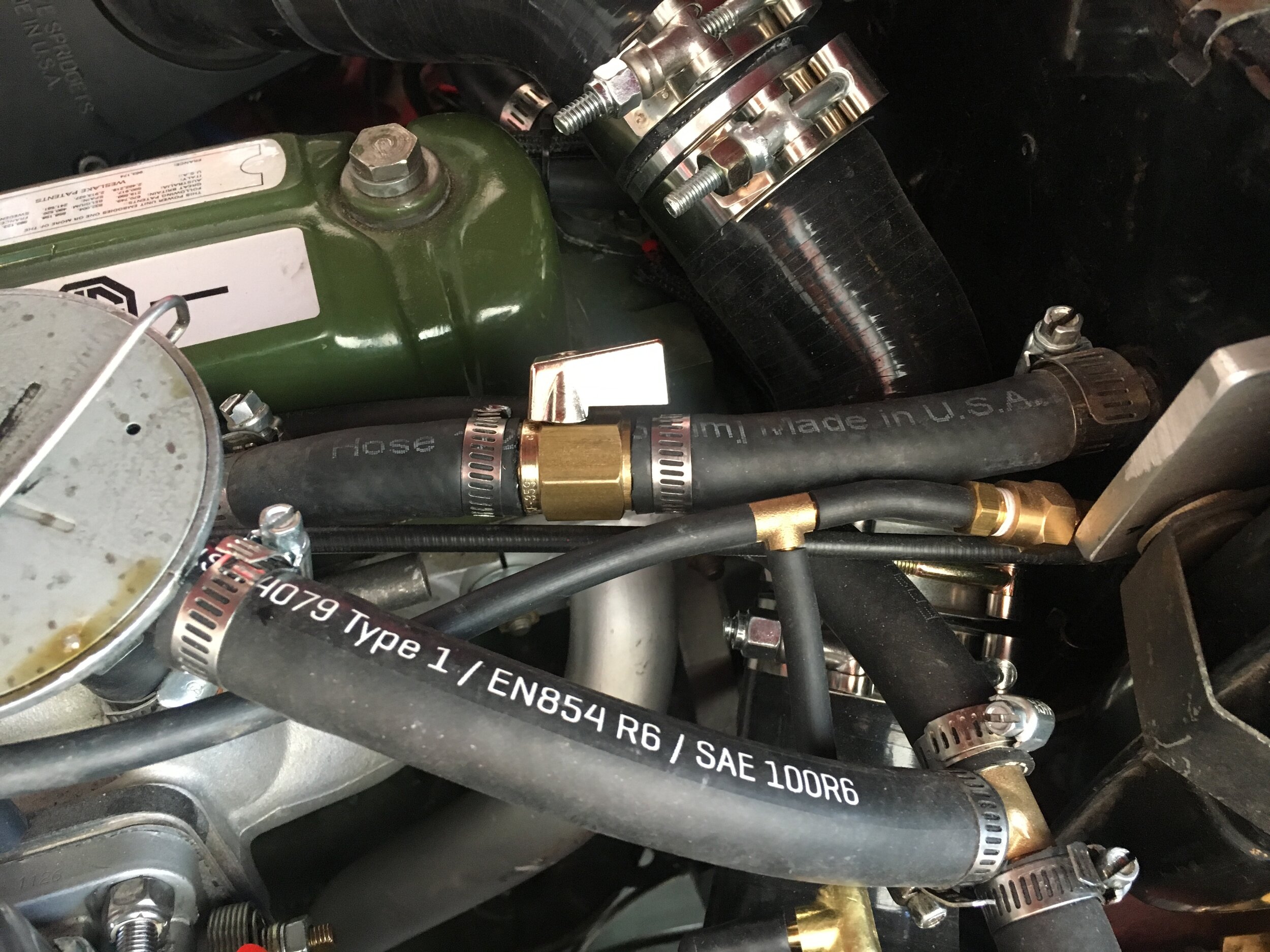
Next, gently pry open the clamshell and replace the OEM spring with the lighter version included with the Creative Spridgets bypass valve adapter:
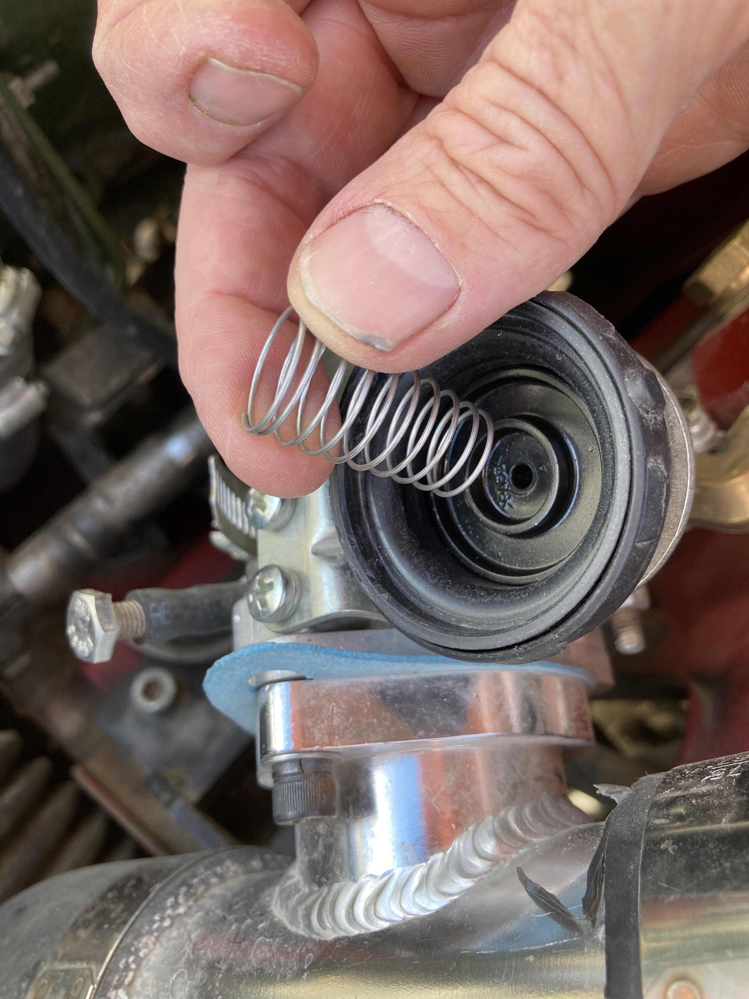
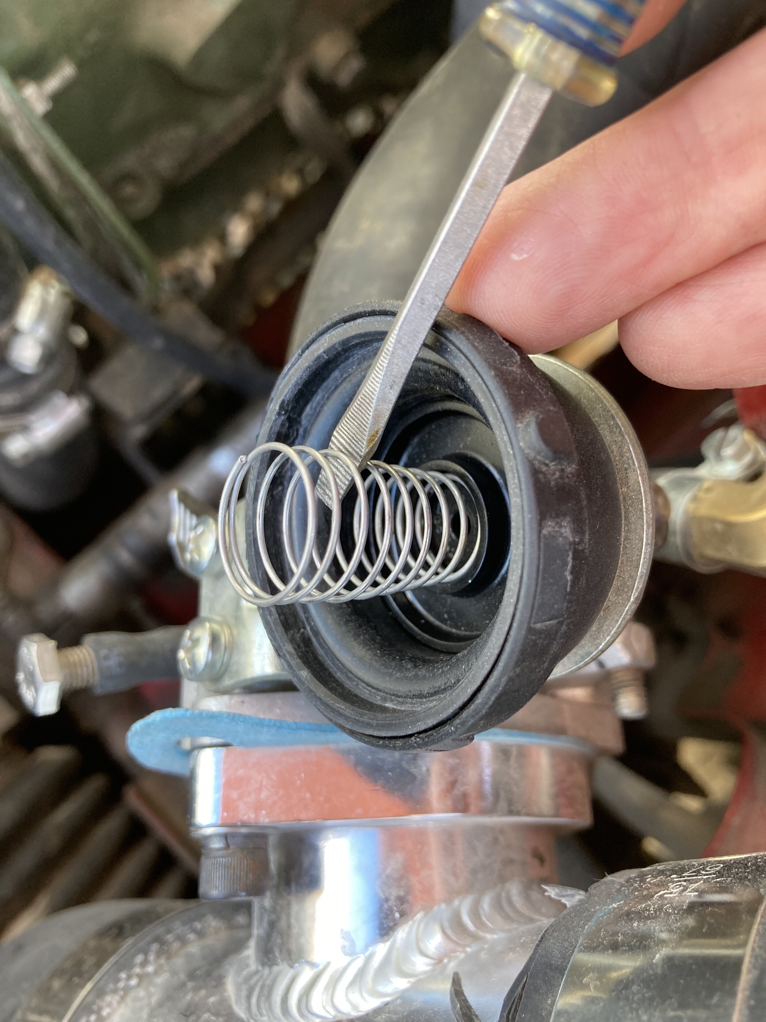
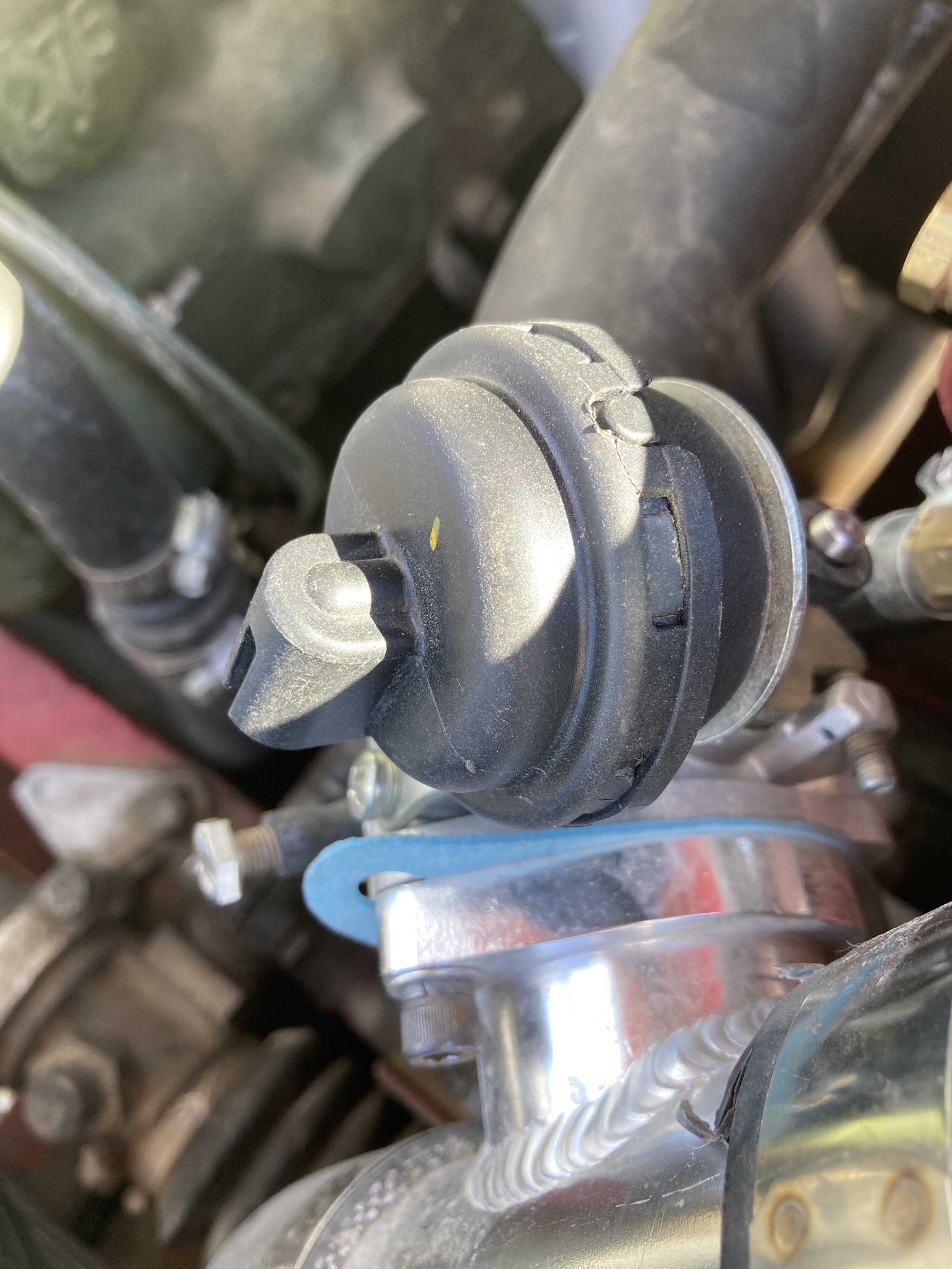
One of the first owners to get his car roadworthy has discovered an effective method of removing the cover without damage, pictured below. He recommends forming a .025” feeler gauge to the curvature os the valve body, then cutting it into 6 pieces with a cutoff wheel before deburring them. Finally, insert the pieces between the body and the cover at each tab, lubricating them with a little WD-40:
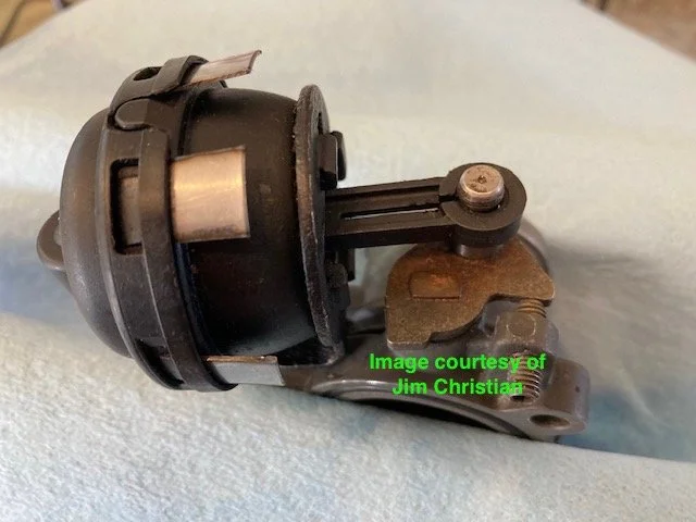
If you crack one or two receptacles on the cover, it will still retain the spring, as shown in the first photo below. Two adjacent areas or too many total—as shown in the second photo—may cause the cover to pop loose during operation, resulting in loss of the spring and difficulty limping home:
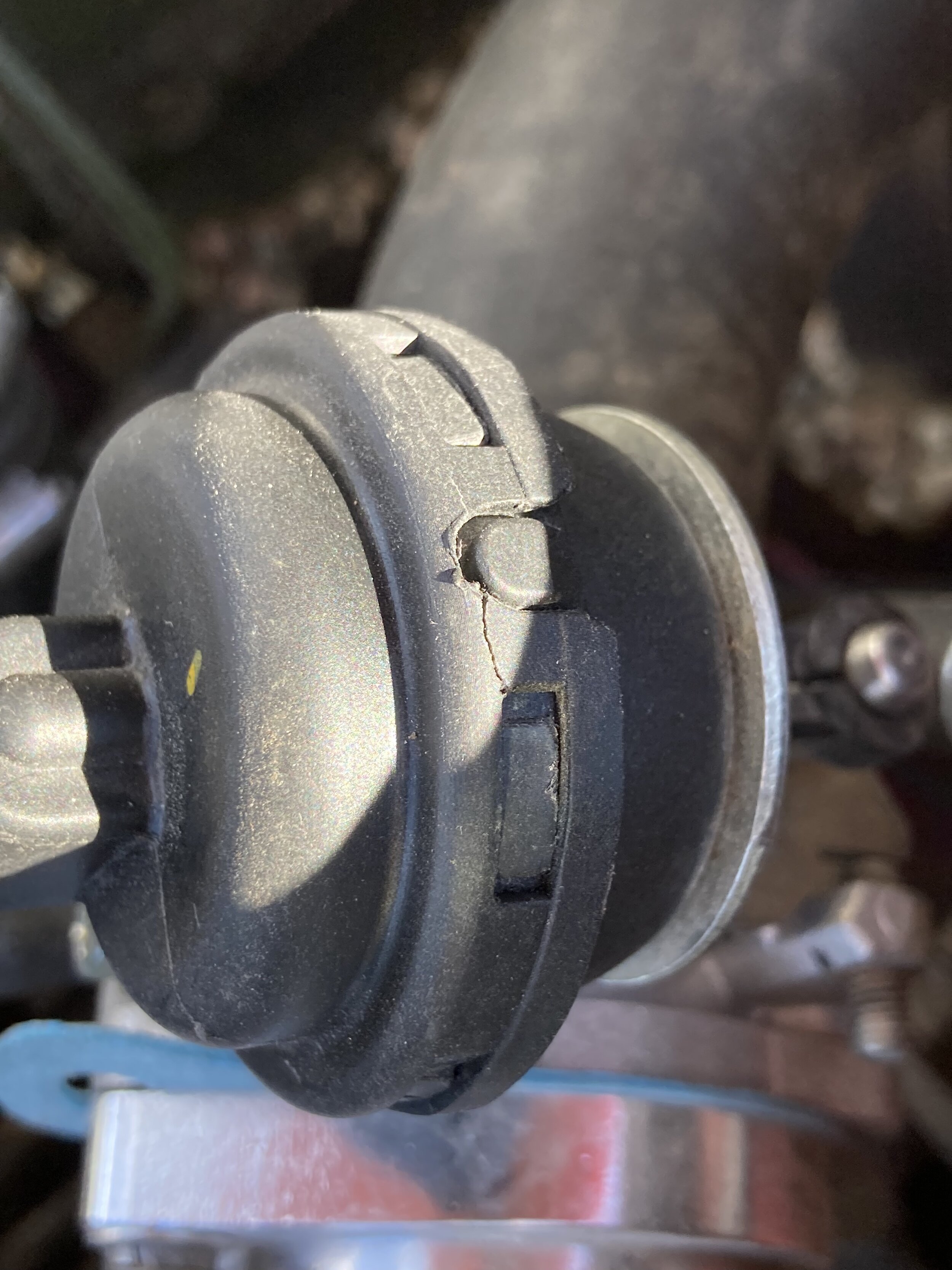
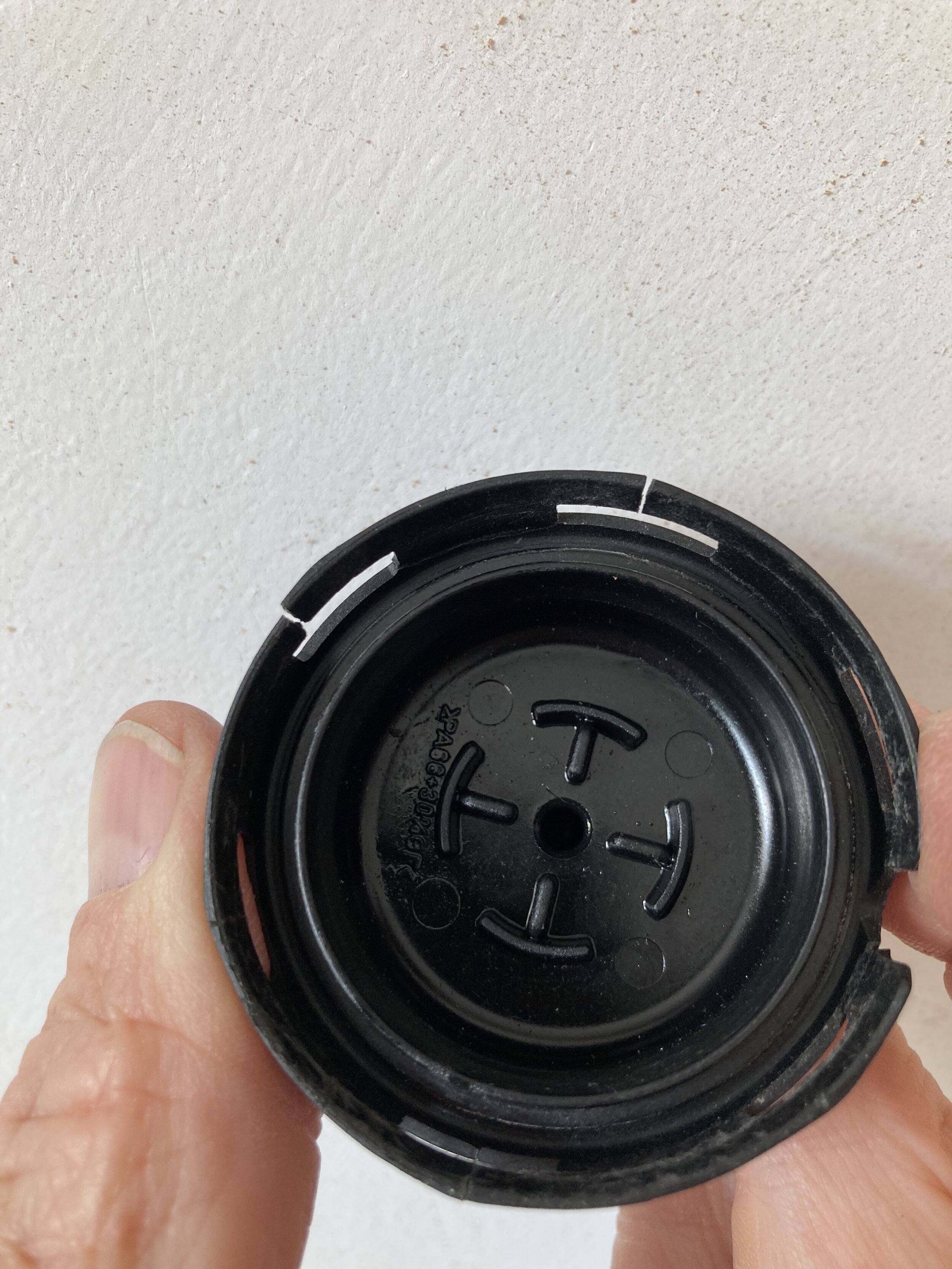
You can, however, use fine mechanic’s wire (such as that used to retain drilled bolts) to secure even a damaged cover. Just make sure the wire does not interfere with the diaphragm’s plunger.
Now, plumb the bypass circuit.
The circuit is composed of the following components, proceeding clockwise from the top in the next image—but keeping in mind that we now prefer to swap the blow-off pipes, such that the bypass valve ends up where the GM/Cadillac thermostat housing is in the below photo:
(i) a Gates 21972 1.5” radiator hose, cut, rotated, and rejoined with a 1.5” x 3” aluminum joiner nipple; (ii) the Mini Cooper S bypass valve; (iii) the Creative Spridgets bypass valve adapter; (iv) a paper gasket treated with high-tack (not silicone or other material that will crumble and get drawn into the engine); (v) the first of two blow-off pipes; (vi) a 3” to 2.5” 90-degree reducing elbow—which attaches to the HIF44 snorkel adapter; (vii) a 45-degree 2.5” elbow; (viii) the second blow-off pipe fitted with the GM/Cadillac pressed steel thermostat housing and a Felpro paper gasket treated with high-tack; and (ix) another 45-degree 2.5” elbow.

The lower portion in the above photo connects the carburetor to the intercooler’s output on the left-hand side of the car, via a 2.5” to 2” reducer; the upper portion allows fresh, unpressurized air to go directly to the carburetor—thus bypassing the supercharger—under steady-state cruising, trailing throttle, and other low-boost conditions.
Here is a photo series showing how the components are prepared and fit together—save for clamps. You may use T-bolt clamps, available for surprisingly little money together with the silicone elbows from Squirrelly on Amazon (with free shipping), or regular hose clamps, as there is very little pressure on the system:
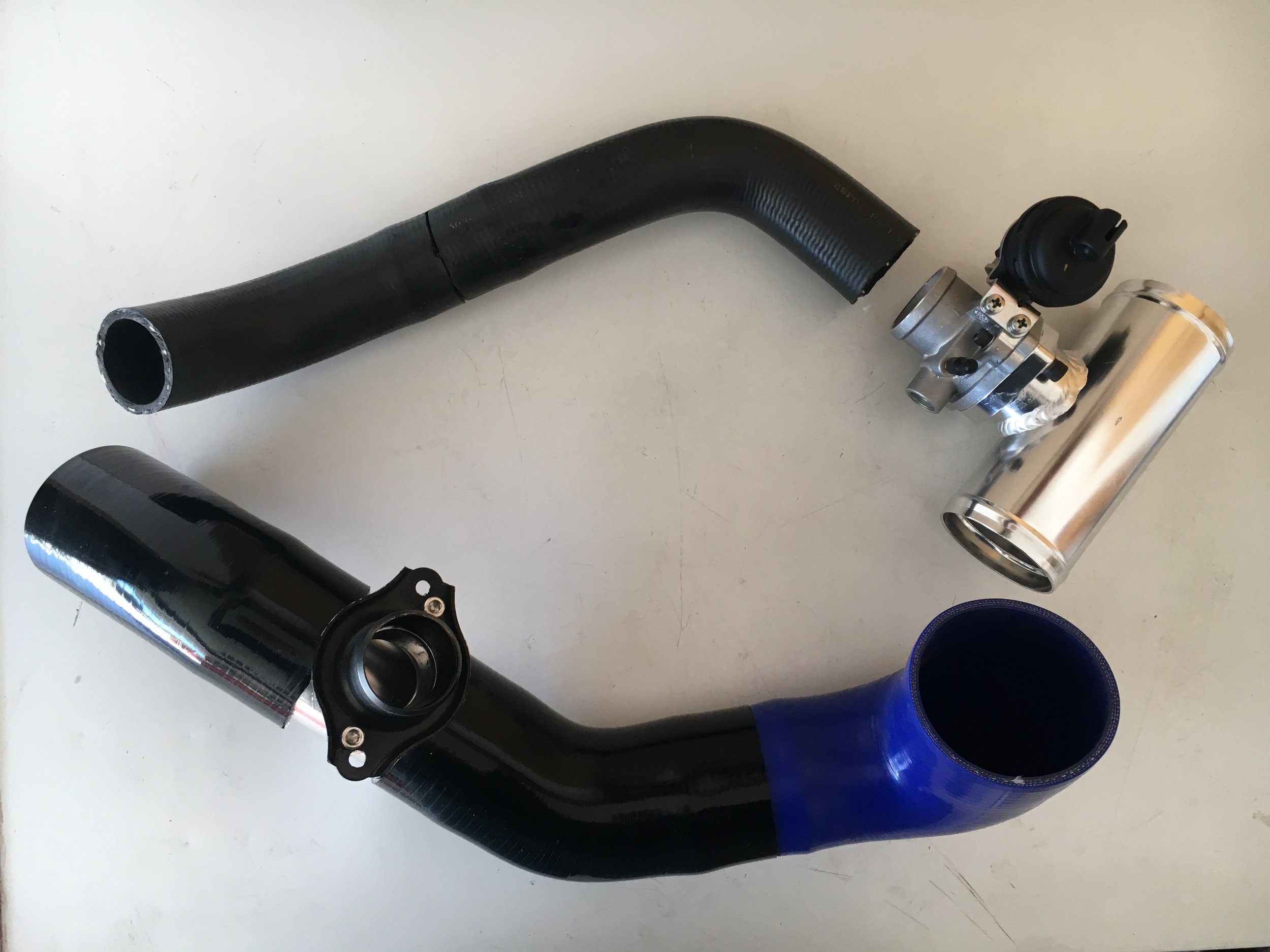
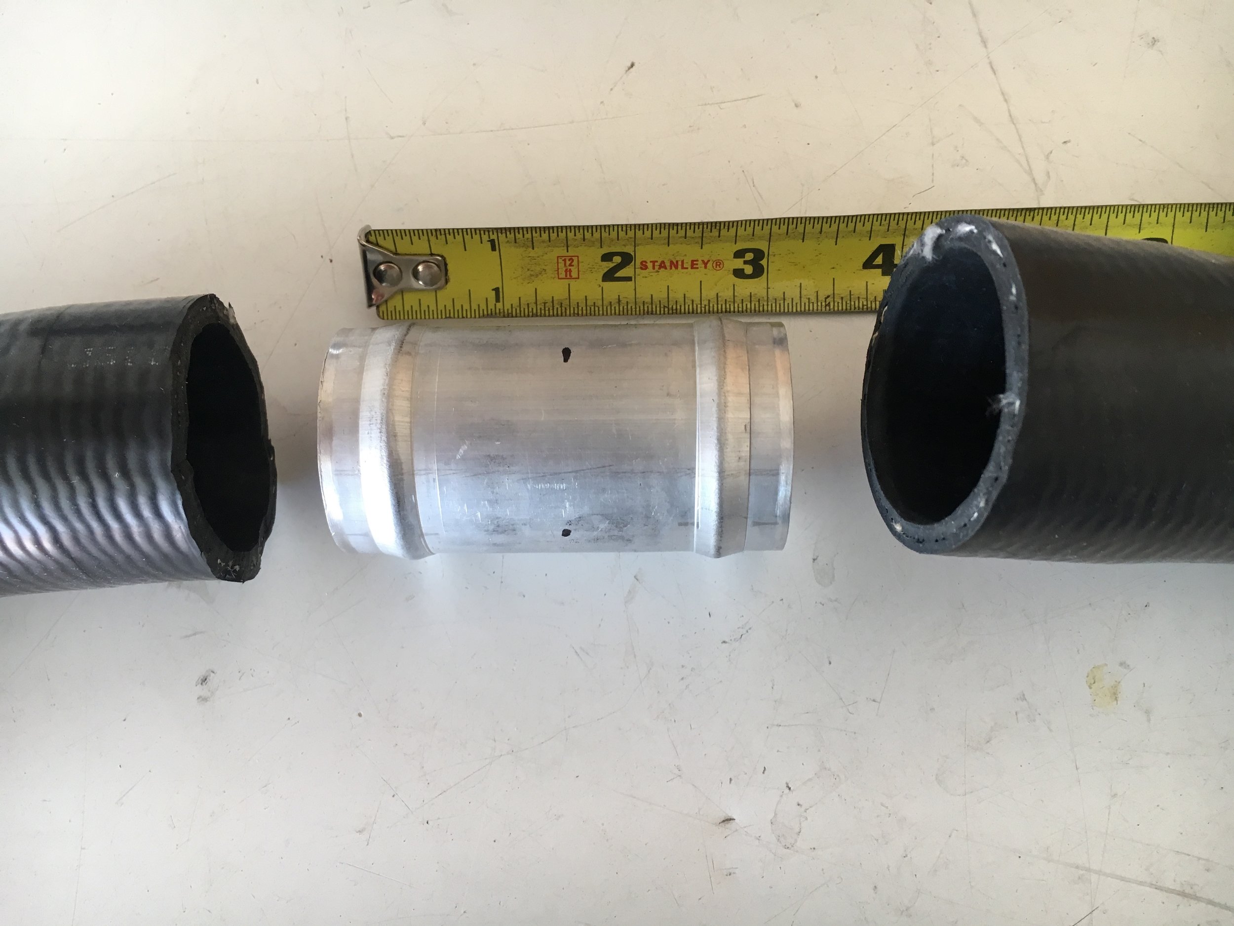
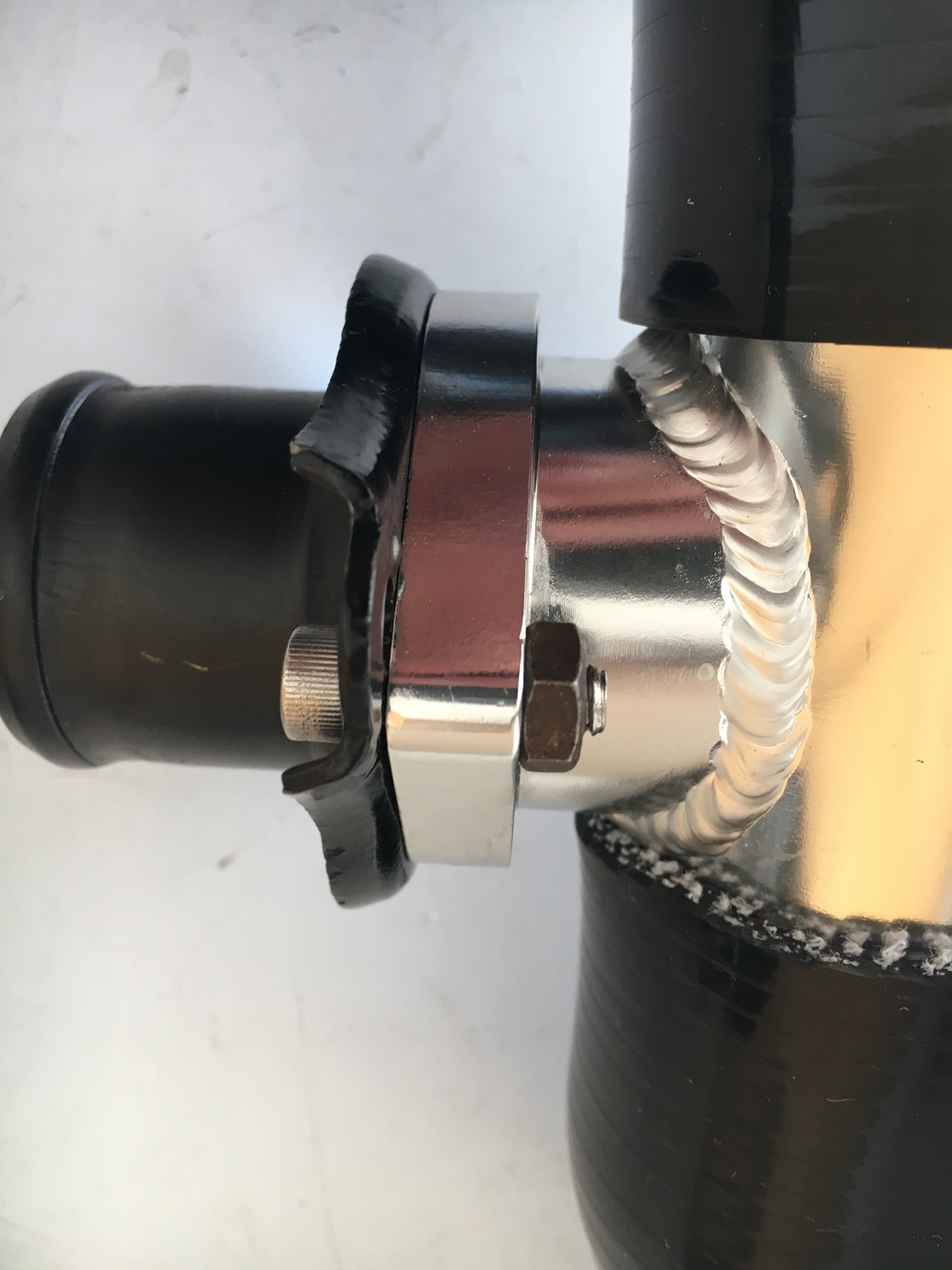
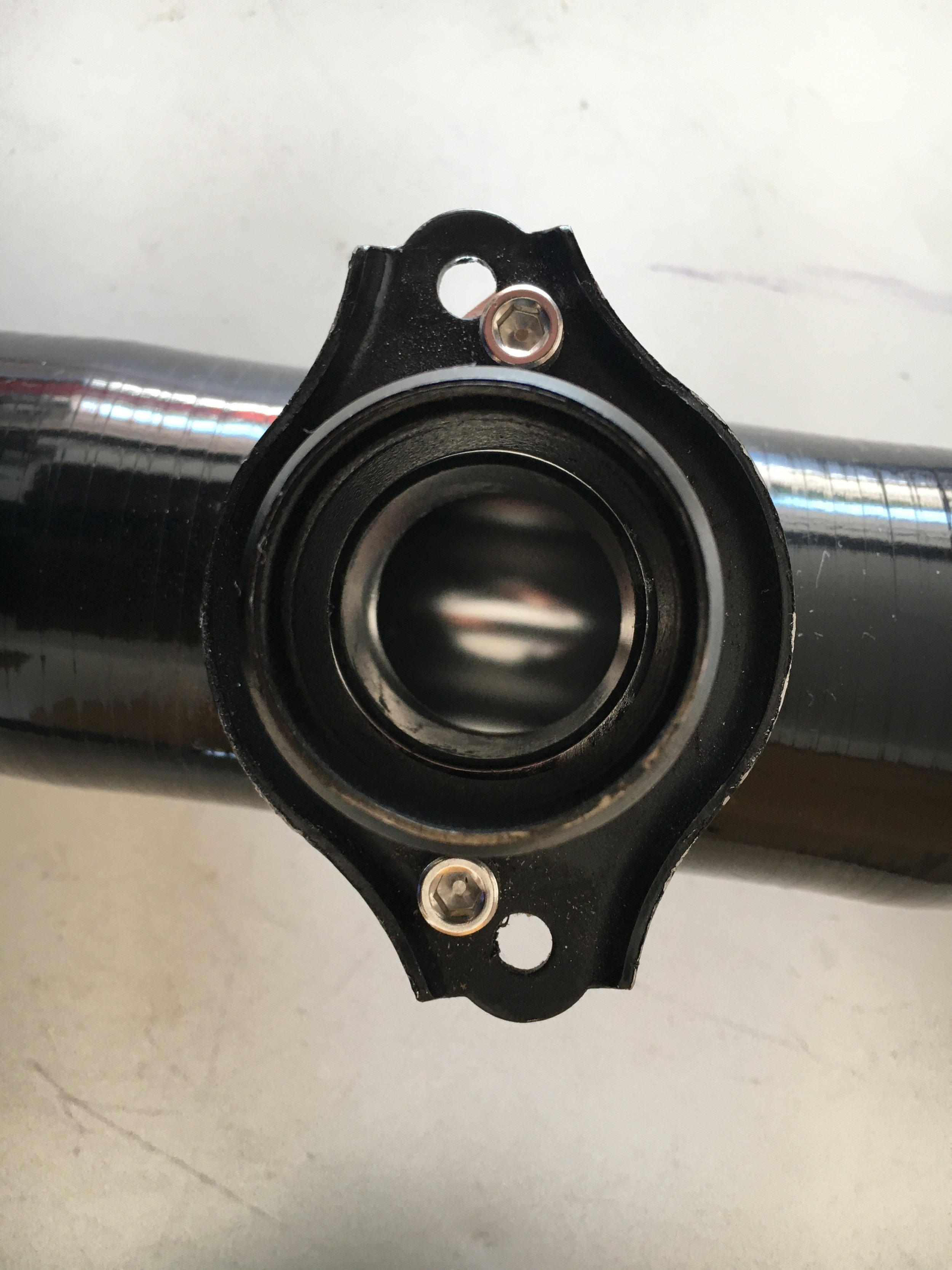
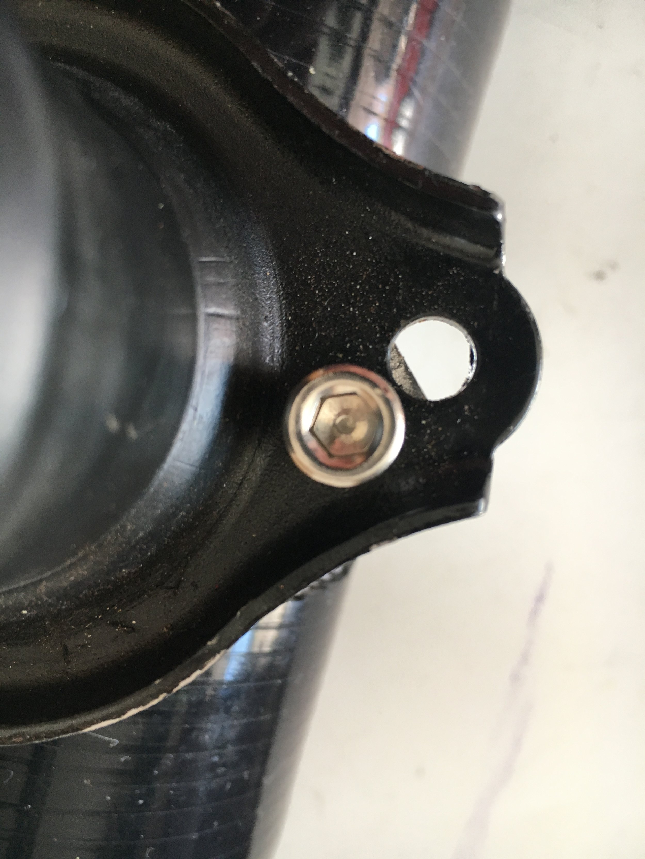
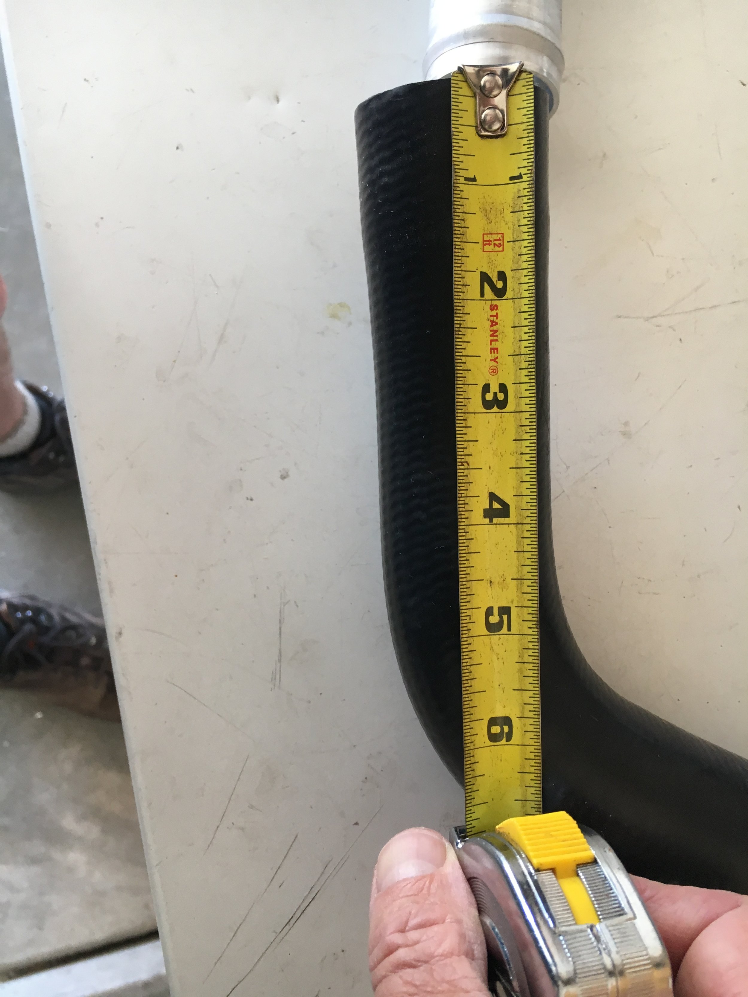
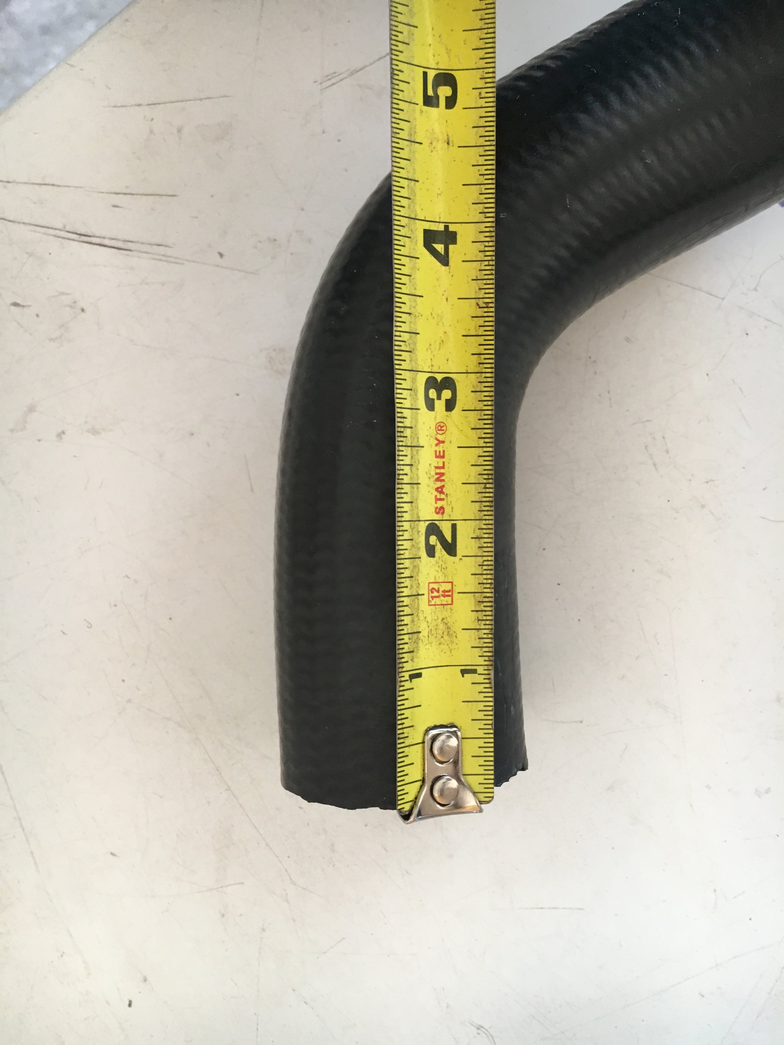
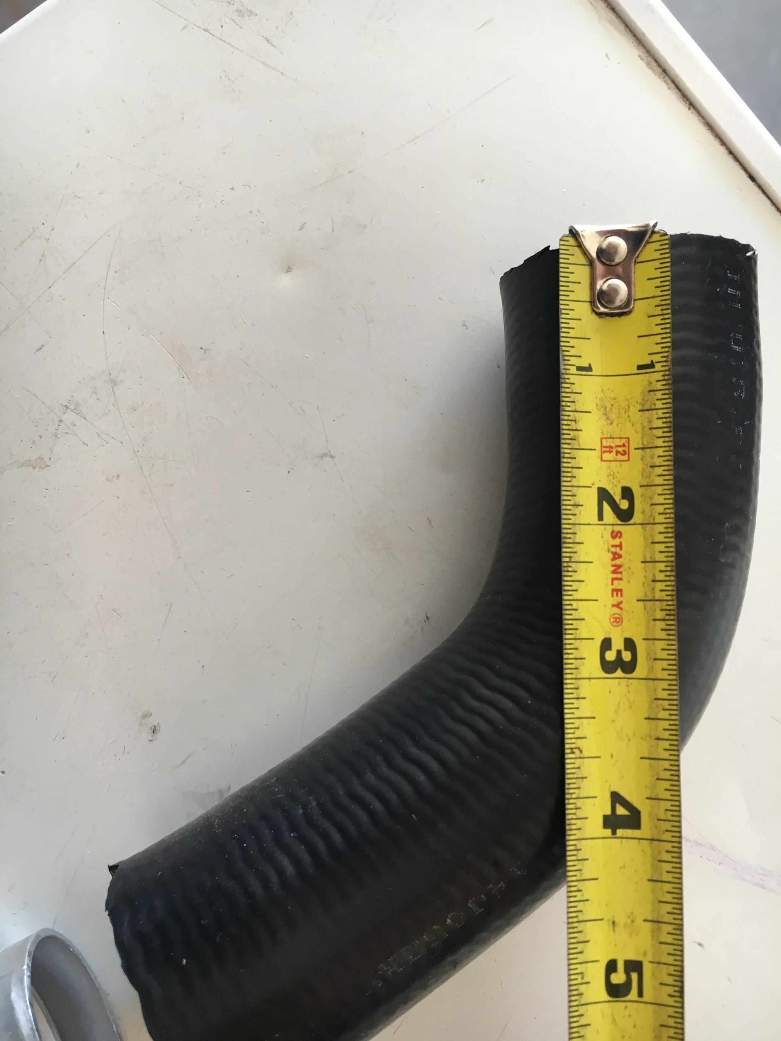
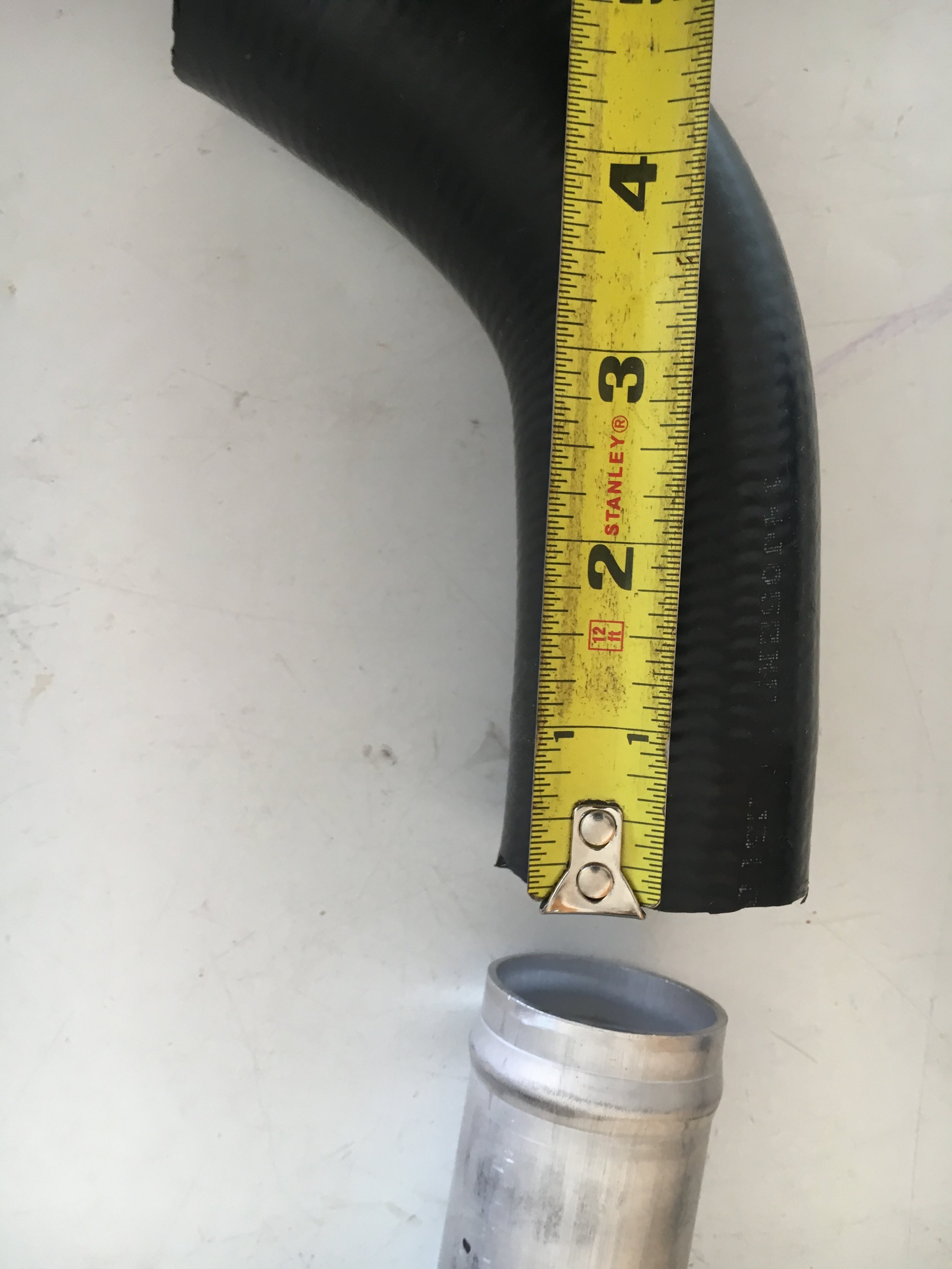
Note two things about the above slideshow:
First, there are no gaskets installed where they would normally reside. During final assembly, you need gaskets (you may treat them with high-tack but do not need to) between the first blow-off pipe and the Creative Spridgets bypass valve adapter and between the second blow-off pipe and the GM/Cadillac thermostat housing.
Second, you must either redrill the GM/Cadillac thermostat housing to match the blow-off pipe’s bolt pattern or elongate the housing’s holes—depending on whether you use two type ‘S’ blow-off valve pipes, or one ‘S’ type and one ‘R’ type.
If you ordered two ‘S’ type blow-off pipes, rotate the housing slightly in either direction (as shown in the above slideshow), so as to leave sufficient metal between the bolt holes, ensure that the central bore is aligned. Then use a snugly-fitting drill bit inserted through the holes in the blow-off pipe’s flange to mark where you will drill the thermostat housing. When drilling steel, as always, use plenty of oil and take your time.
If you ordered one ‘S’ type blow-off pipe to mate with the Creative Spridgets bypass valve adapter, and one ‘R’ type blow-off pipe to mate with the GM/Cadillac thermostat housing, simply elongate the holes in the housing (and the gasket) like this:

It is now time to install the bypass circuit and complete the intake snorkel. Begin by assembling the air cleaner, straight reducer, blow-off pipe with bypass valve attached via the Creative Spridgets adapter or the GM/Cadillac thermostat housing as we prefer, and the 45-degree reducing elbow. You may wish to keep the clamps on the blow-off pipe loose to adjust the angle of the air cleaner and reducing elbow:

Note: the above photo shows a Tee fitting in the vacuum hose feeding the bypass valve’s diaphragm—but there is no such Tee fitting needed (this is an early photo).
Regardless of whether you position the bypass valve at the rear or front end of the circuit, its vacuum line extends directly from the valve’s diaphragm to the metered distributor nipple on the carburetor, as shown here:

Now, insert the assembly under the left-hand fender, where it will draw cool air from ahead of the front wheel. The air cleaner will rest on the wheel housing for the moment:
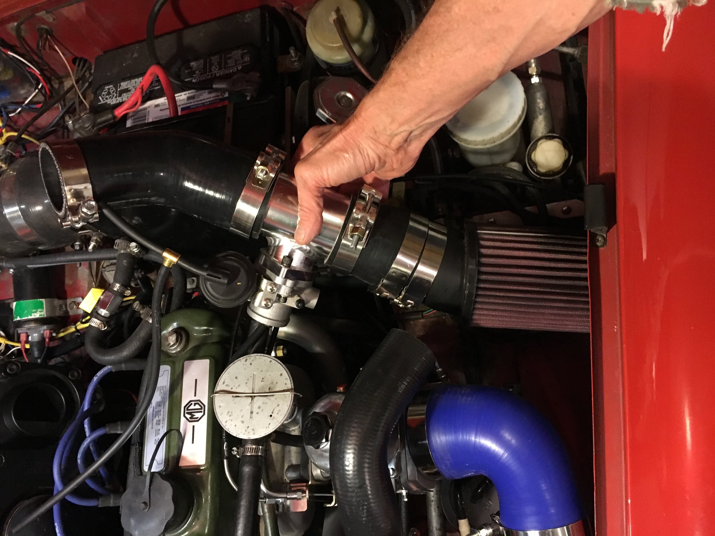
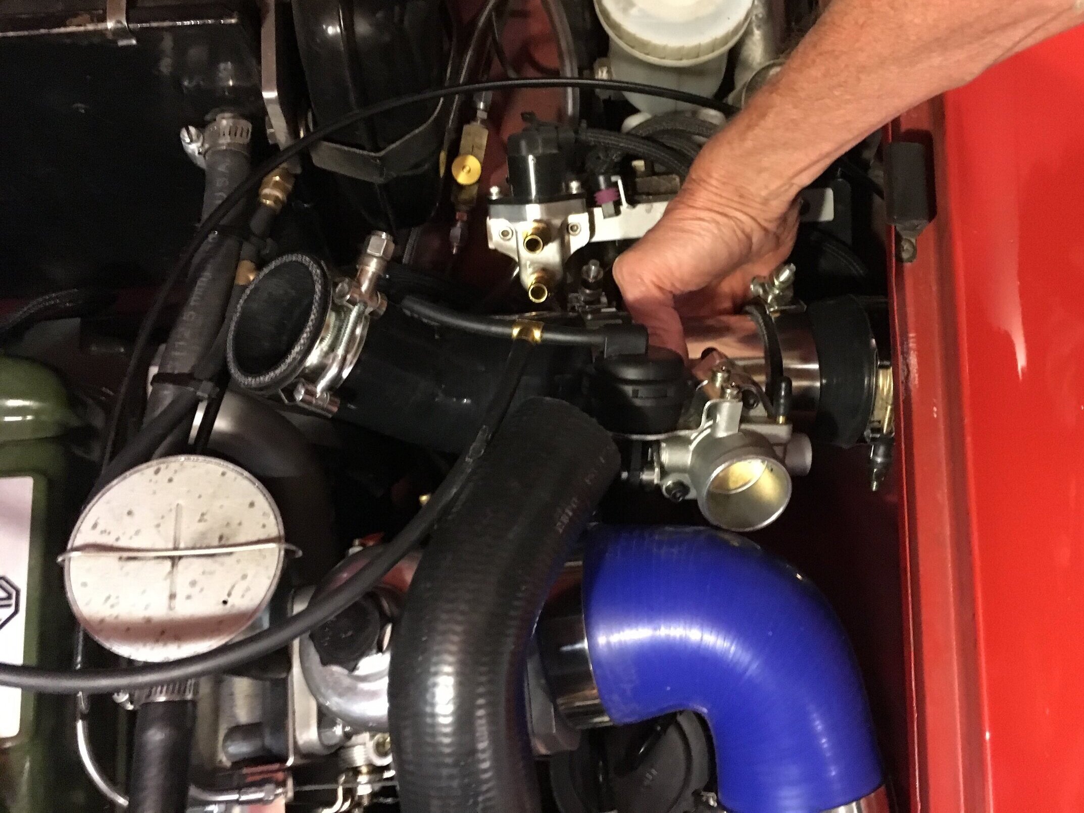
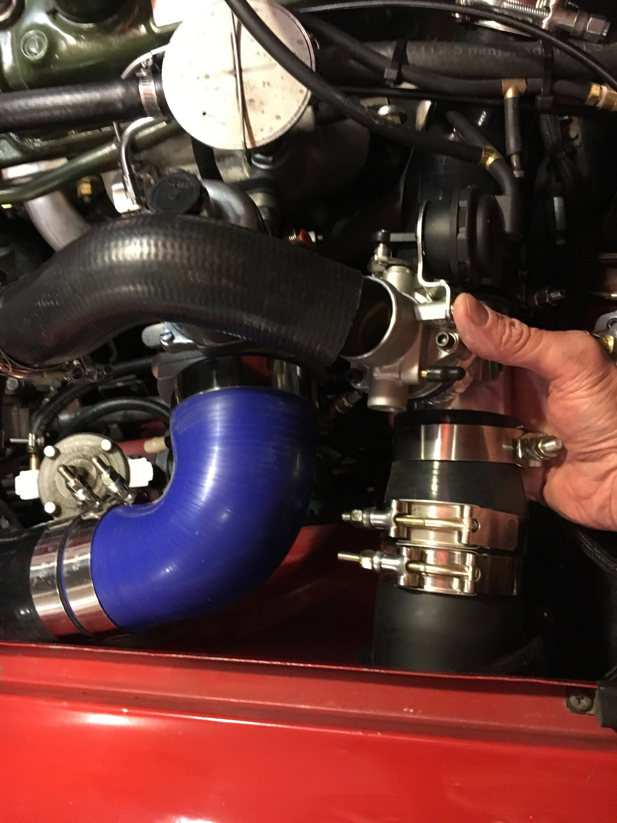
Next, install a 45-degree reducing elbow on the supercharger’s intake, leaving the clamp loose so you can pivot the hose during the next few steps. Note that the OEM heater tap has been replaced by an NPT elbow and inline valve to make room for the snorkel:
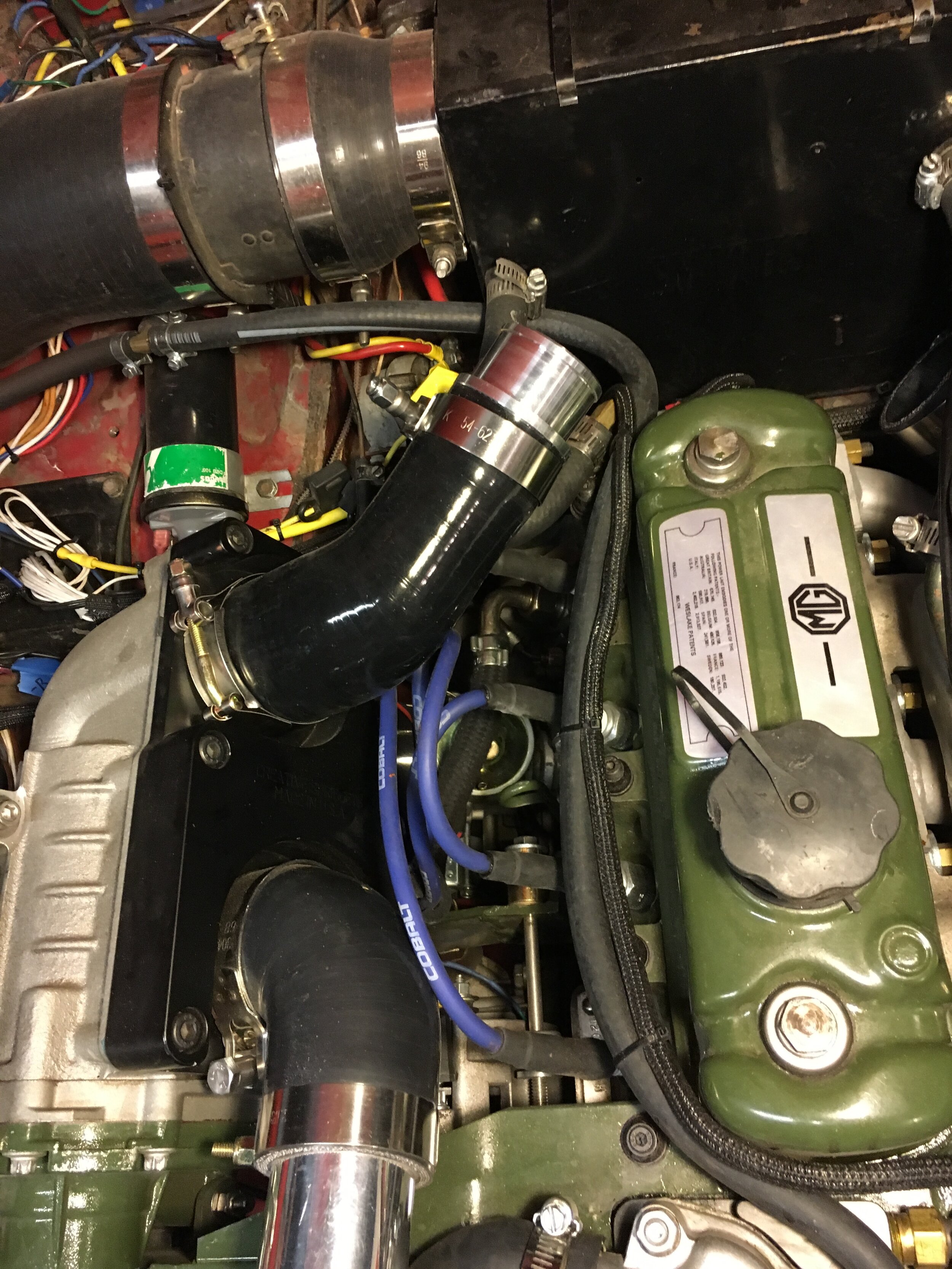
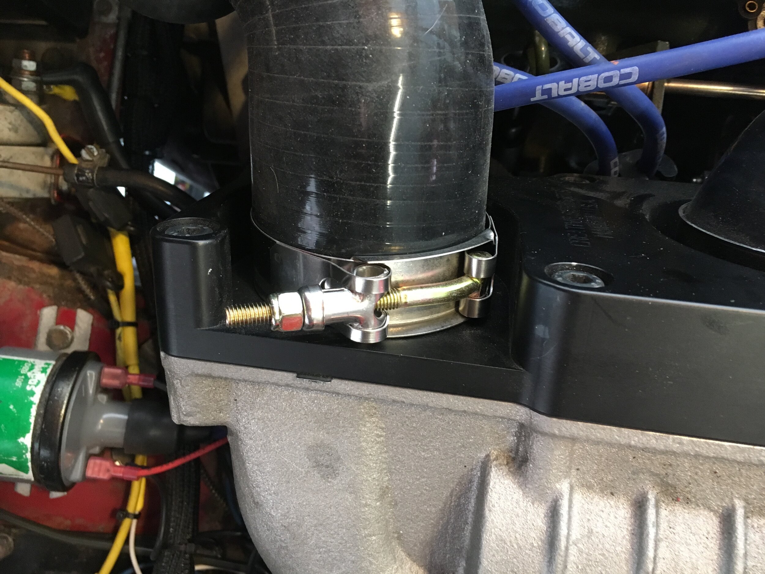
You will now use two 45-degree 2” elbows to bridge the gap between the intake tract and the blower’s inlet. As shown in this series, you will have to shorten one or both of the elbows. We took 1” from one leg of one elbow, and 1-1/4” from one leg of the second, and still ended up with slight contact against the heater box:
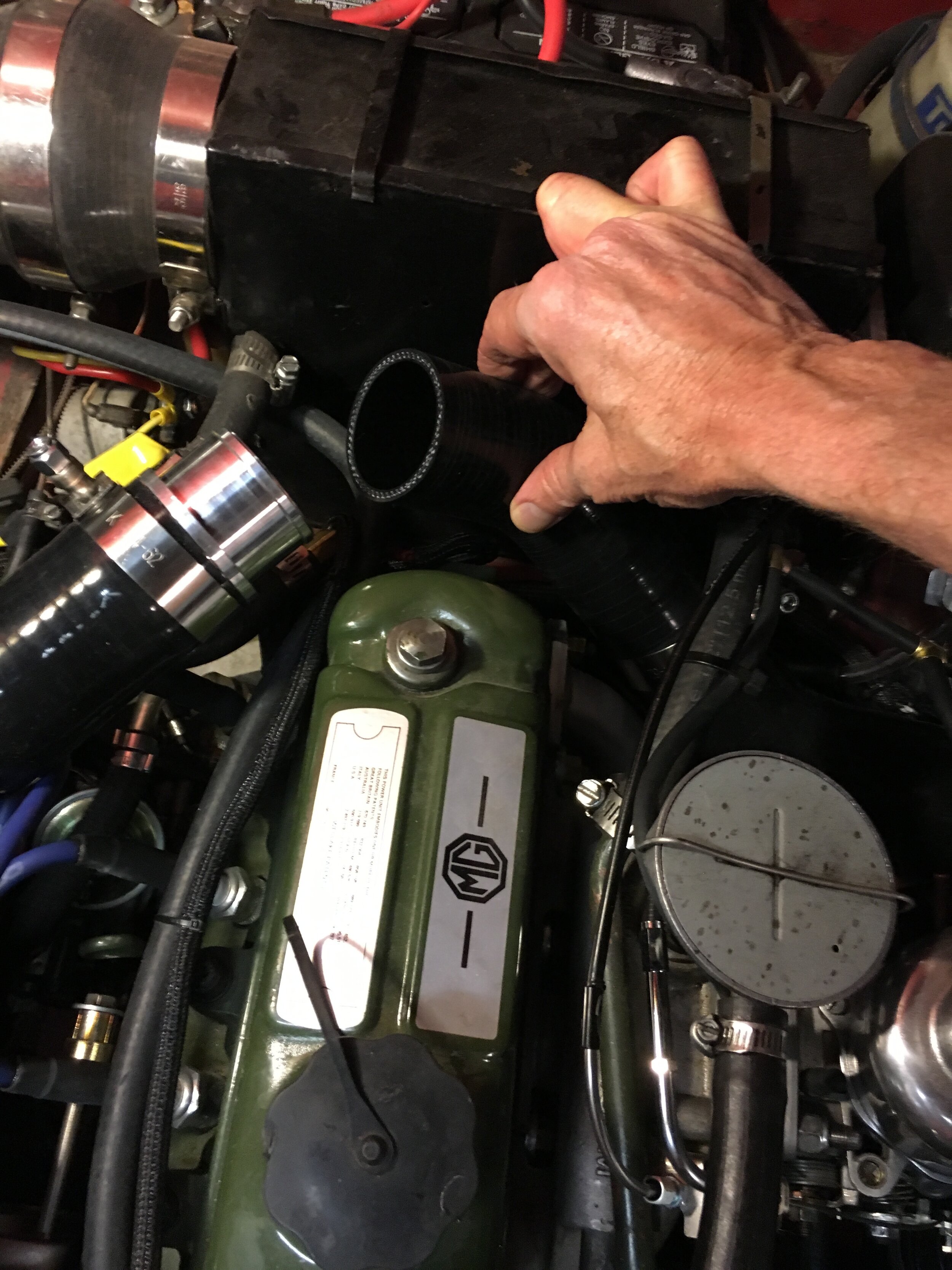
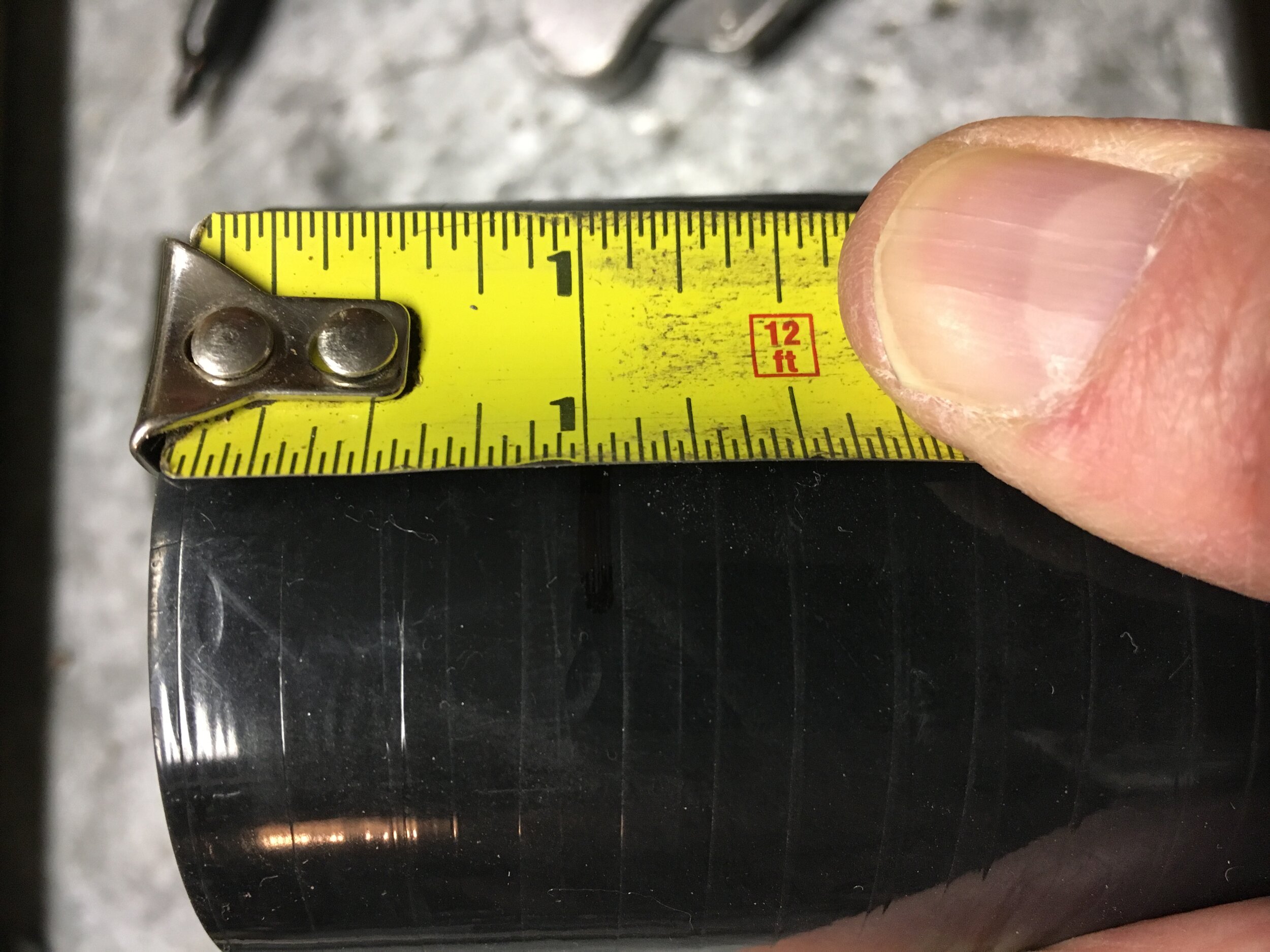
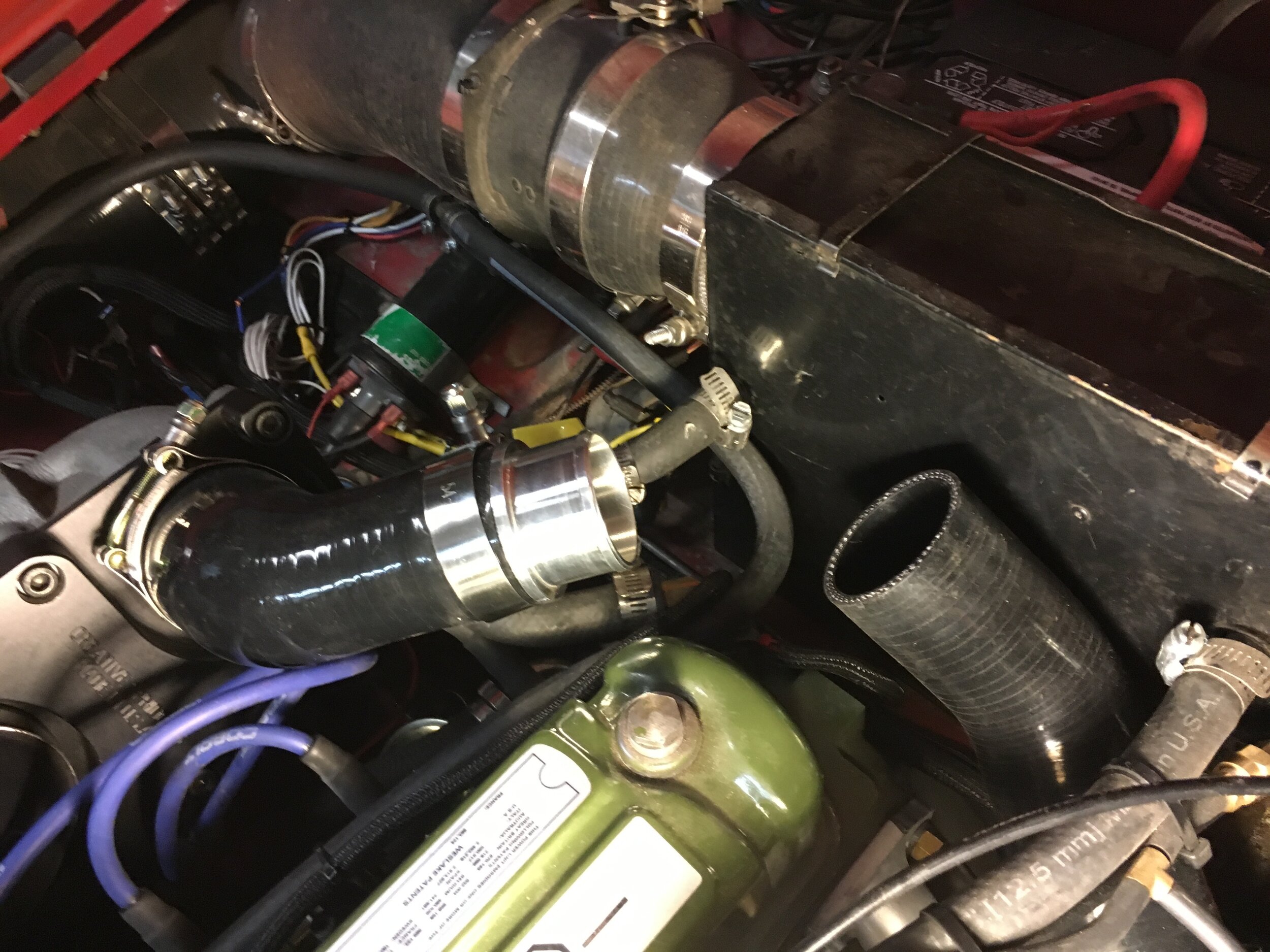
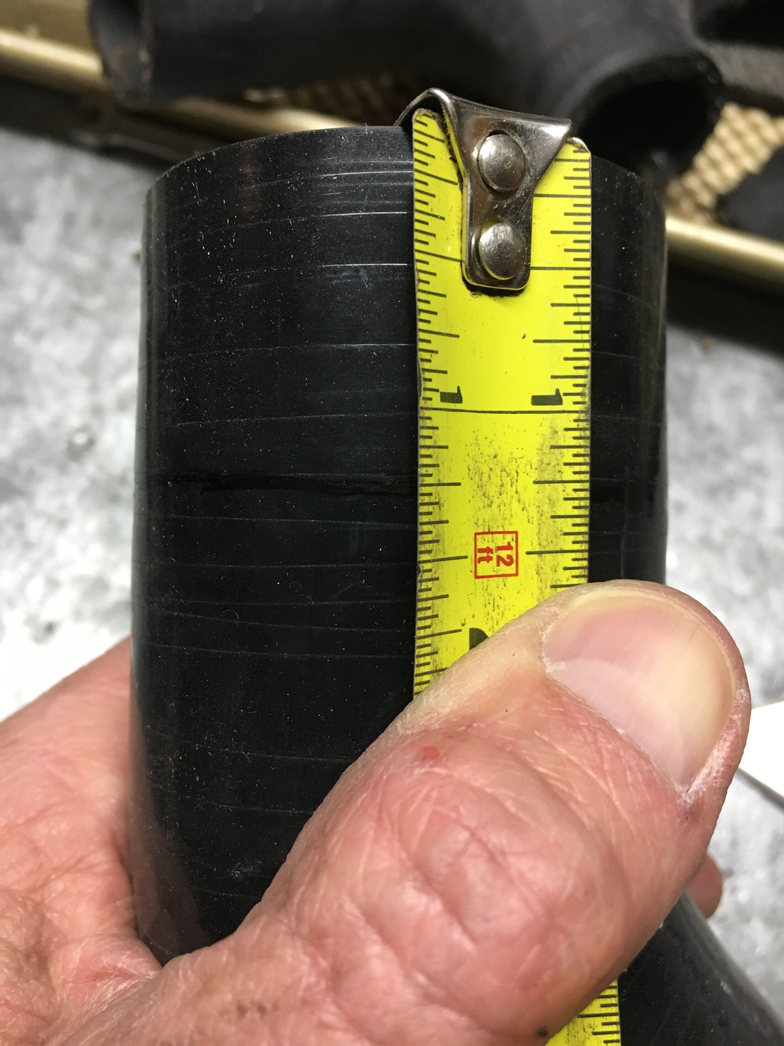
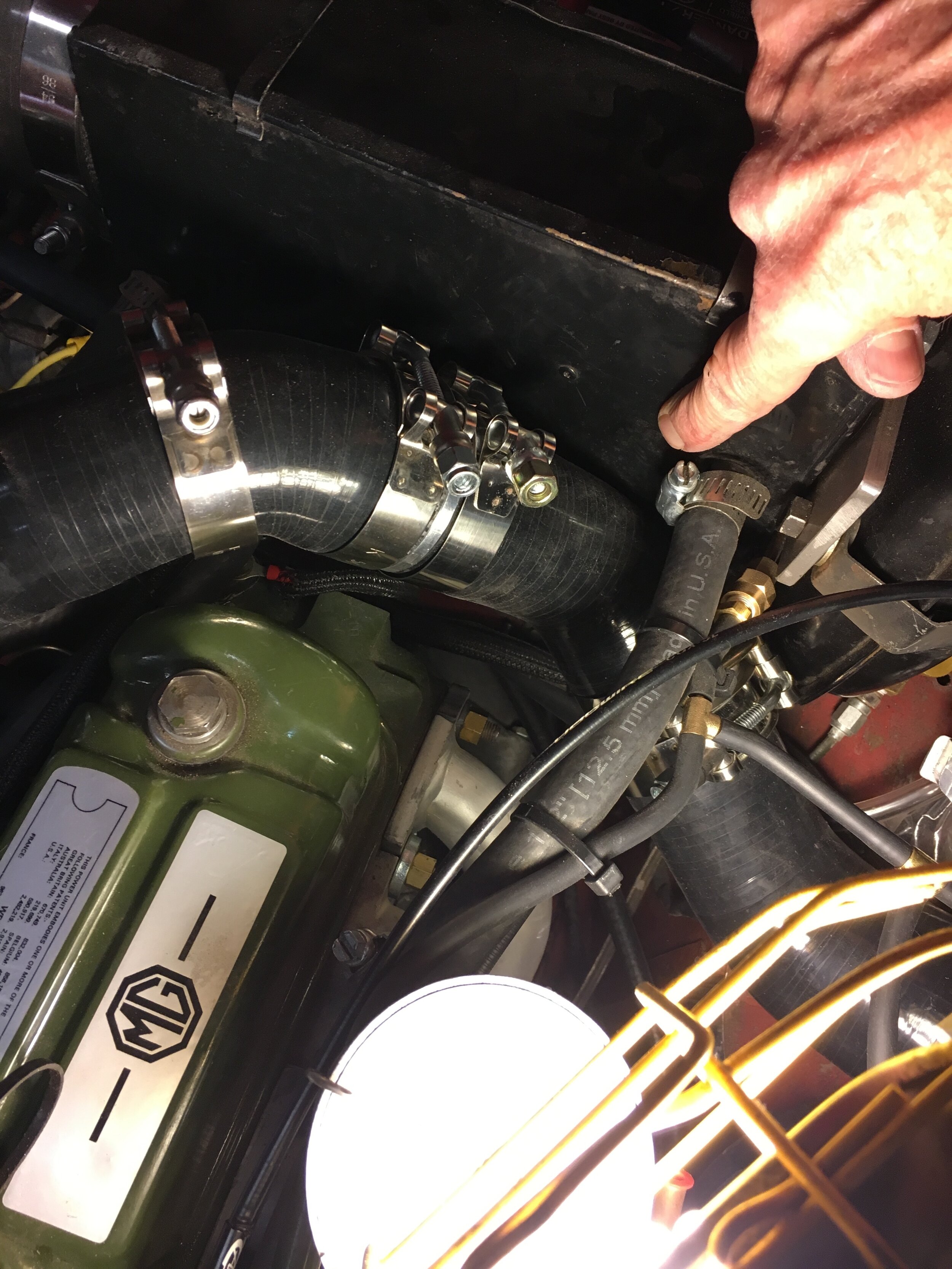
The solution—in our case—was to shorten the small end of the 45-degree reducing elbow attached to the blower’s inlet slightly, which yielded sufficient clearance.
*Note: you should determine your own measurements as you install each respective elbow by trial-and-error:
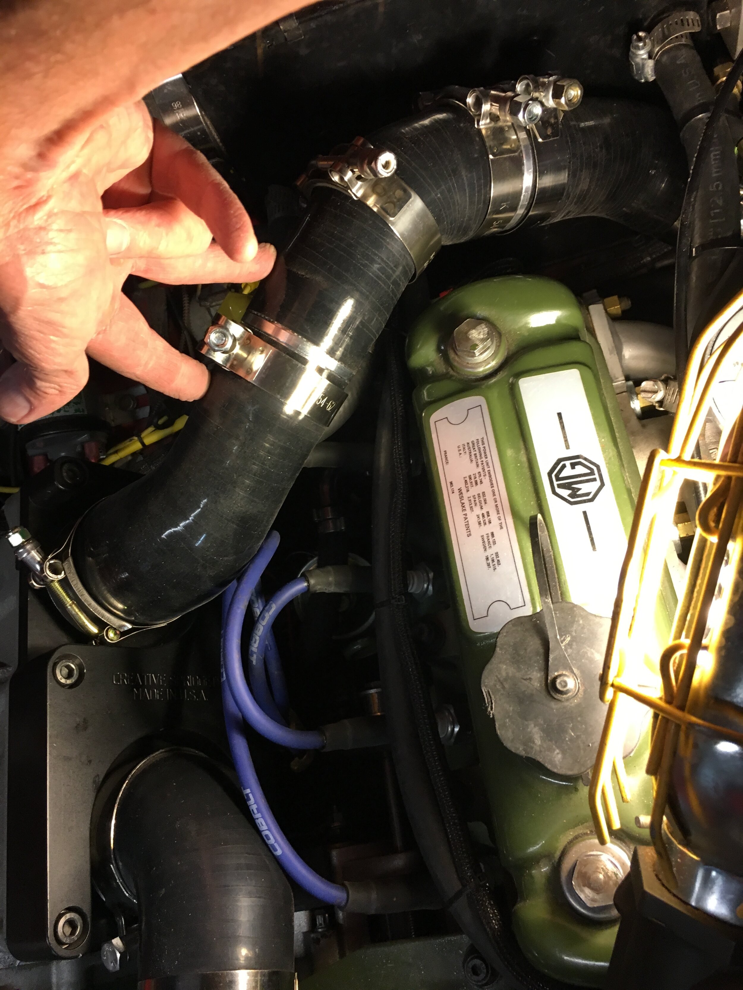
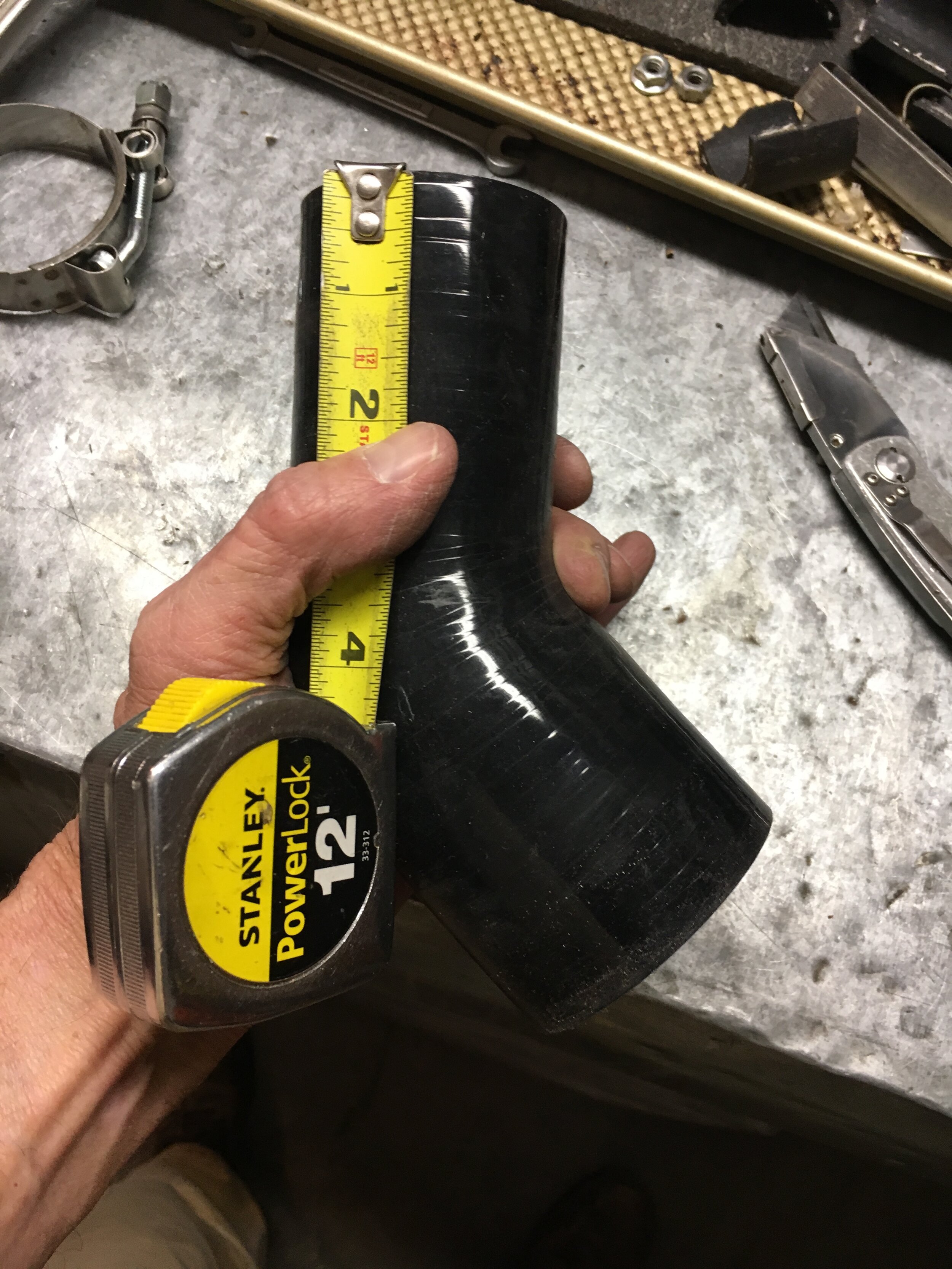
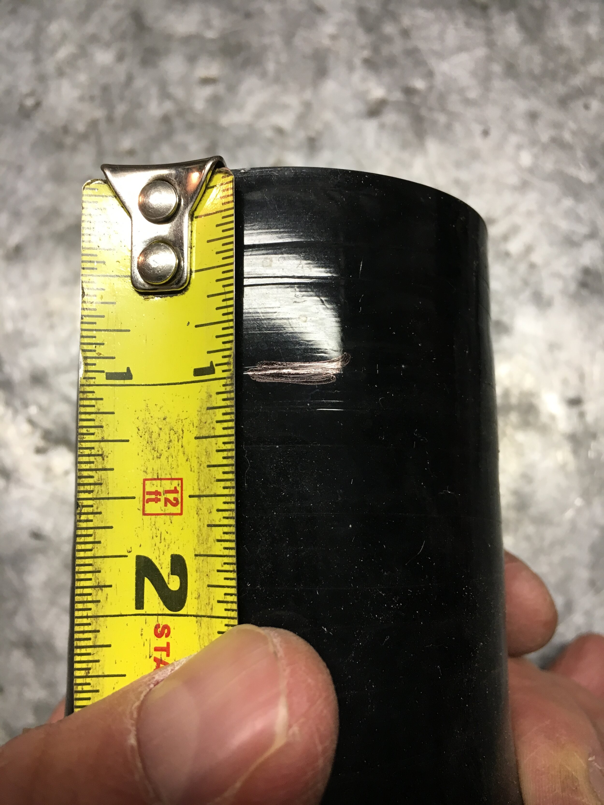
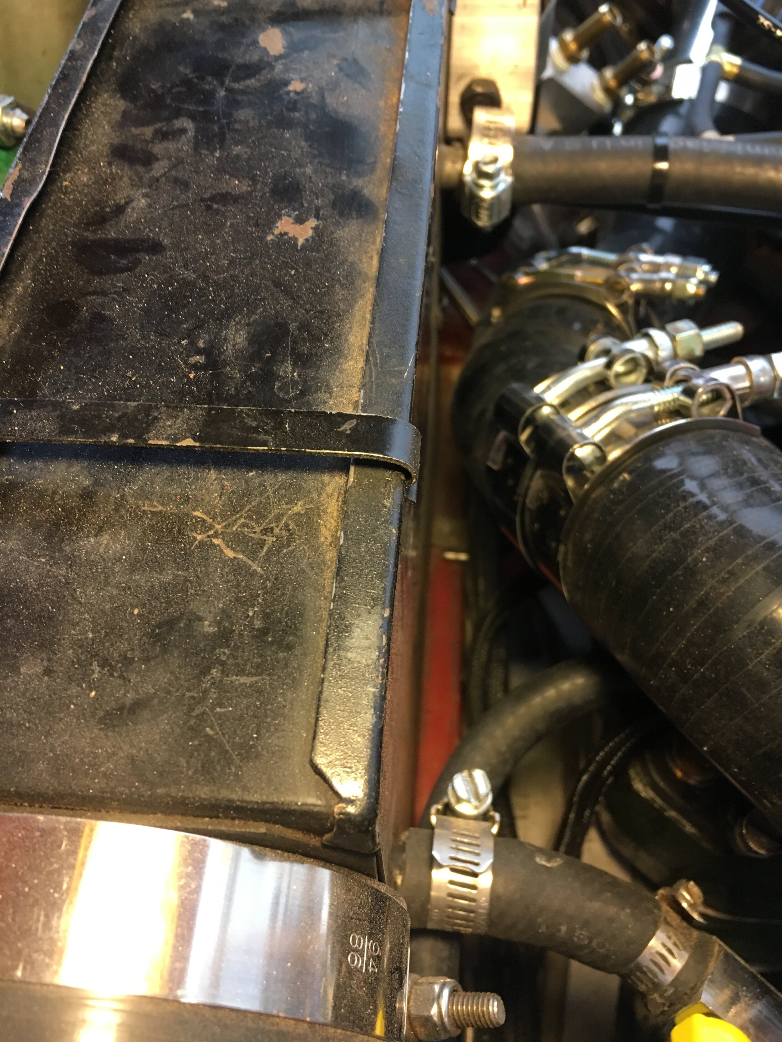
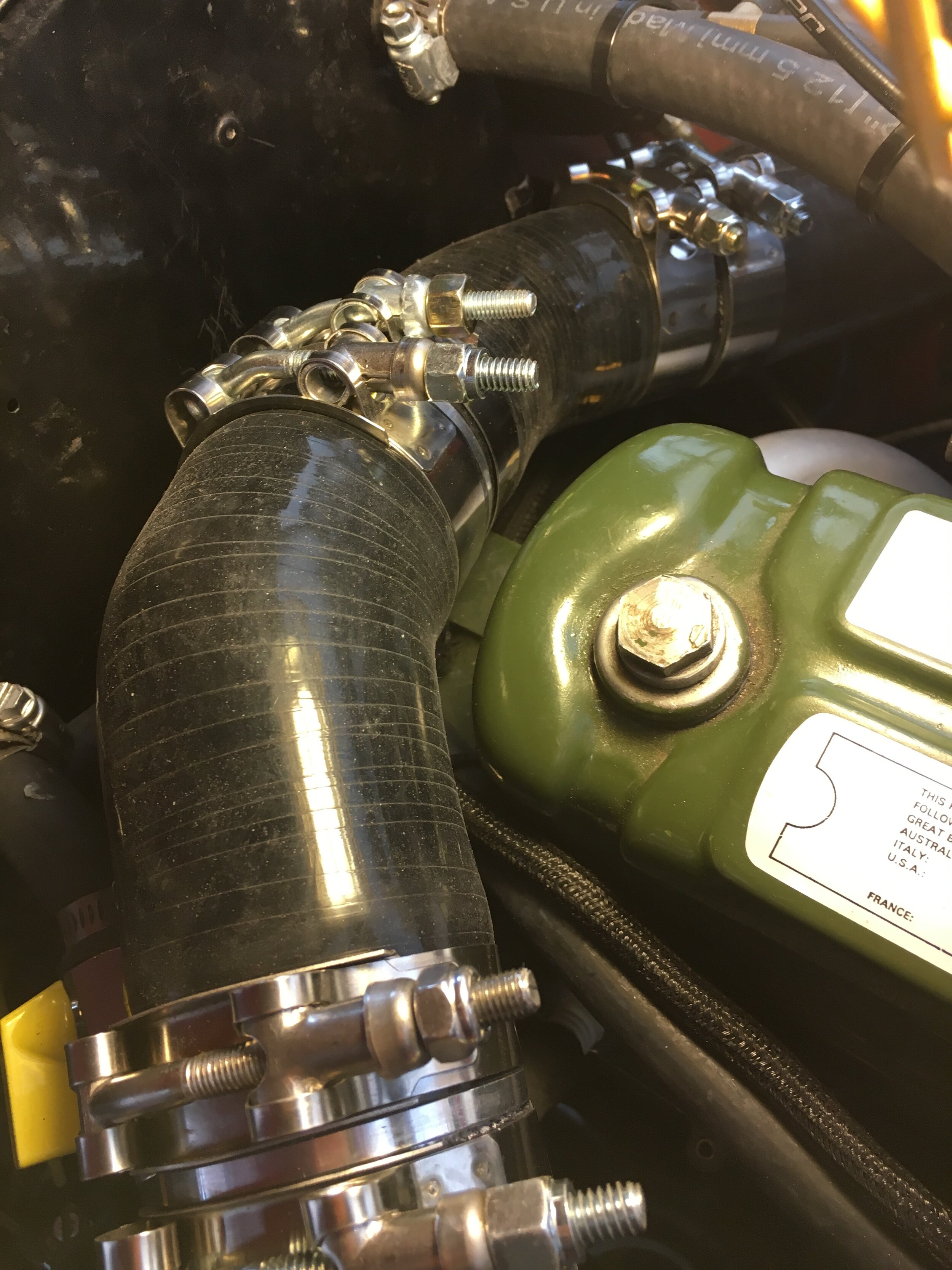
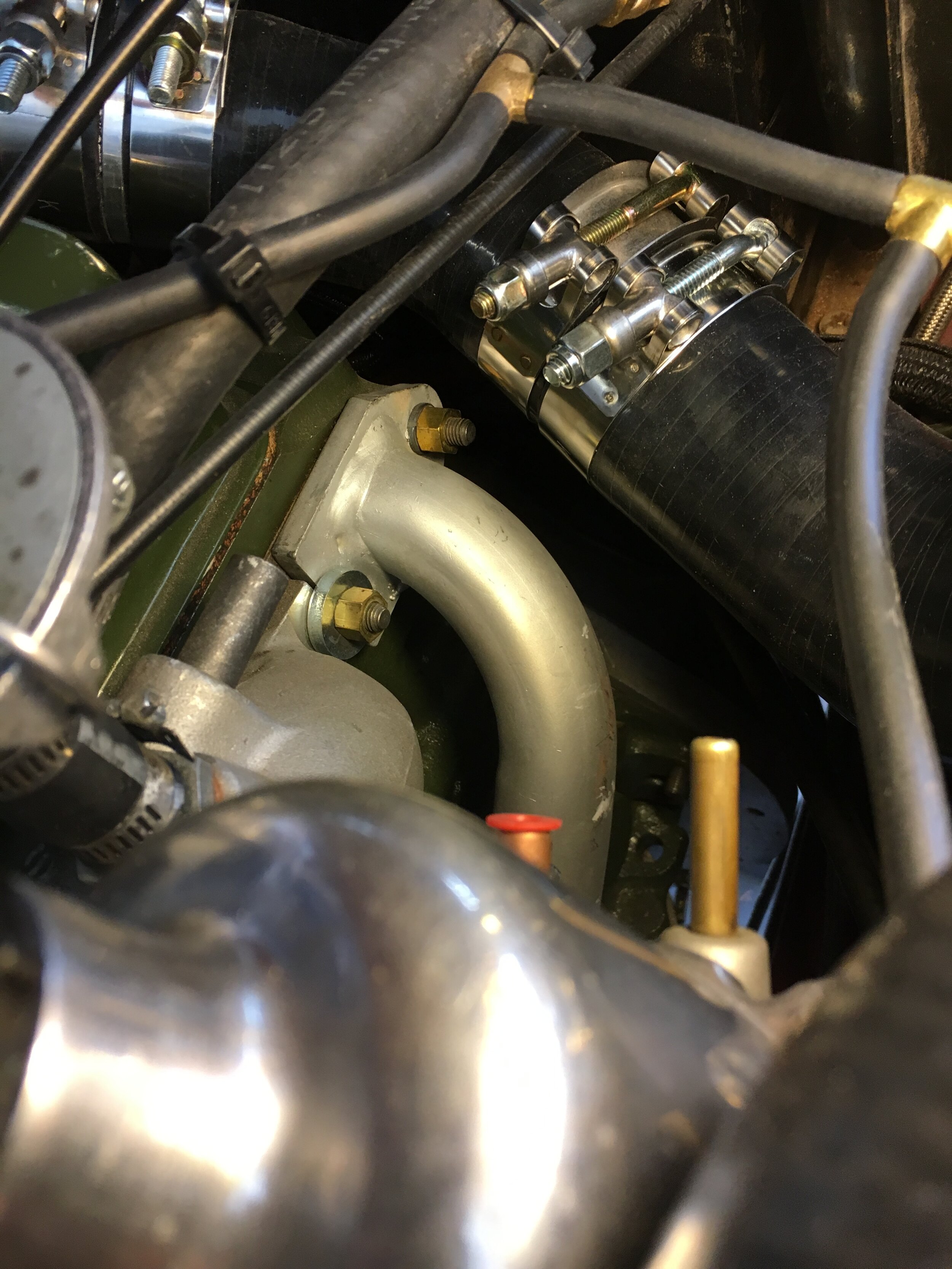
Here is a brief video discussing how the intake tract is suspended in the engine bay, and also suggesting a way to brace it if you prefer:
Modify the pcv system
The A-series engine requires a light but constant vacuum in the crankcase to prevent oil from being expelled through the rear scroll seal. The stock setup works reasonably well, but the OEM positive crankcase ventilation (PCV) valve will snap shut under boost, causing pressure in the crankcase to build.
The fix is straightforward: install a Tee or ‘Y’ fitting in the hose leading from your crankcase oil separator (or valve cover) to the existing PCV valve or carburetor nipples, and then connect the third leg to a second inline PCV valve, but oriented to close under vacuum in the manifold.
We used an inexpensive metal PCV valve (in the parts list) from a 1968 Chevrolet Impala with a 4.0L 6-cylinder engine. The smaller 3/8” end of the valve should be connected to the aluminum pipe that mates the air cleaner to the intake tract, as shown in the following slideshow.
*Note: the valve operates more reliably if oriented vertically, with its large end aimed down as shown here. If oriented horizontally or with the big end slightly up, as shown in the other (earlier) photos, the valve may stick open, drawing oil into the intake tract and creating quite a mess:
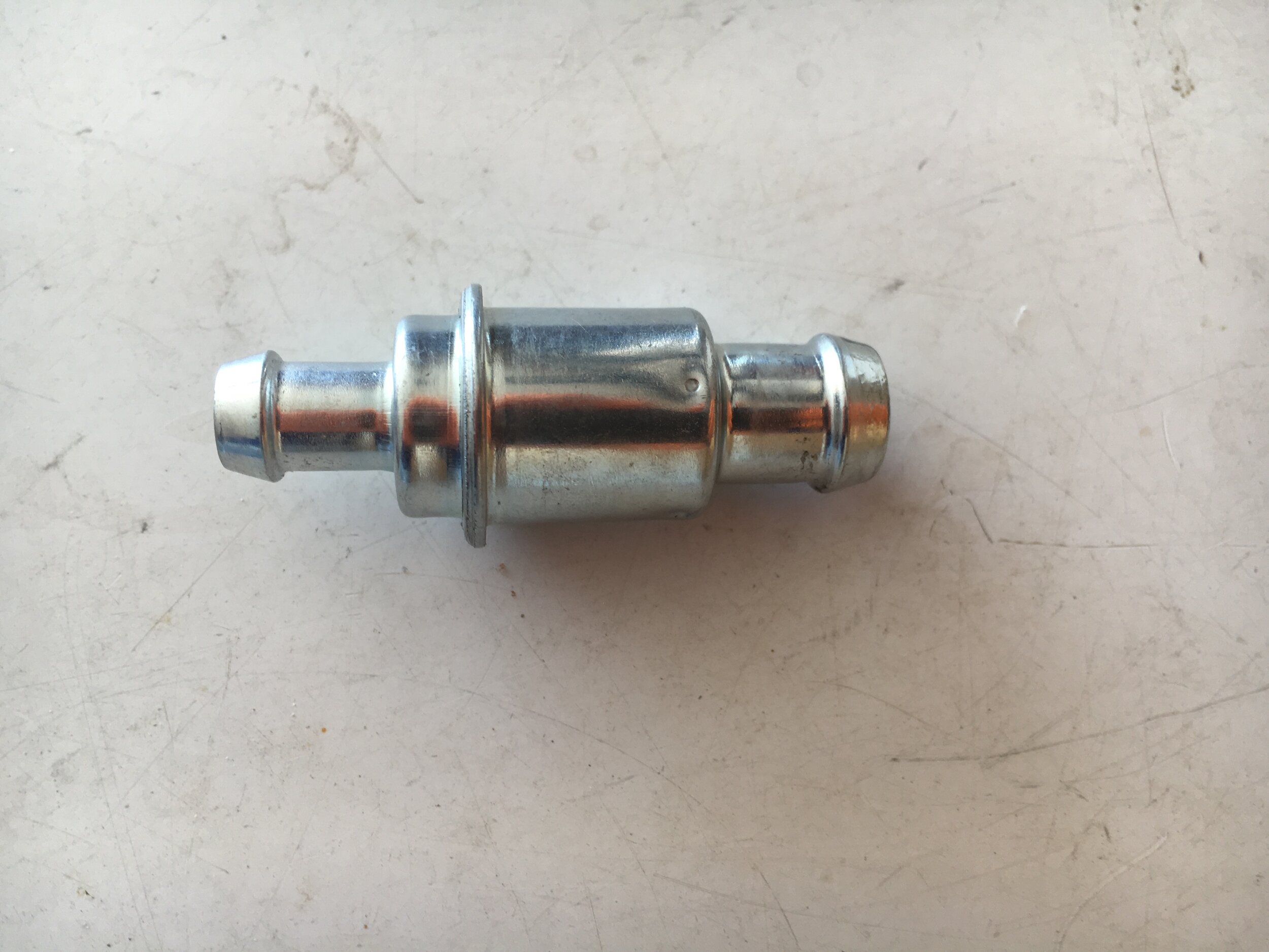
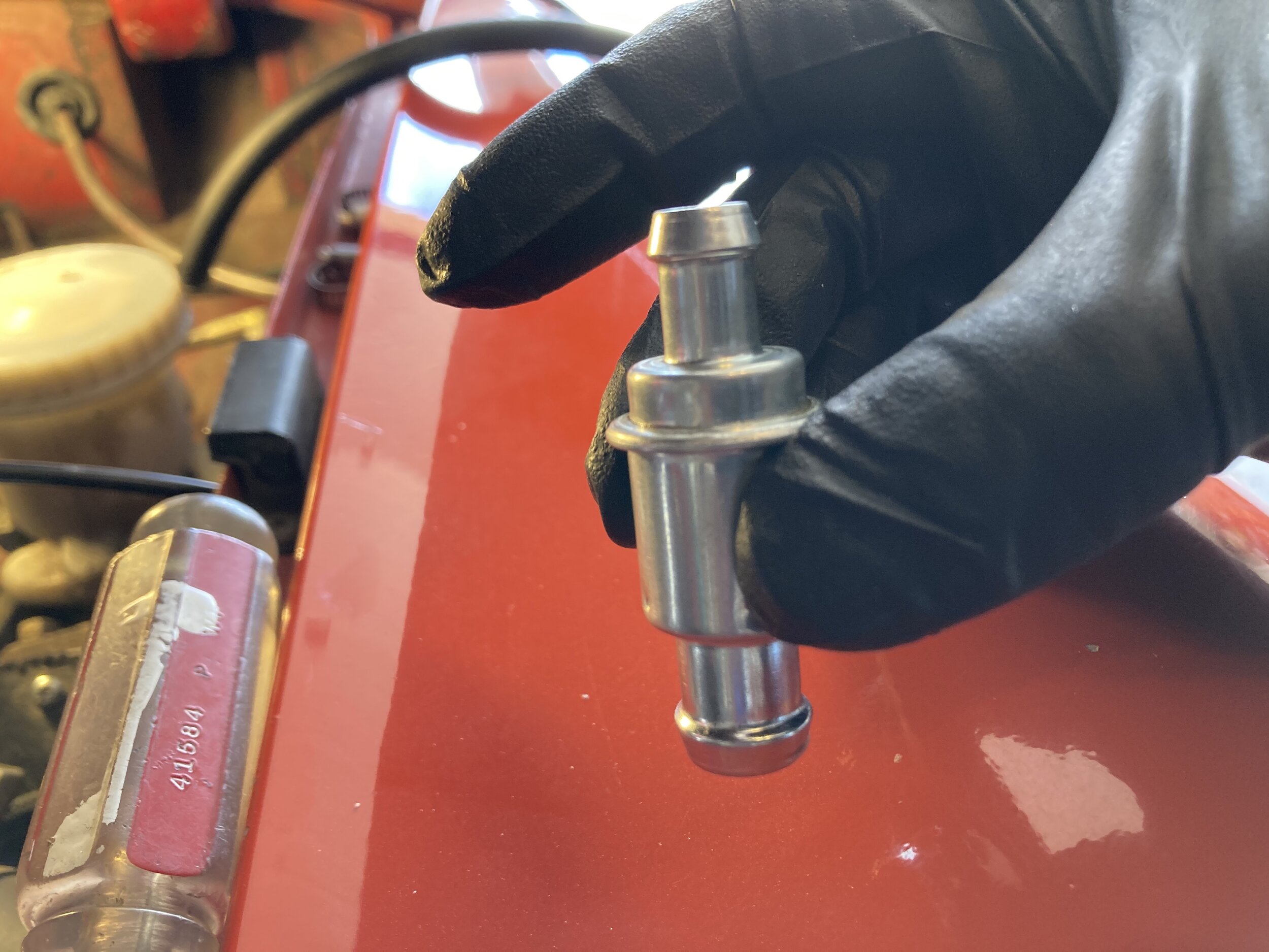
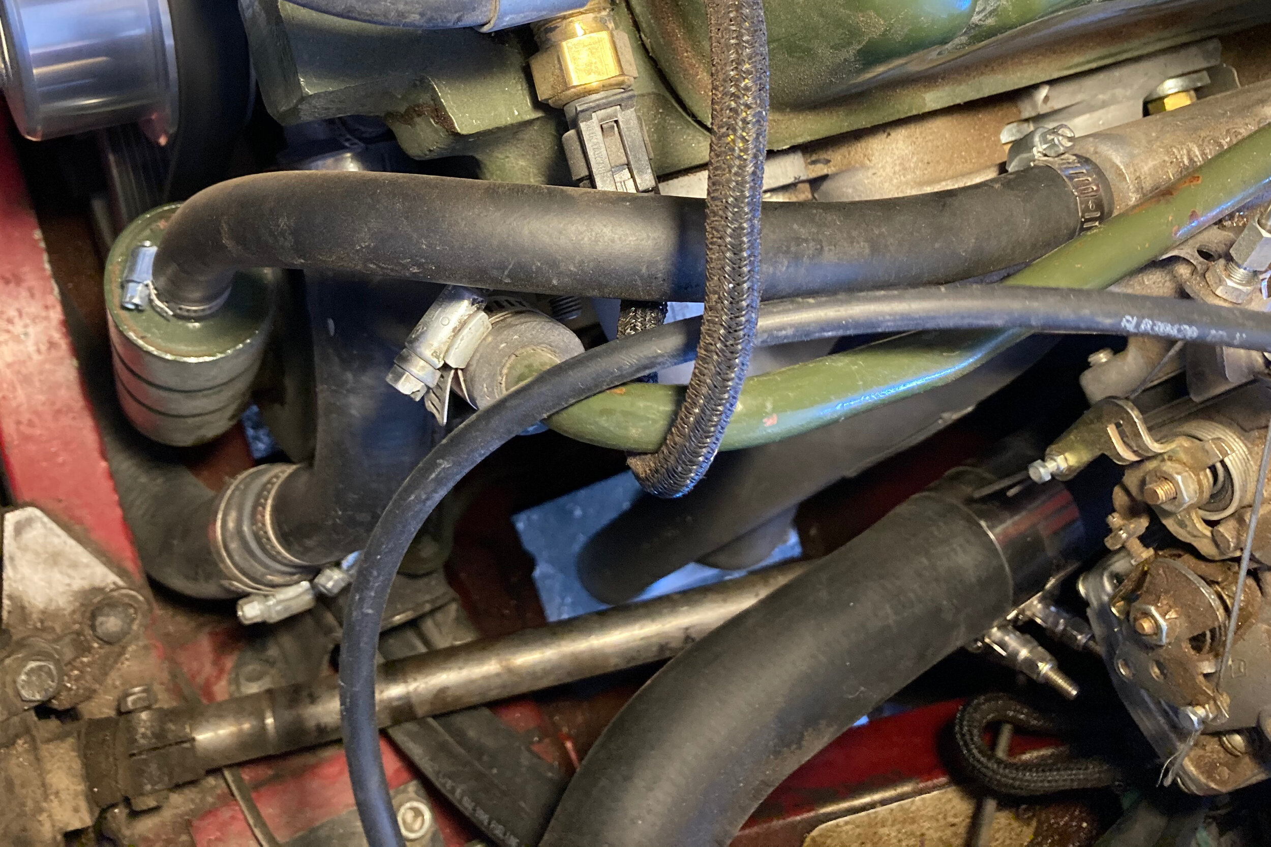
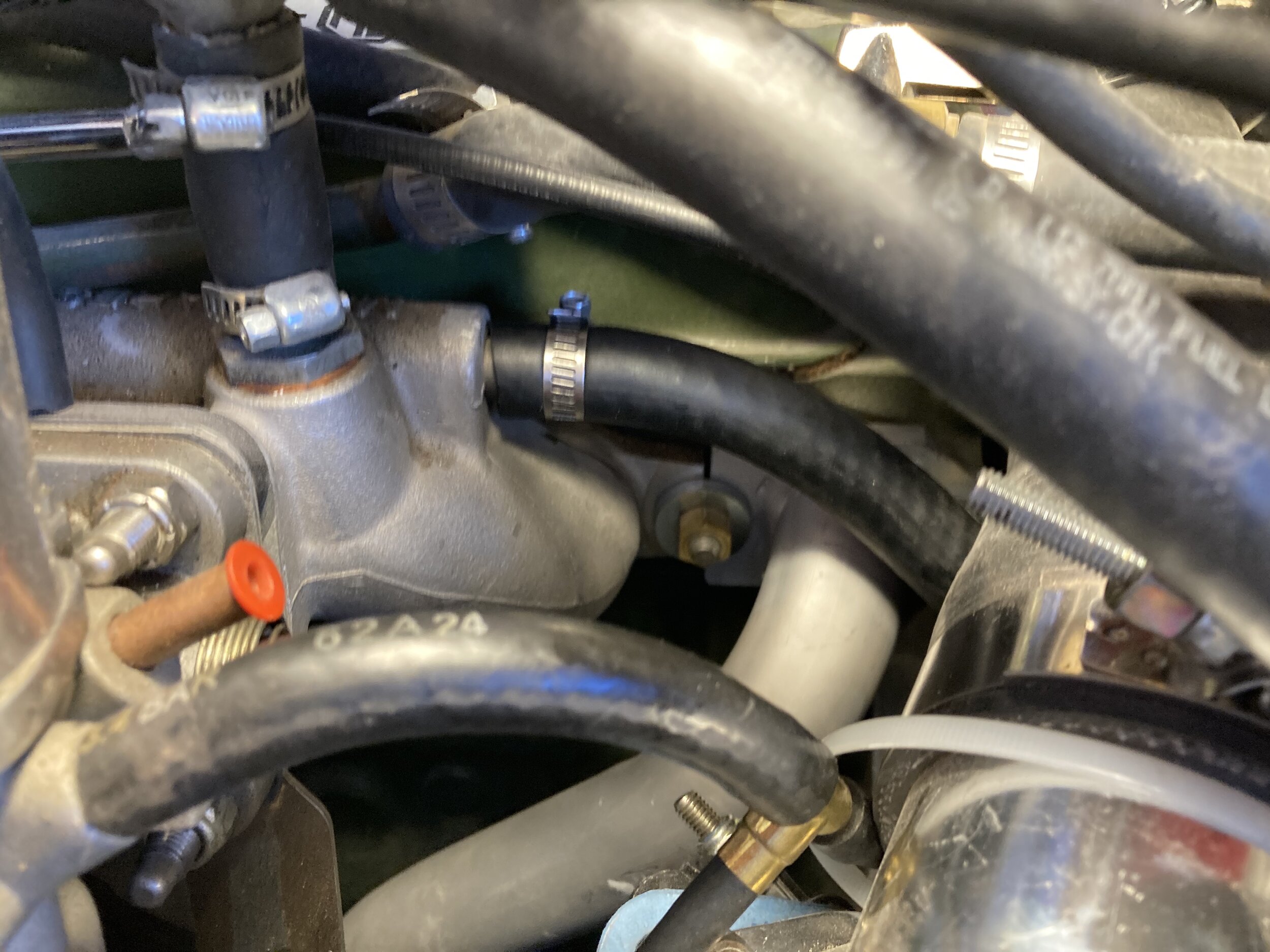
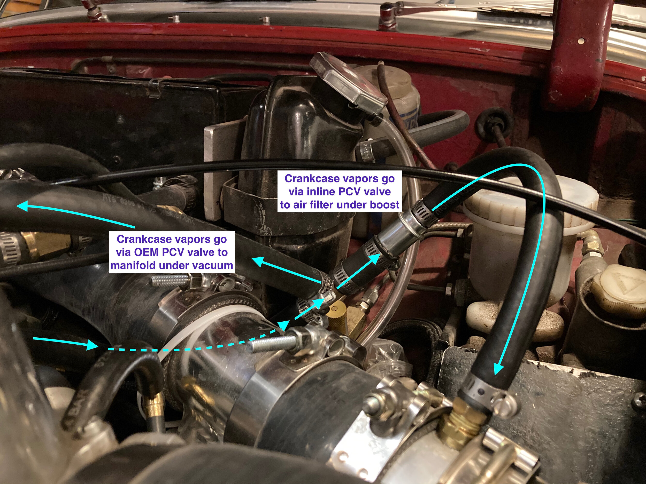
These diagrams show operation of the two-stage PCV system when the engine is running under vacuum (idling, cruising, trailing throttle) and on the boost:
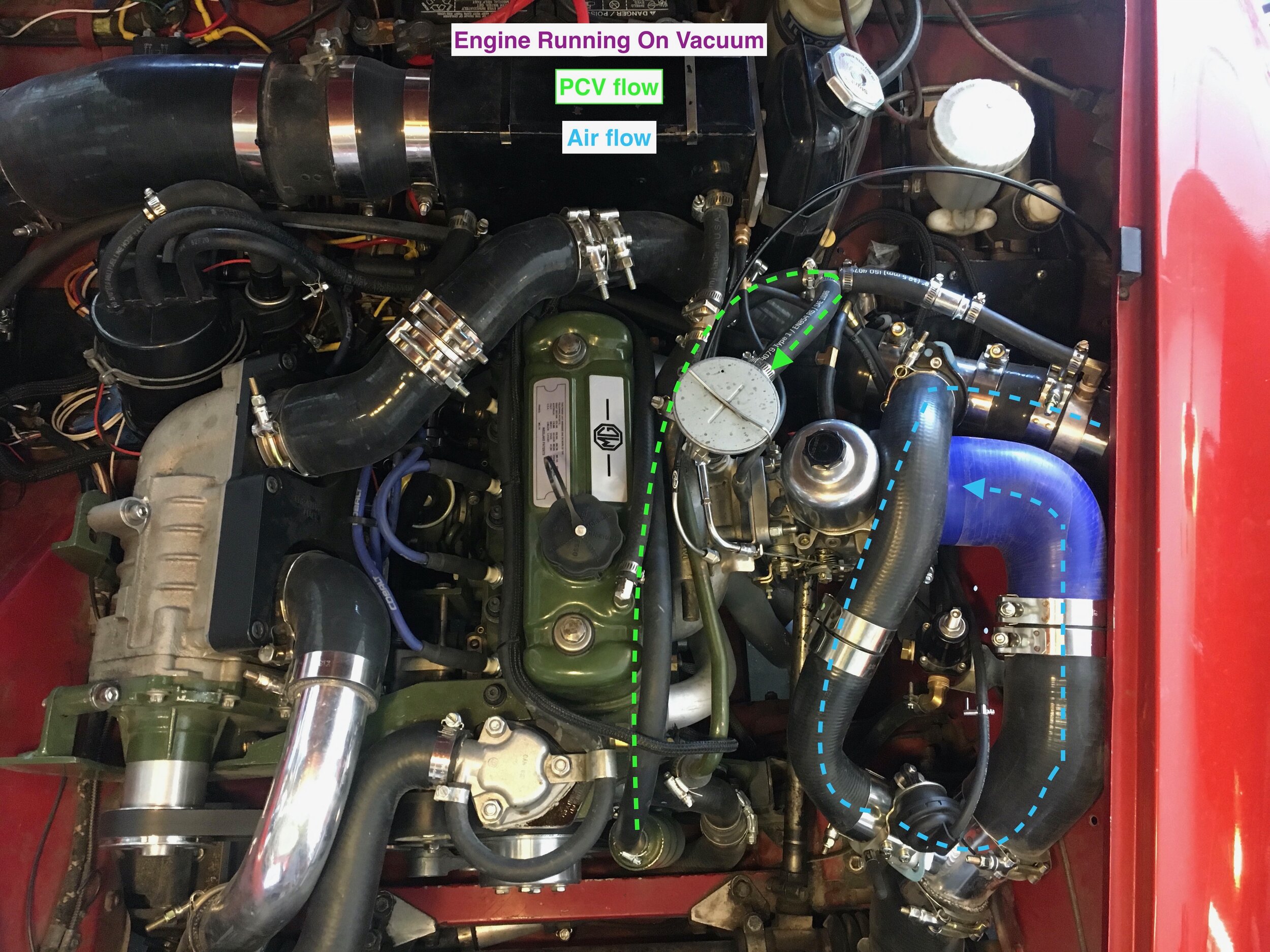

Finally, the author and our Spridget-racing friends have noticed that oil mist can accumulate on the front of the A-series engine after sustained runs at speed (i.e., at 4,000~5,000 rpms and above). One racer attributes the phenomenon to a weeping 1/2” heater hose, which is not designed to resist oil.
However, additional contributing factors are that the oil separator’s pipe tapers slightly toward its terminus and lacks a barb.
We solved this issue with a little masking tape, inexpensive JB Weld, light sanding, and OEM engine paint. Gravity made the steel-reinforced epoxy sag slightly during the cure over night, ironically producing an effective barb profile (we removed the tape quickly after applying the epoxy; it did not stay on over night).
Now the hose stays put and seals well, even without a hose clamp—though we recommend using one:
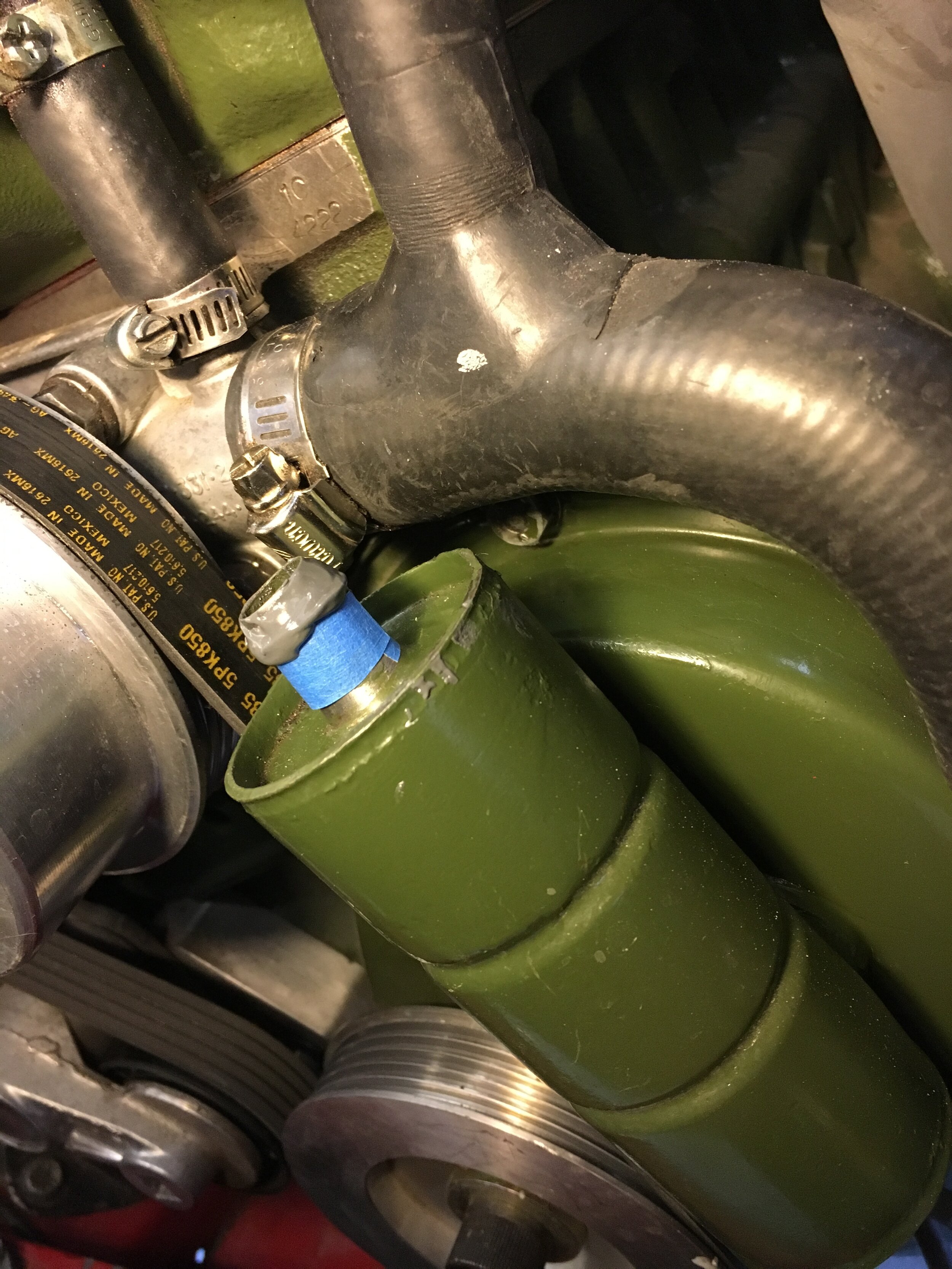
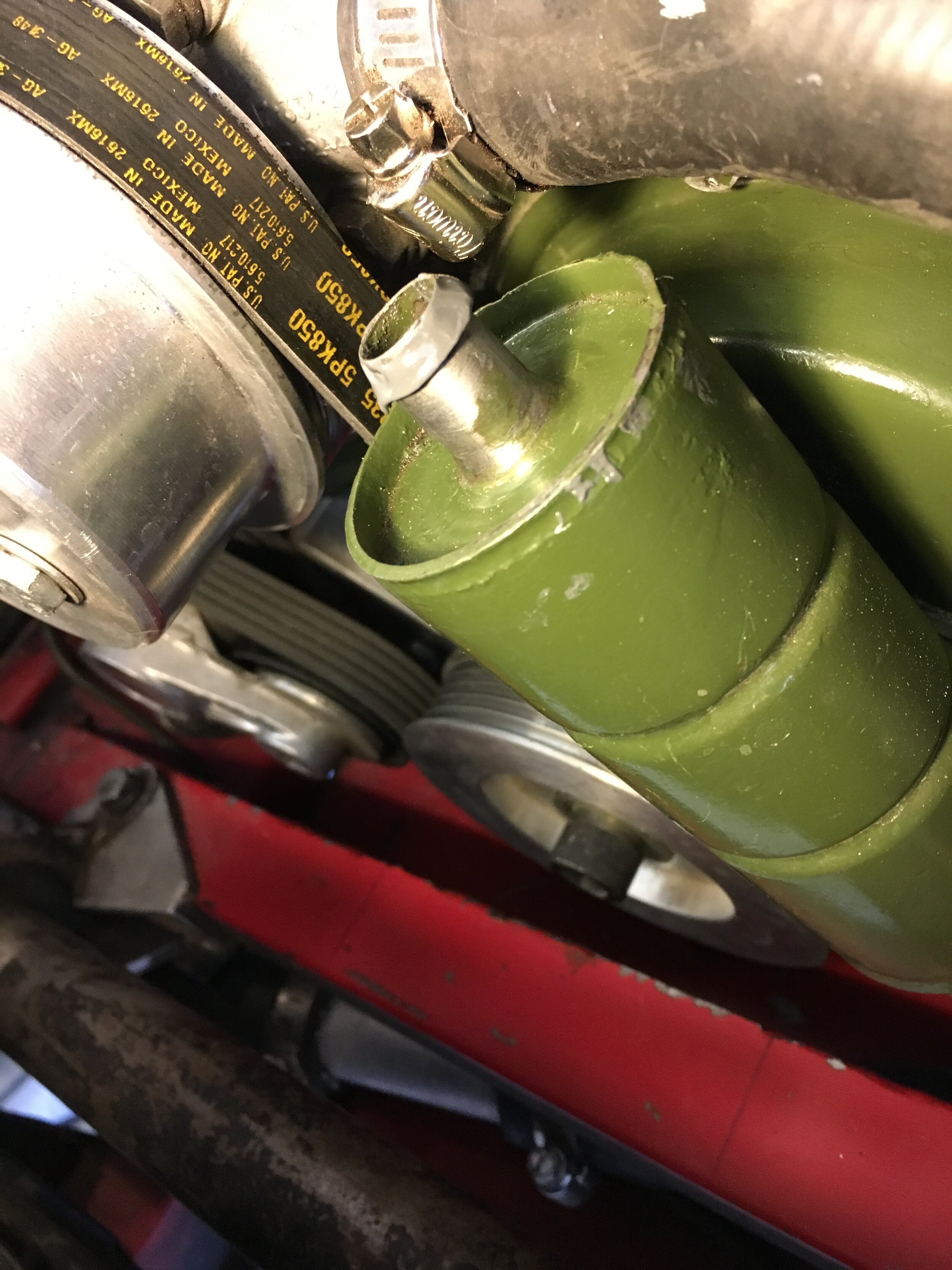
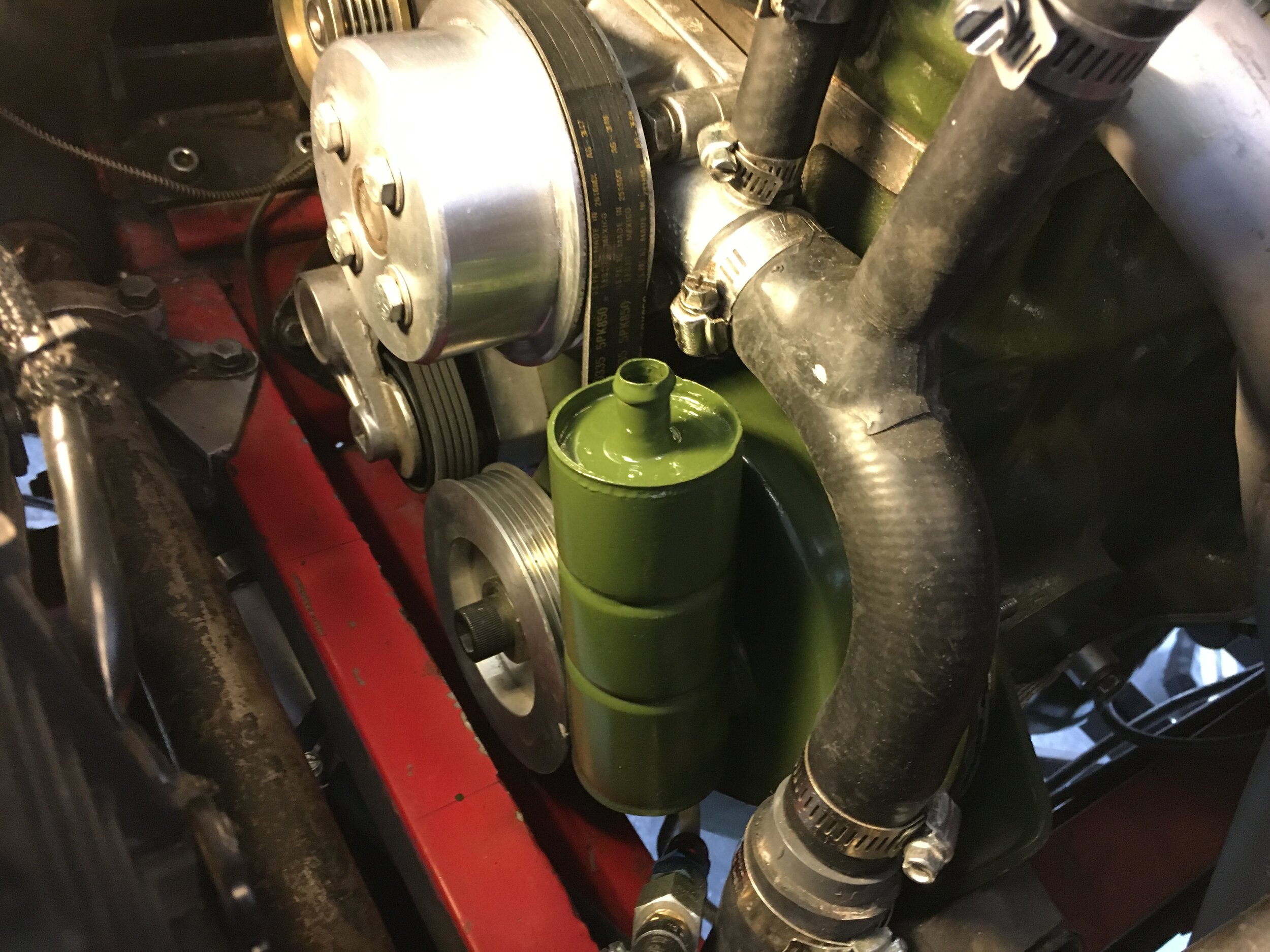
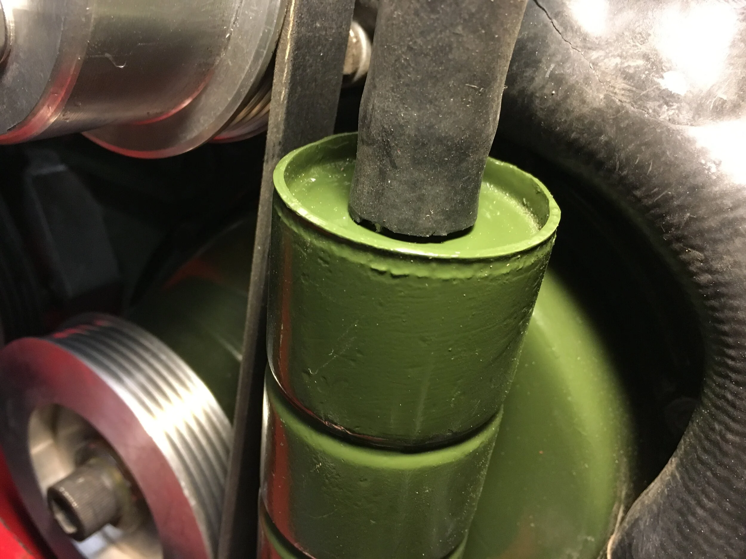
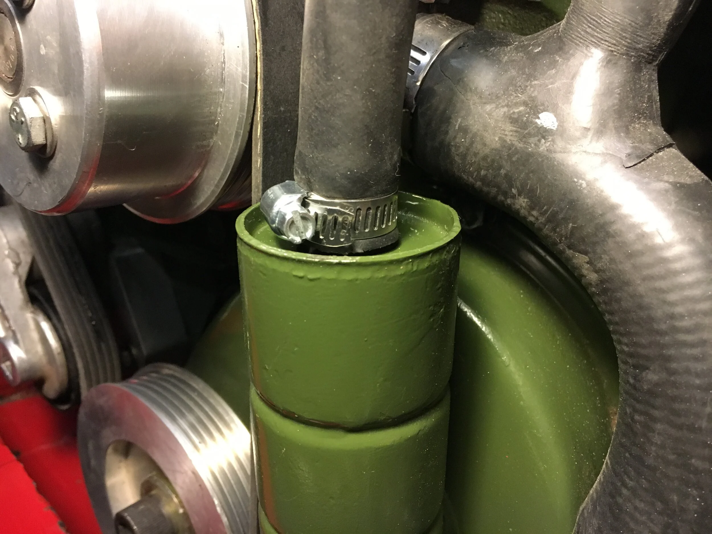
prepare the carburetor
The standard (non-turbo) SU HIF44 is readily converted to run under boost, as set forth in this section. However, some Spridgets will encounter slight contact between the sloping bonnet and the dashpot cap. There are two solutions.
The first dashpot clearance solution is to replace the standard cap and damper rod with a low profile version, SU part no. CUD2901, shown side by side with a standard cap and rod for comparison:

This should create sufficient clearance for the bonnet to safely close. However, to avoid dimpling the sheet metal, you should confirm clearance by placing a little ball of Play Doh or similar modeling compound atop the dashpot cap and gently lowering the bonnet.
Note that the metal clip on the damper rod has no function in this application and may be removed. We grabbed it in a vise and cut it with a Dremel, then twisted a flat blade screwdriver to break the clip off without damaging the rod:

Using the shorter cap will limit upward travel of the vacuum piston and needle by approximately 2mm, thus slightly limiting wide open throttle (WOT) operation, although the carburetor’s function is not otherwise affected. The damper rod may be shortened to eliminate this, though care must be taken to ensure the rod is aligned properly when reinserted into the cap and does not cause the piston to bind. Ultimately, the effect on performance is probably indiscernible with a forced-induction system and attempting this modification may cause more issues than it resolves.
The second dashpot clearance solution is to use a different manifold.
One possible option is the Titan Motorsport manifold. Here is an image showing the Titan’s reduced flange angle and lower centerline on the carburetor flange:

Another solution is the Maniflow L159 manifold, which the company confirmed sits “level horizontal” and should thus afford much more vertical clearance than the C-AHT770 Minispares manifold shown throughout these instructions.
However, we are waiting word from Maniflow regarding the lateral distance between the head and carburetor flange, to ensure adequate room for the 90-degree snorkel feeding the carburetor:

The Maniflow L159 may be ordered with a vacuum servo takeoff to retain the stock PCV system, and is available direct from the UK for $198 plus shipping, or from $261 to $330 in the U.S. (IM48-20, C-AHT669, or C-AHT770M).
Yet another possibility is the Fletcher casting, but we have yet to locate one.
A final clearance issue may exist between the carburetor throttle linkage and the manifold, depending on which car was the donor for your HIF44.
There are several kinds of throttle linkage used on different iterations of the HIF44. However, the linkage, cable stop plate, and phenolic spacer in the following photographs are one proven option in case your parts do not clear your manifold. Let us know of cheaper sources, as these vendors are expensive:
Linkage plate - Seven Classic Mini Parts, no. FOR021:

Here is how the cables attach to the above steel plate:
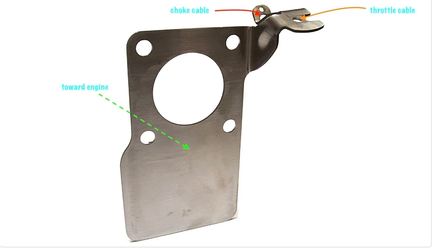
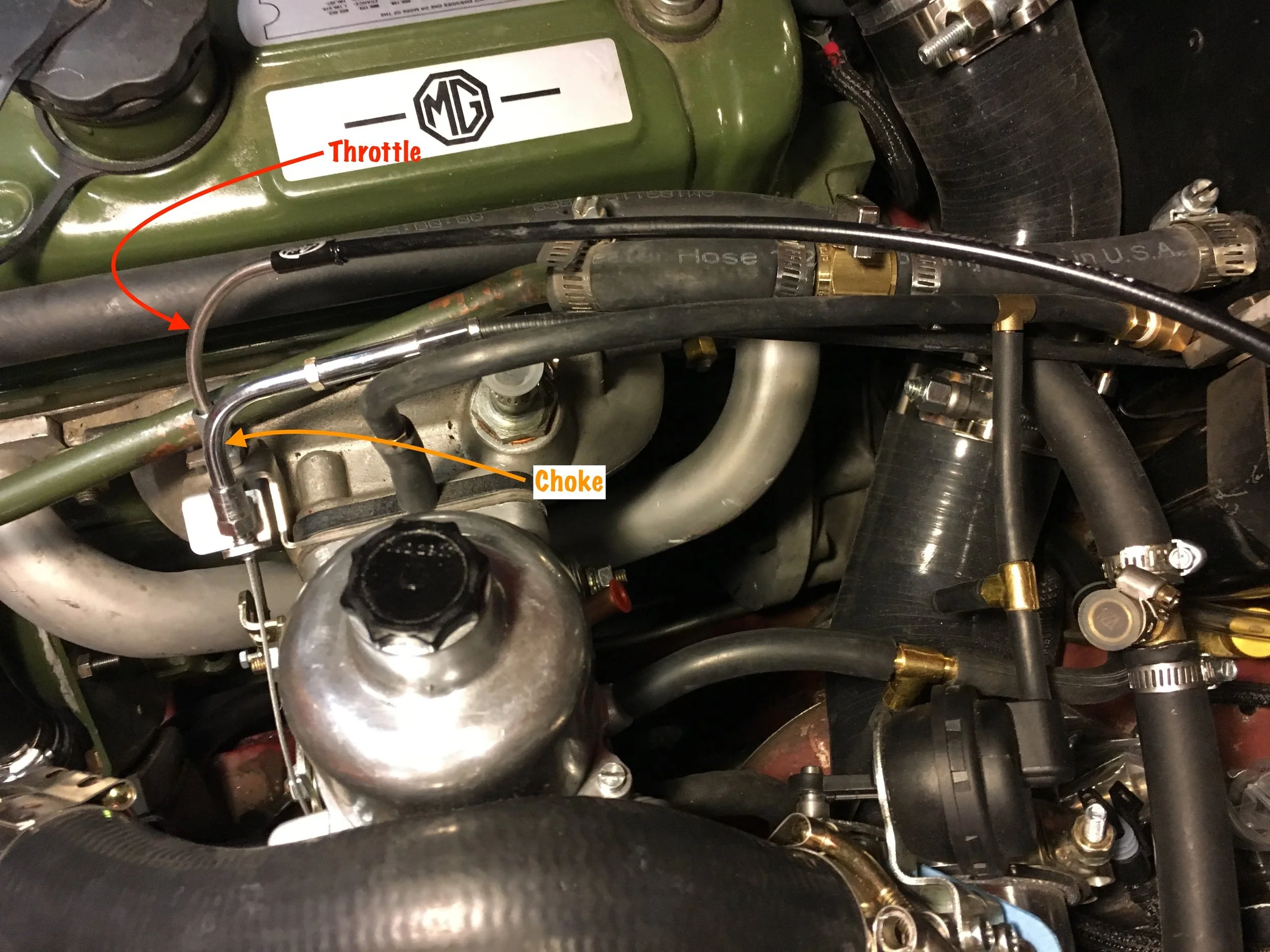
Throttle arm linkage - Mini Mania, no. JZX1603:

Phenolic spacer - Seven Classic Mini Parts, no. MFA446:

Now, on to preparing the carburetor to operate under boost!
STEP 1 - Reverse the throttle shaft seals
The MG Metro-spec HIF44 uses the same throttle butterfly shaft as the standard-spec carburetor used in this conversion, and the same seals. The only modification necessary is to flip the seals, such that their lip faces inward to seal against boost rather than vacuum, as shown in this picture:
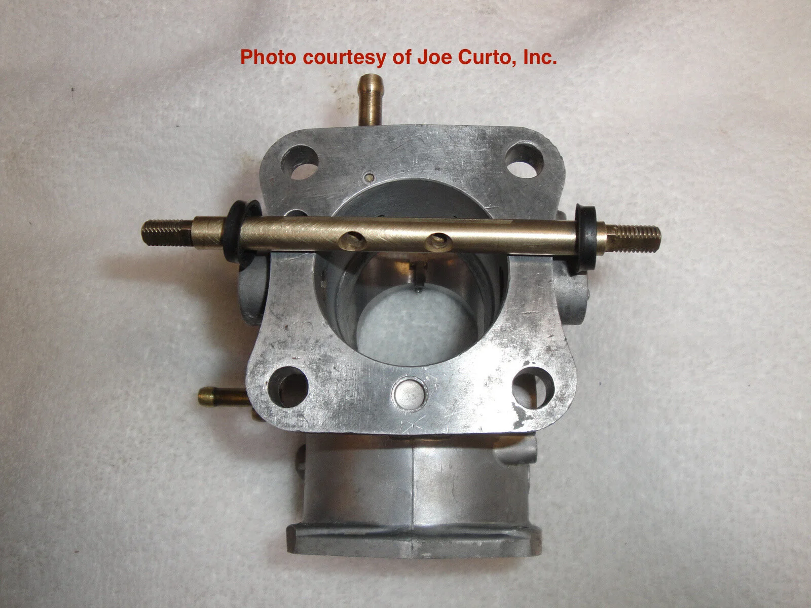
This photo series will guide you through the process of inverting the seals.
First, remove the vacuum chamber and piston. If you carefully remove the chamber, spring, and piston together, and set them on a convenient surface that will protect the needle, you need not drain the damper oil:
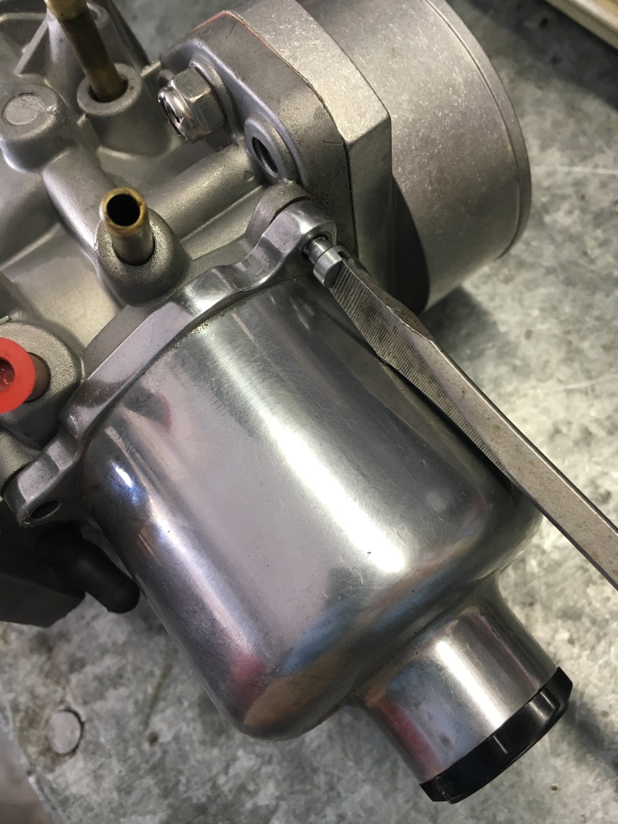

Second, use a small flat-blade screwdriver and a small drift to bent down the locking tabs on the forward side of the throttle shaft—where the cable attaches:

Third, before you remove the throttle lever, note how the ends of the spring contact the carburetor body and tab on the throttle lever. The spring will unwind approximately one turn when you remove the lever:
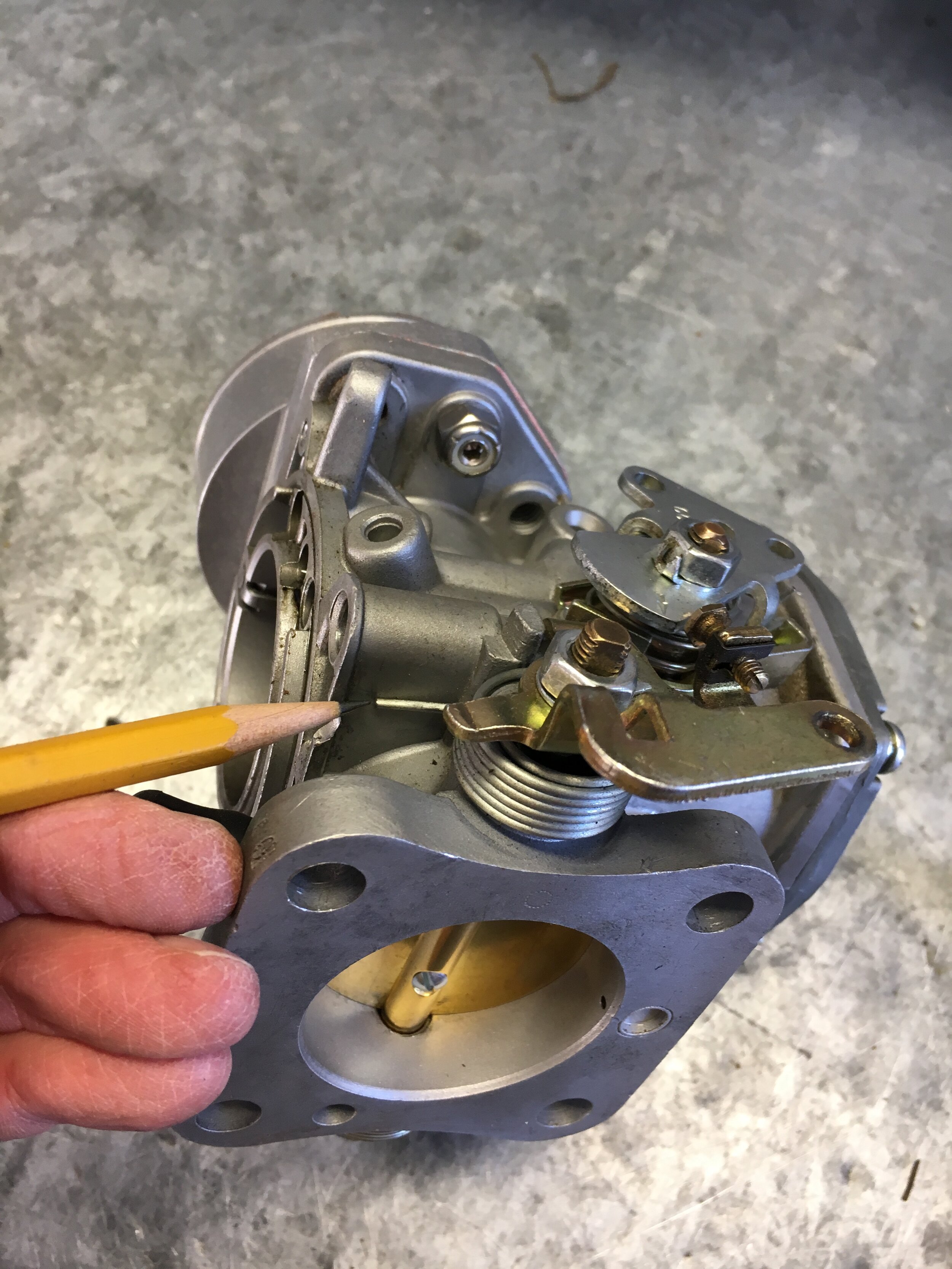
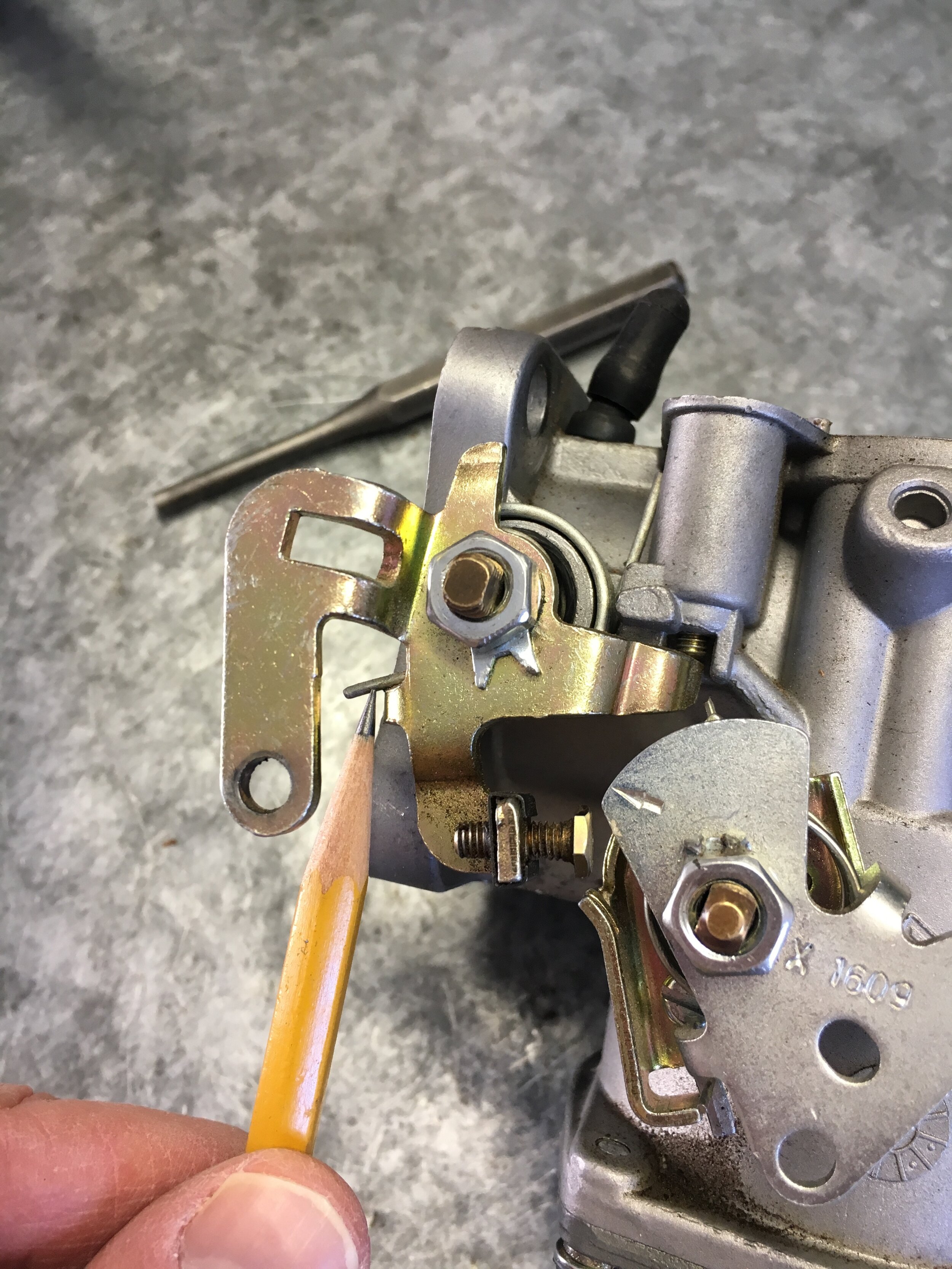
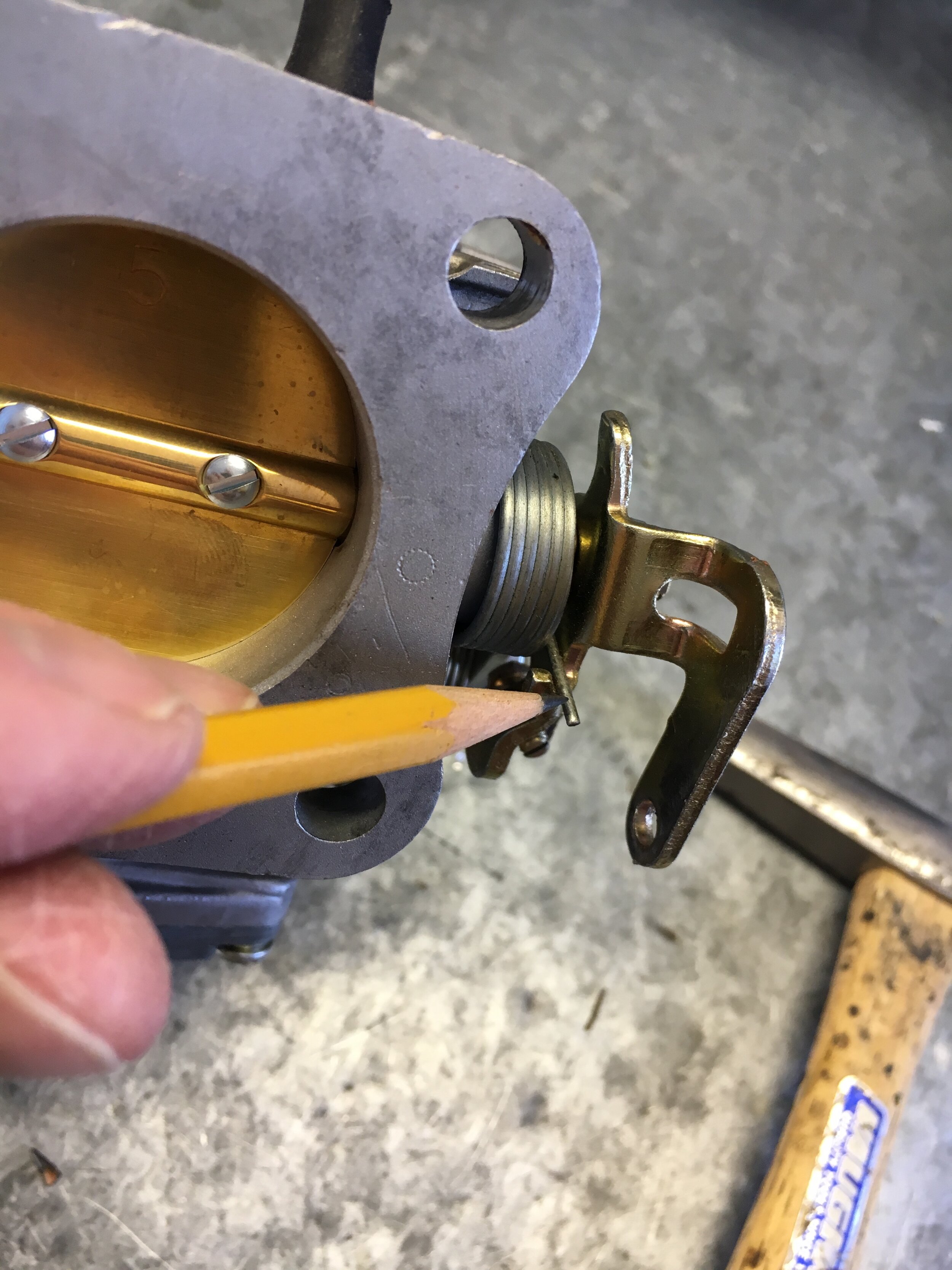
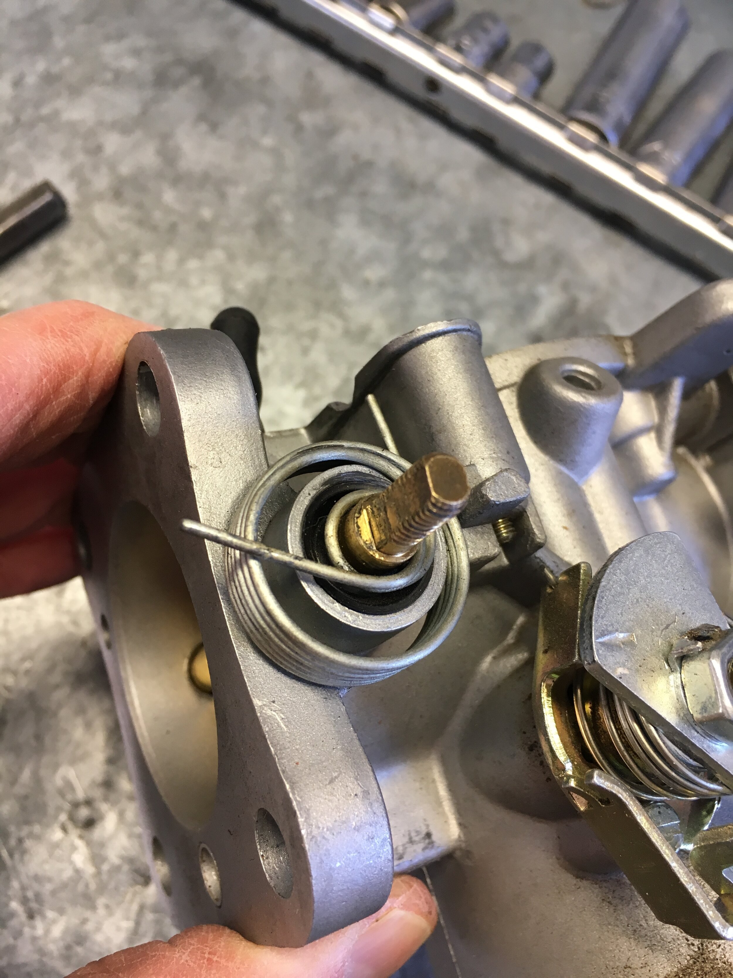
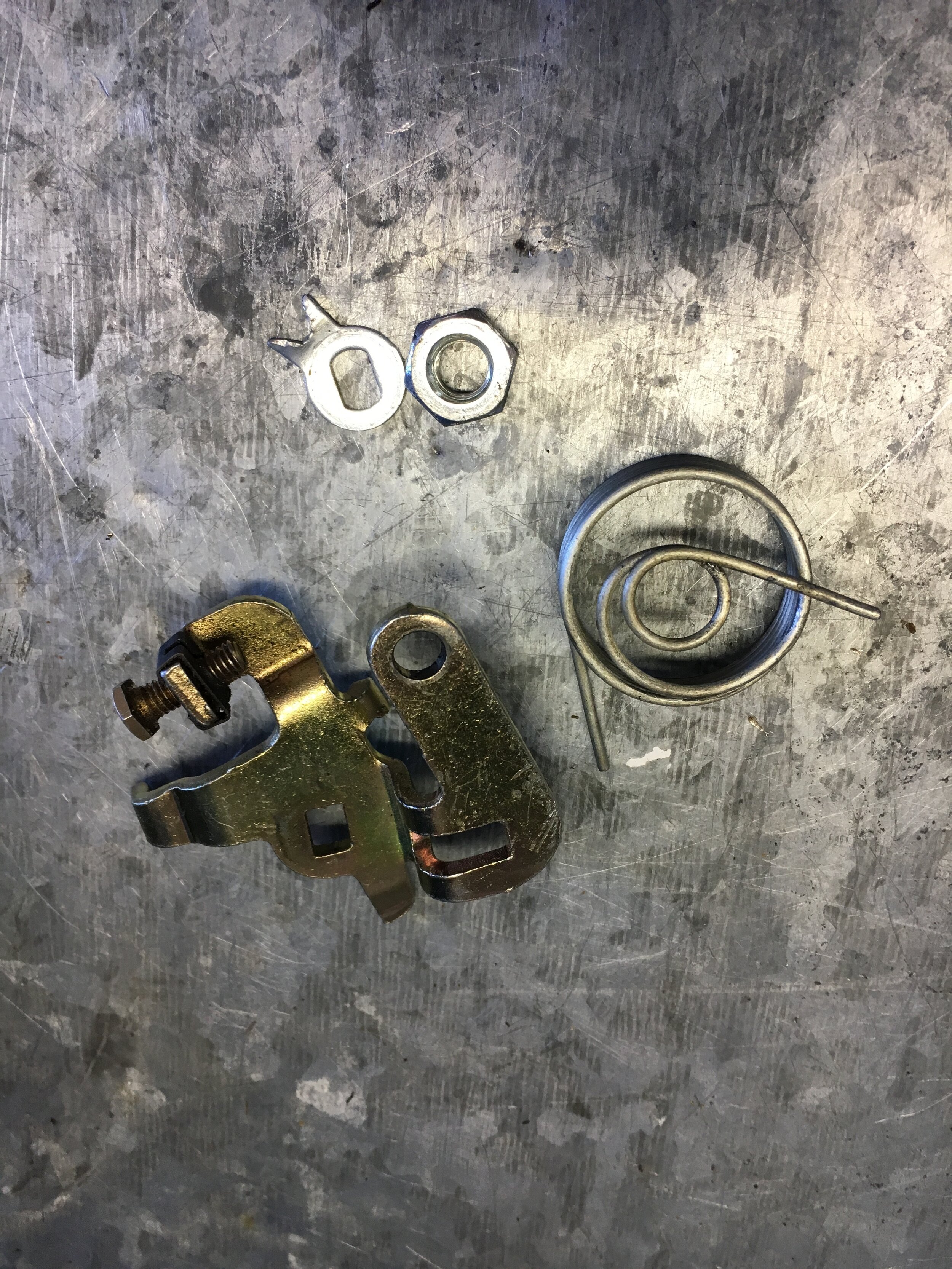
With the lever and spring out of the way, you can see the seal in its normal orientation, with the sealing lip facing outward toward you:

Fourth, flip the carburetor over and, once again, note how the spring contacts the short return lever and carburetor body before removing the lever:
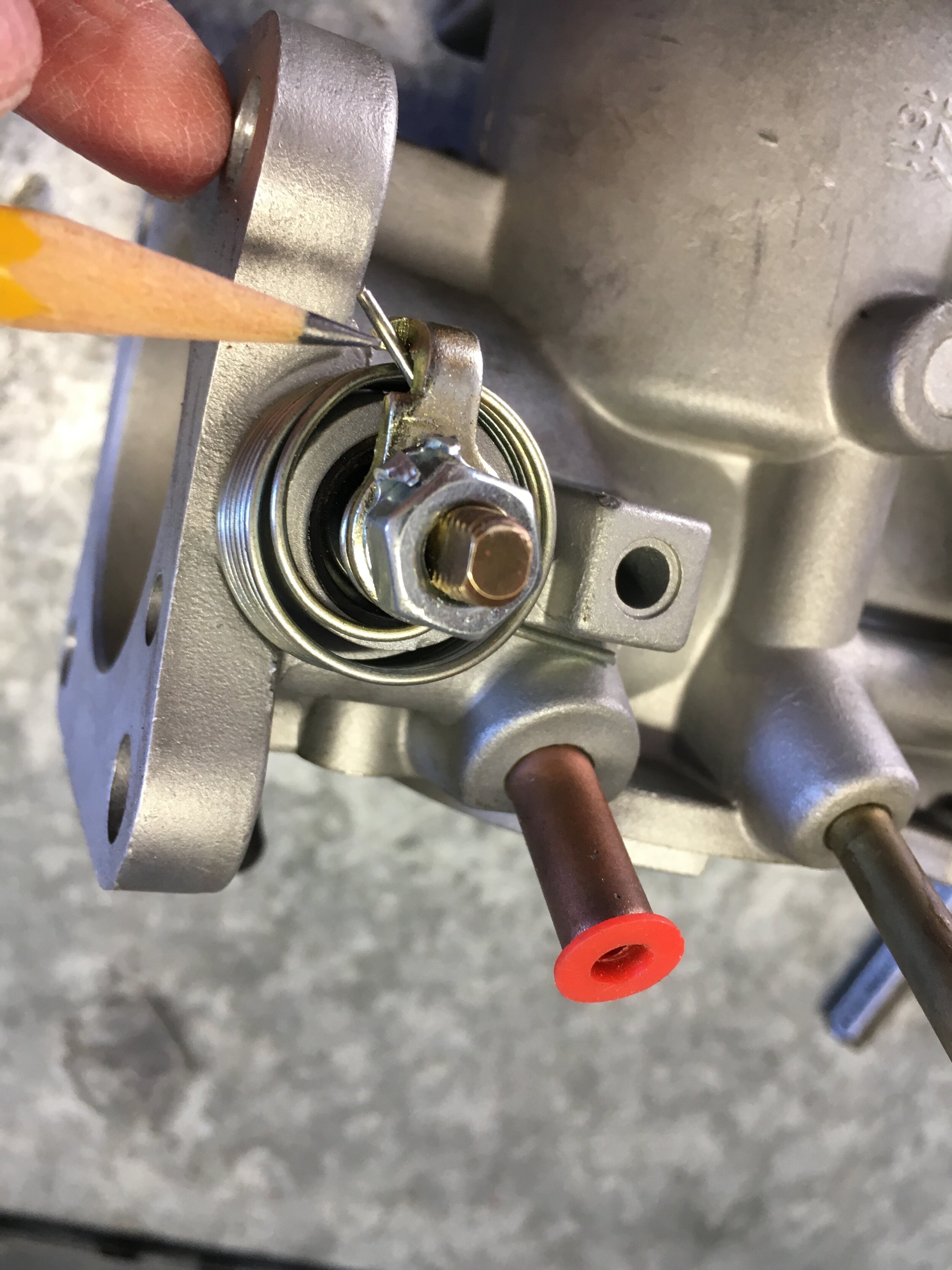
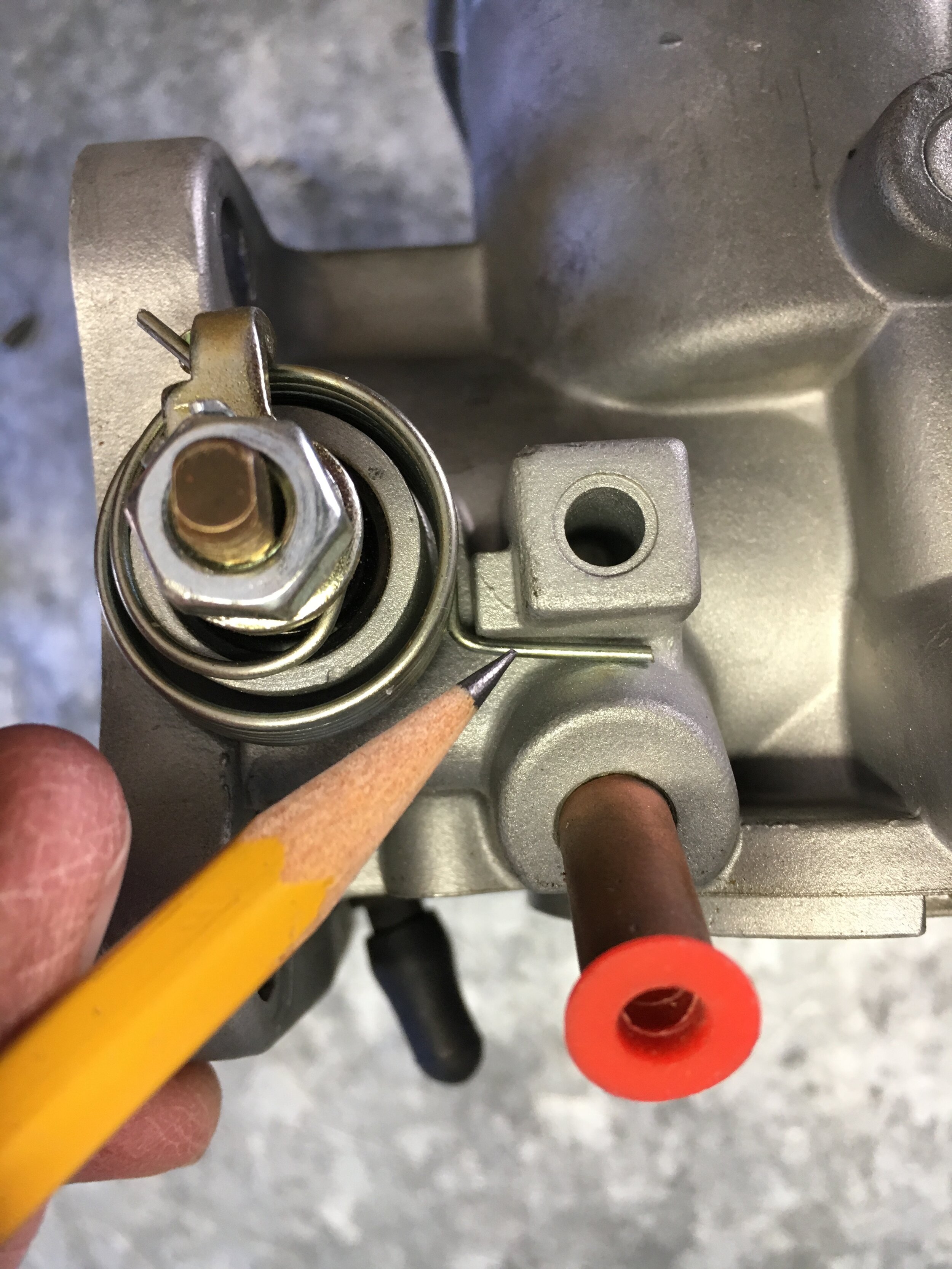
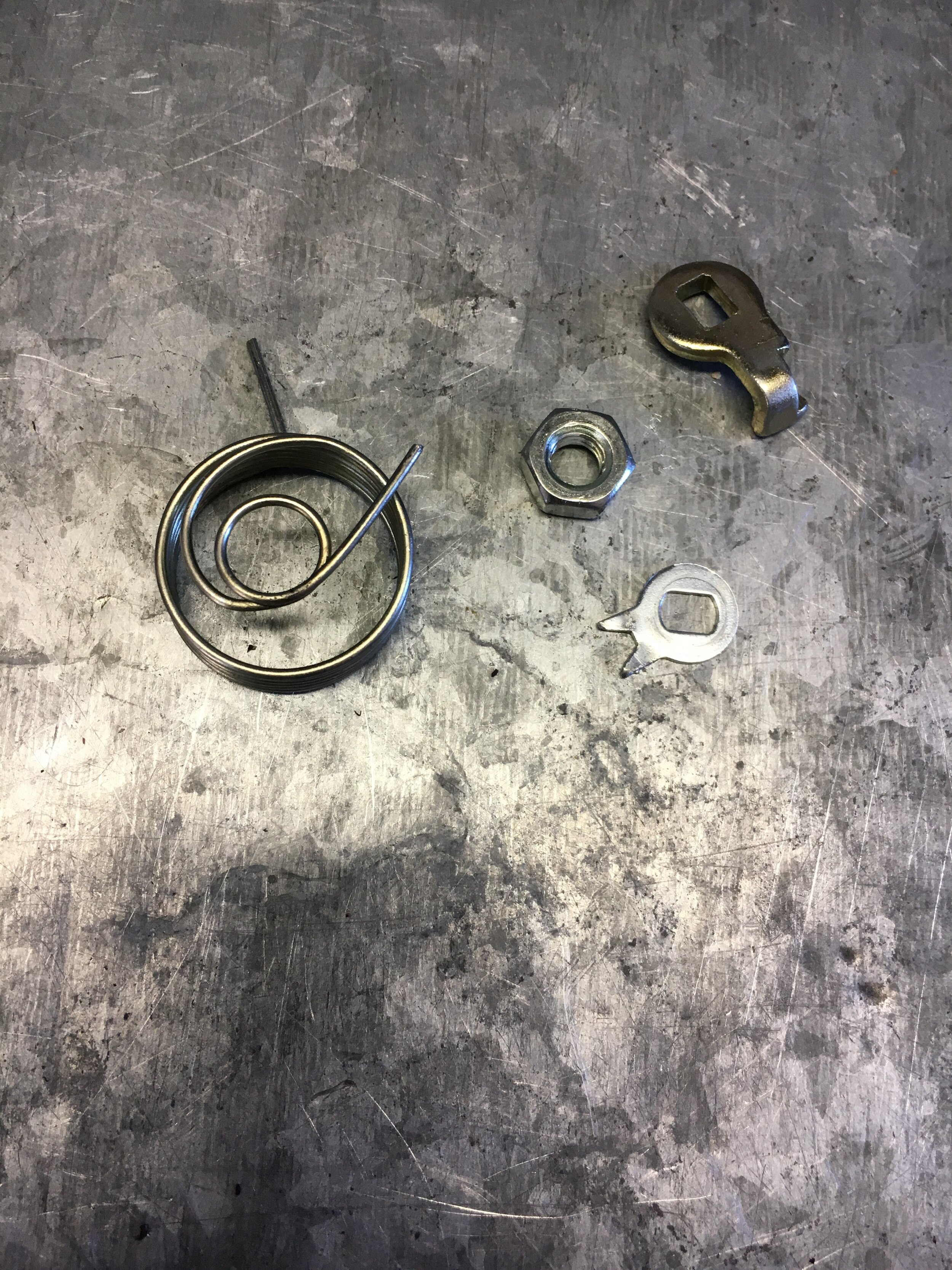
Before removing the throttle butterfly, note that there may be a stamped number on the top inward side (toward the manifold). If not, make a mark here so that you replace it in the same orientation (the other marks are from a pencil):
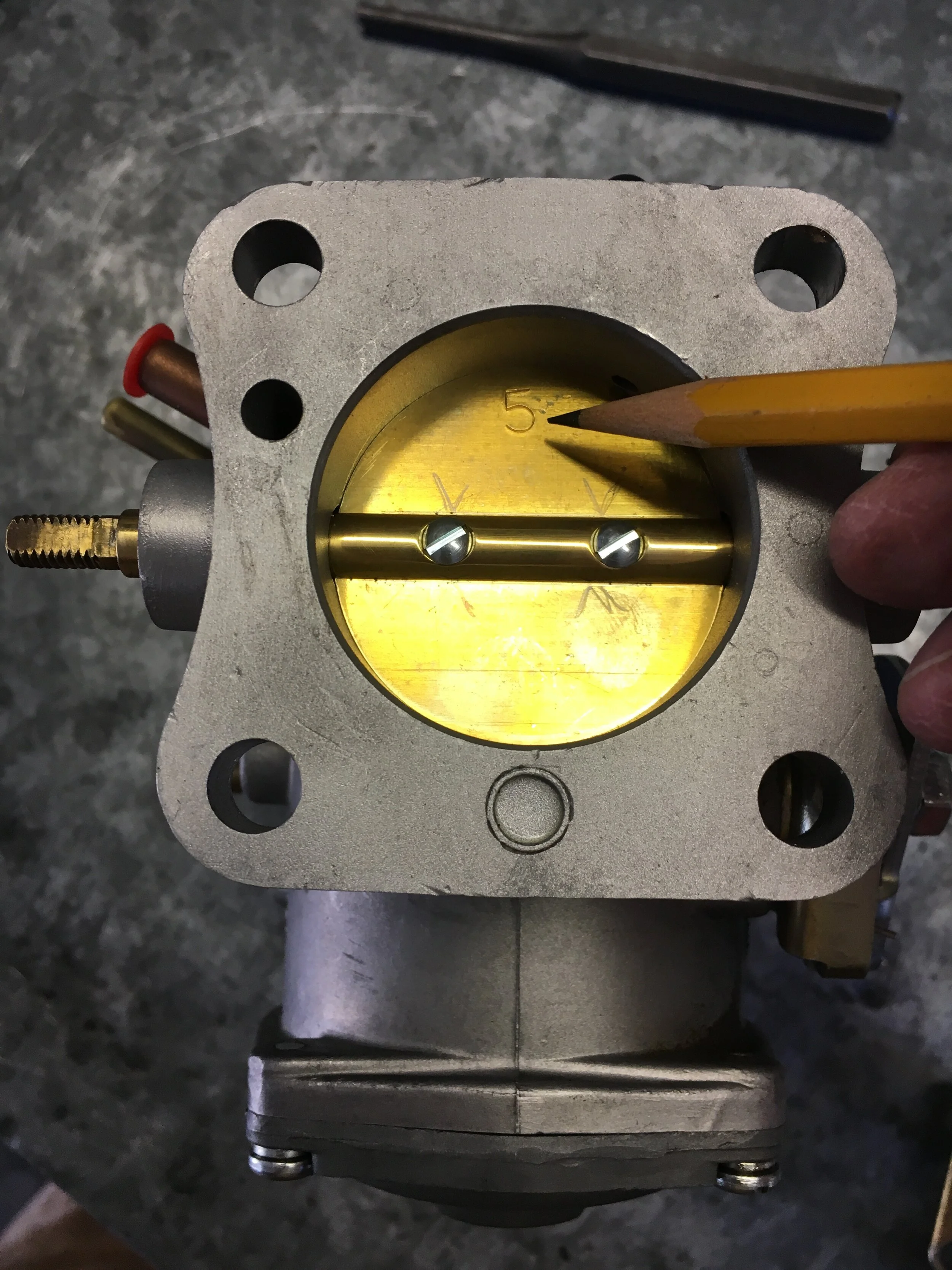
Fifth, open the throttle butterfly to examine the other end of the screws. This may require you to slip back on the lever or tap gently on the top of the butterfly. (Where the stamped number is in the above photo.)
You will note that the screws have slots to allow you to splay them slightly upon reassembly, so they won’t work lose and get sucked into the engine:

Sixth, remove the screws and discard them, then withdraw the butterfly:
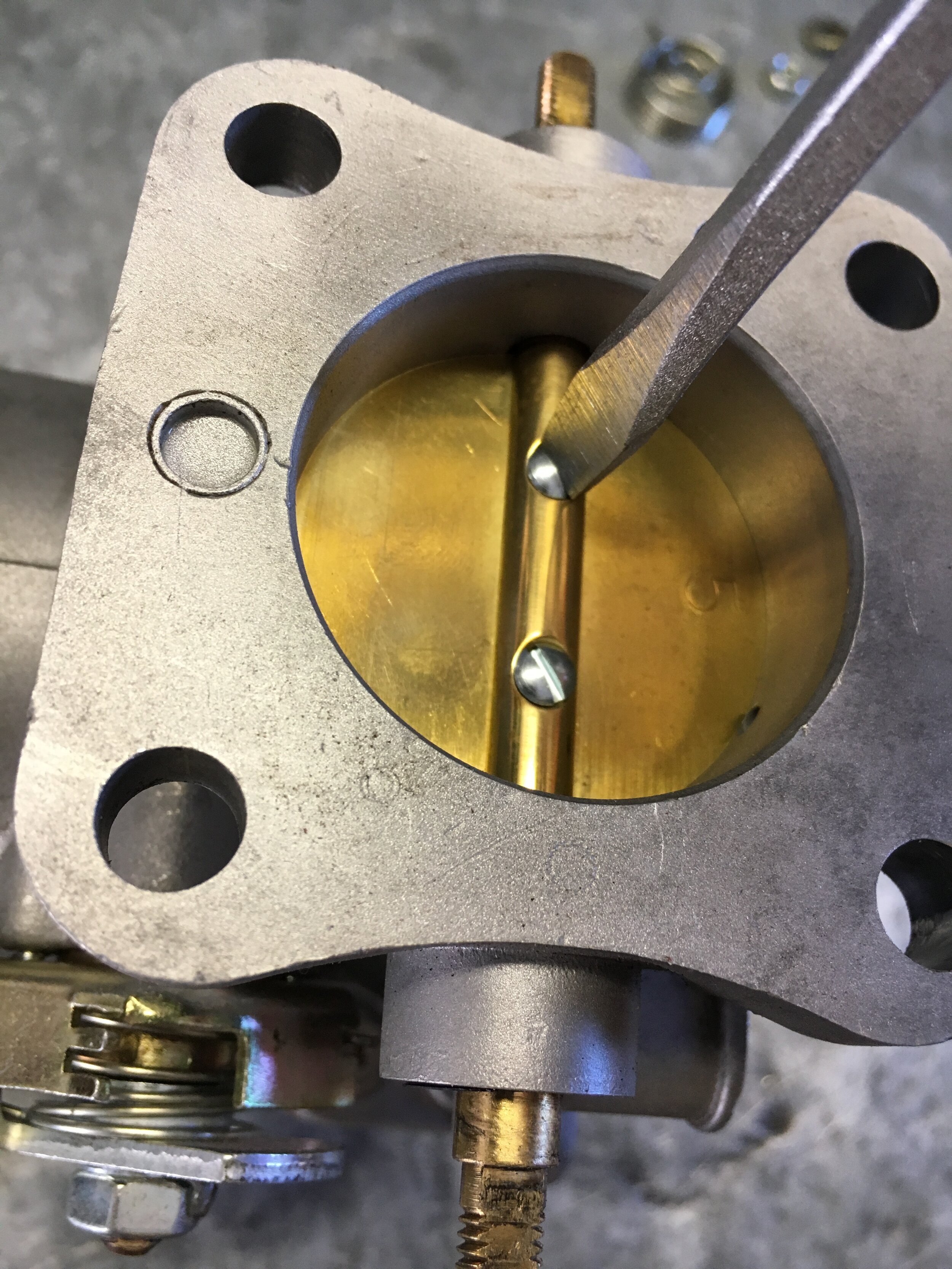
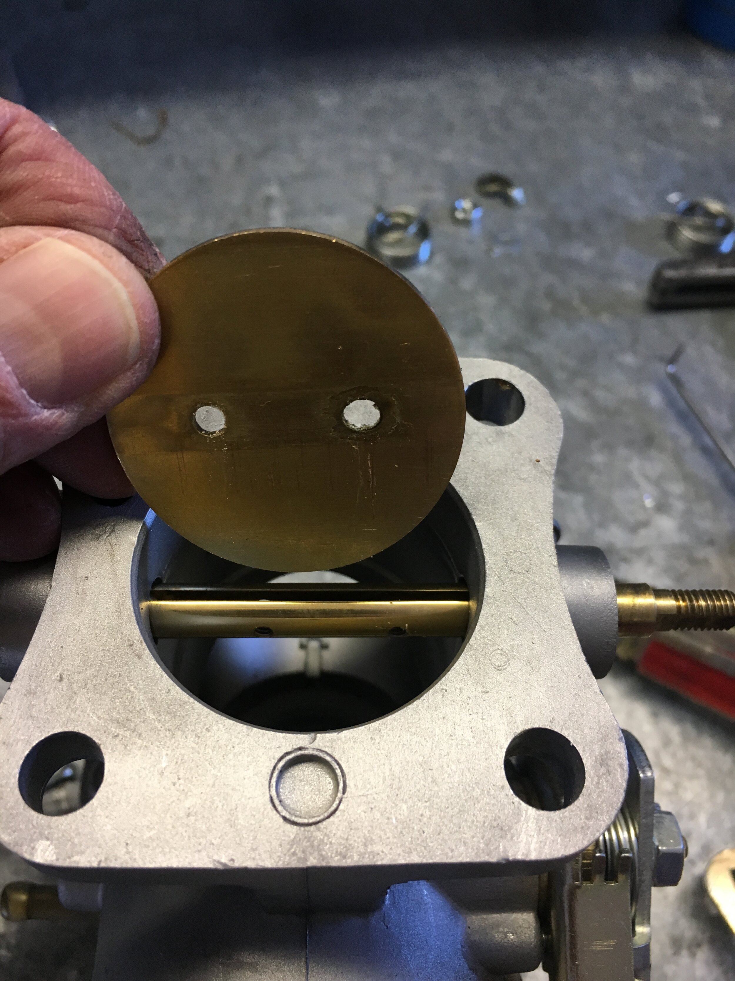
Seventh, slide out the throttle shaft and set aside with the butterfly:

Eighth, using a pick or small flat-blade screwdriver, gently remove each seal, noting how the lip is oriented outward and inspecting it for wear or damage:
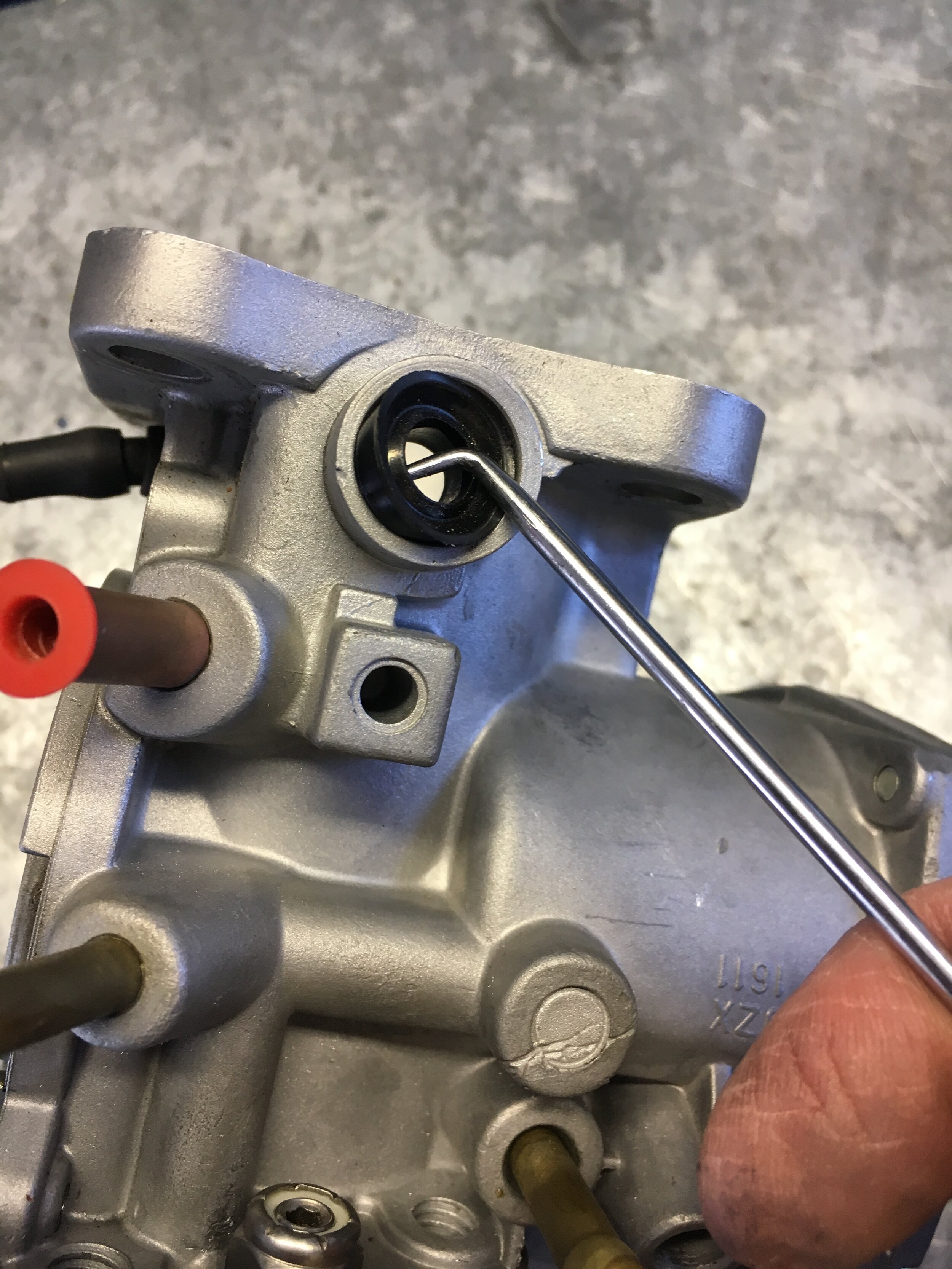
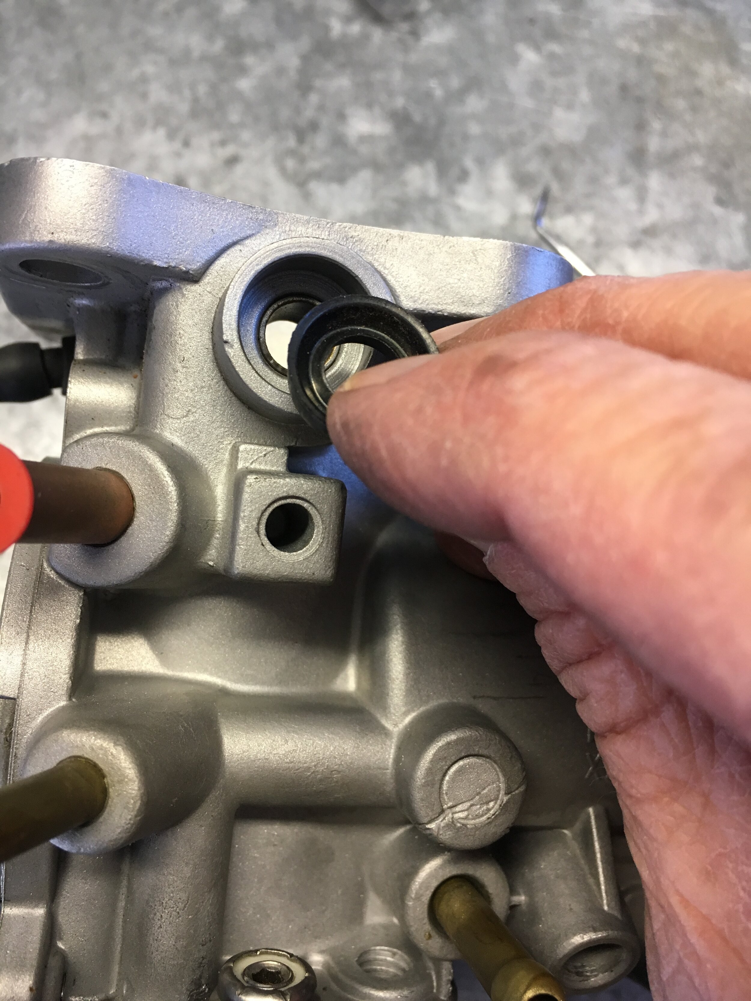
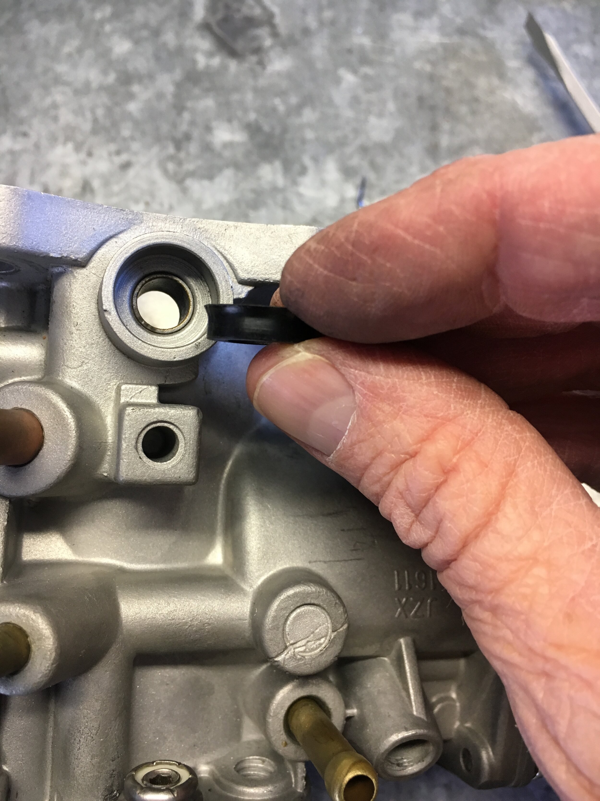
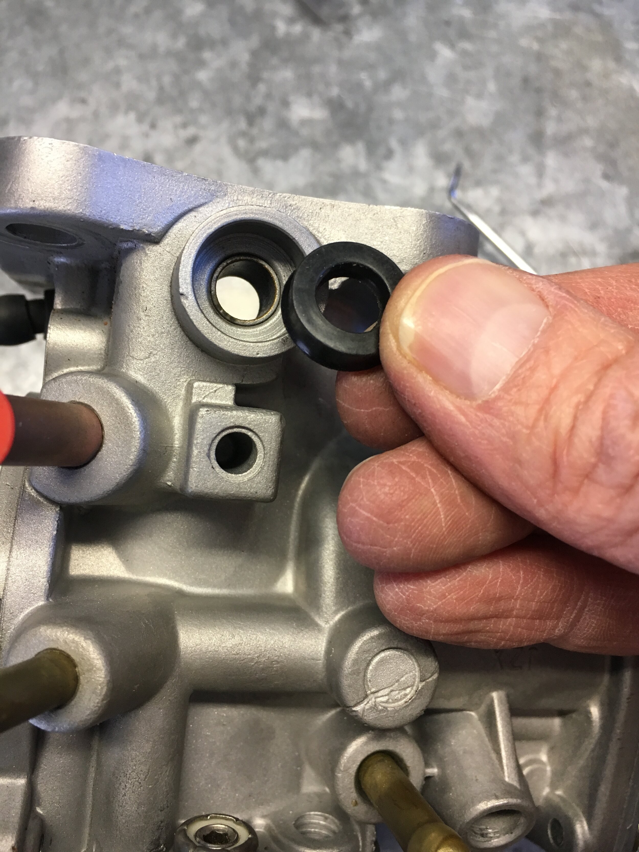
Ninth, slip the seal in at an angle with your finger, then gently use a pick or small flat-blade screwdriver to coax the sealing lip into the well. We used a circular motion with good results. Finish up by pressing the seal home with your finger:
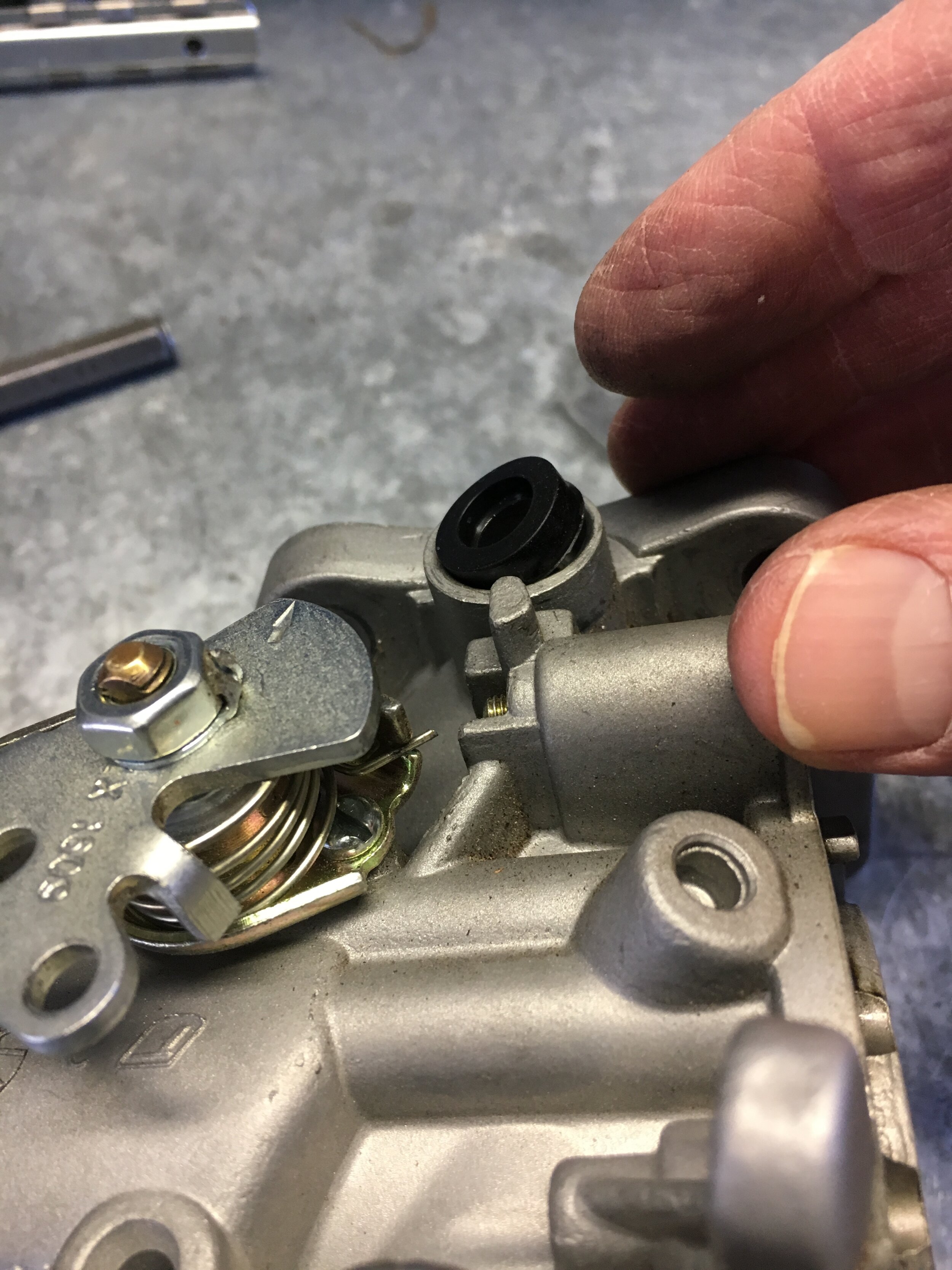
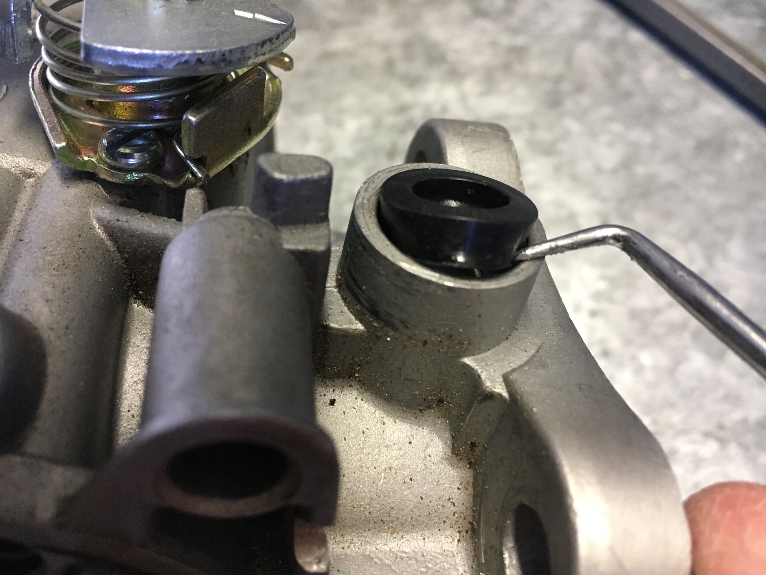
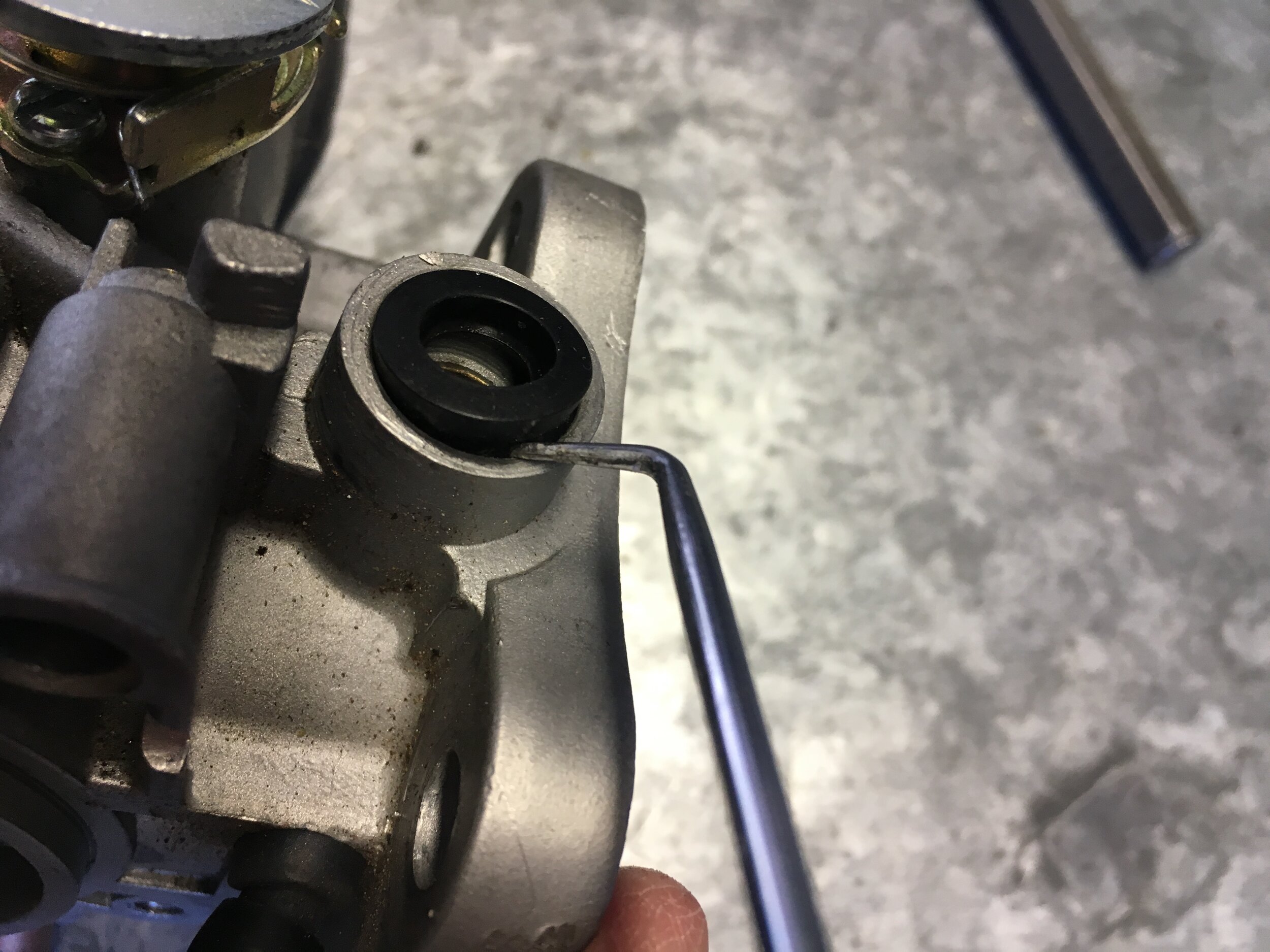
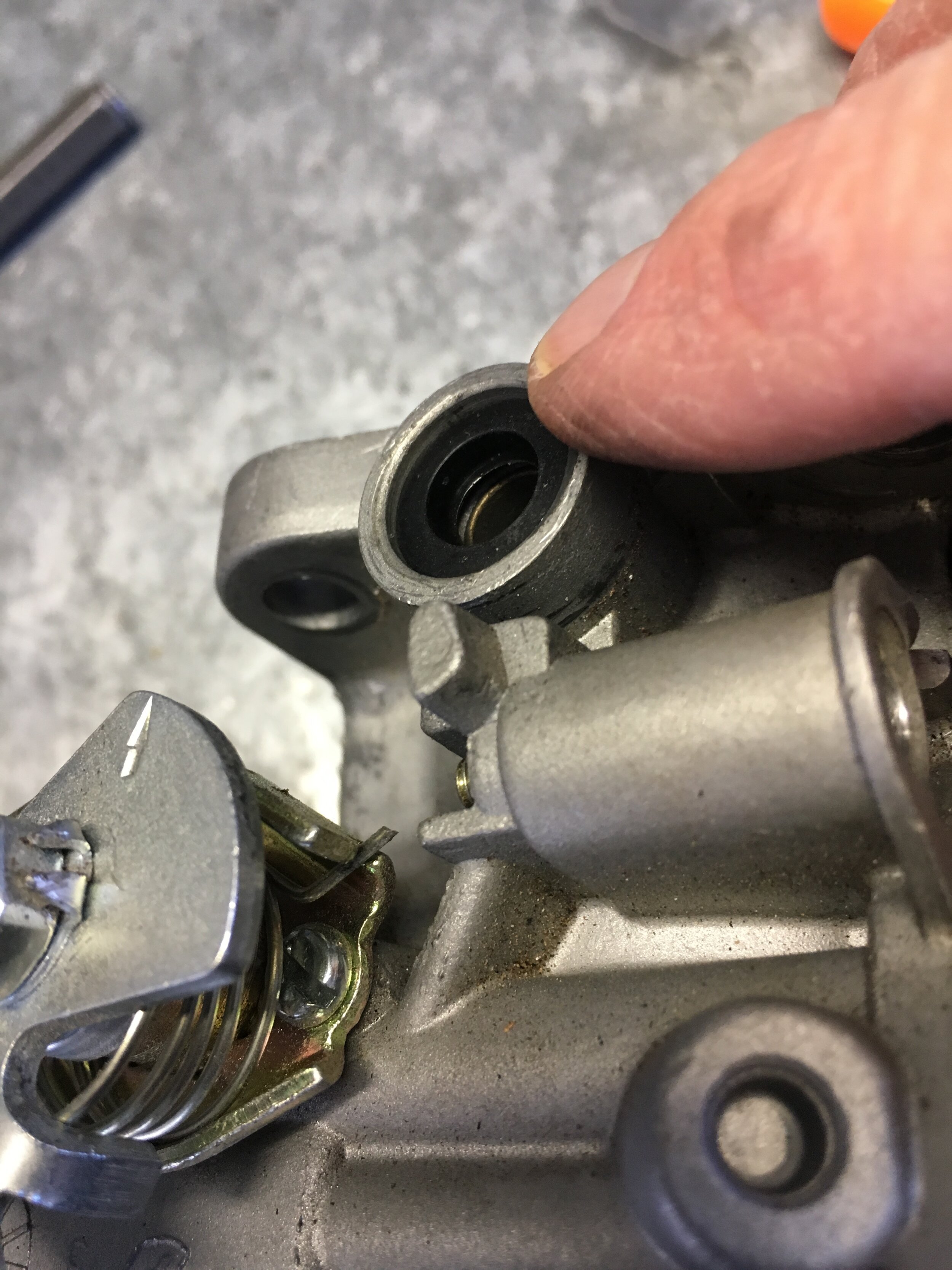
Tenth, gently slide the throttle shaft back into place, taking care to keep it aligned, so as not to tear the seals with the threads:
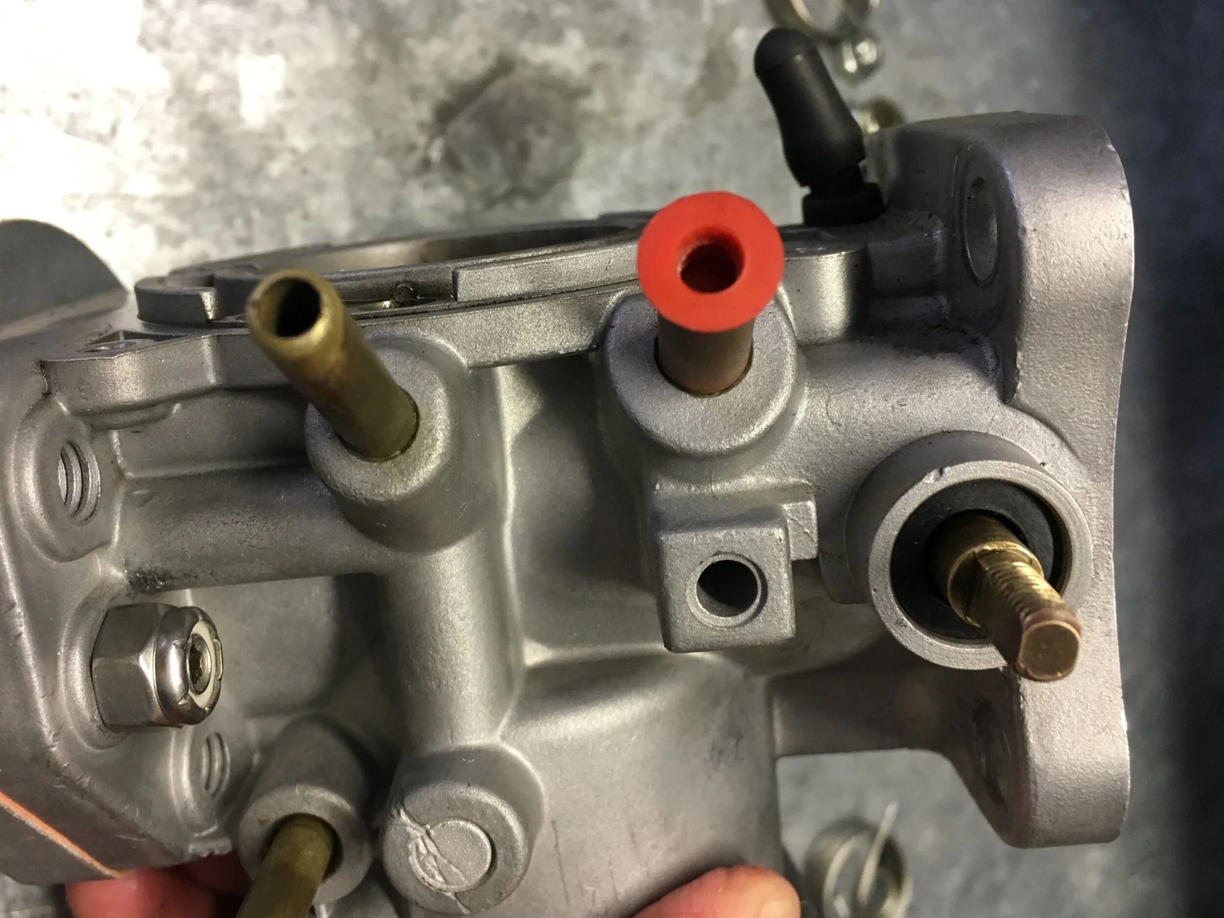
Reassemble in reverse order. Here are some tips, as there is one possible error and replacing the springs is a little tricky:
First, insert the shaft so that the countersinks for the screw heads are toward the manifold side of the carb—but note that it is possible to insert the throttle butterfly incorrectly, so that the shaft pivots the wrong direction.
Make sure you can see the distributor vacuum port when the butterfly is closed, and that the bottom swings inward, or toward the manifold:
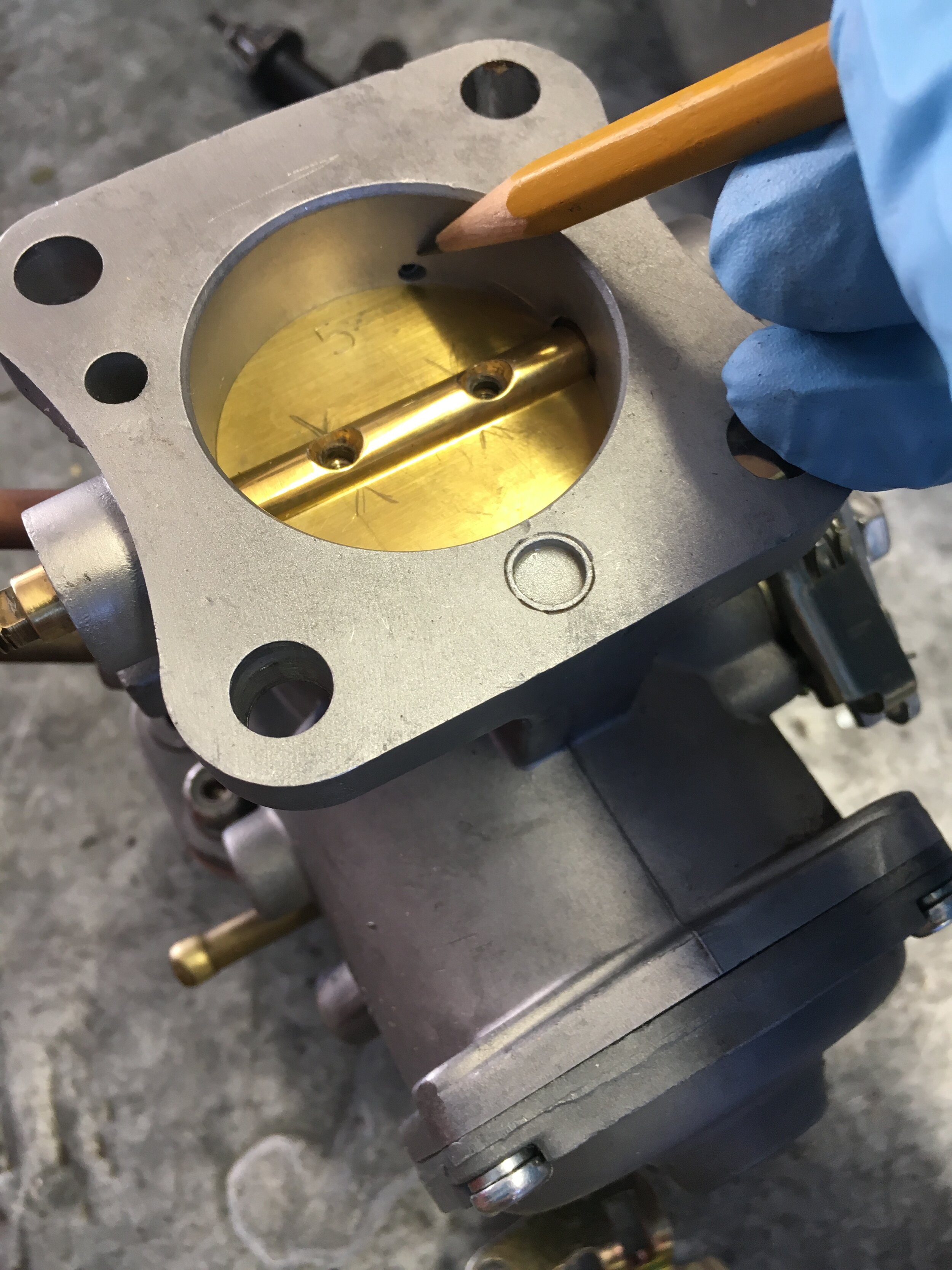
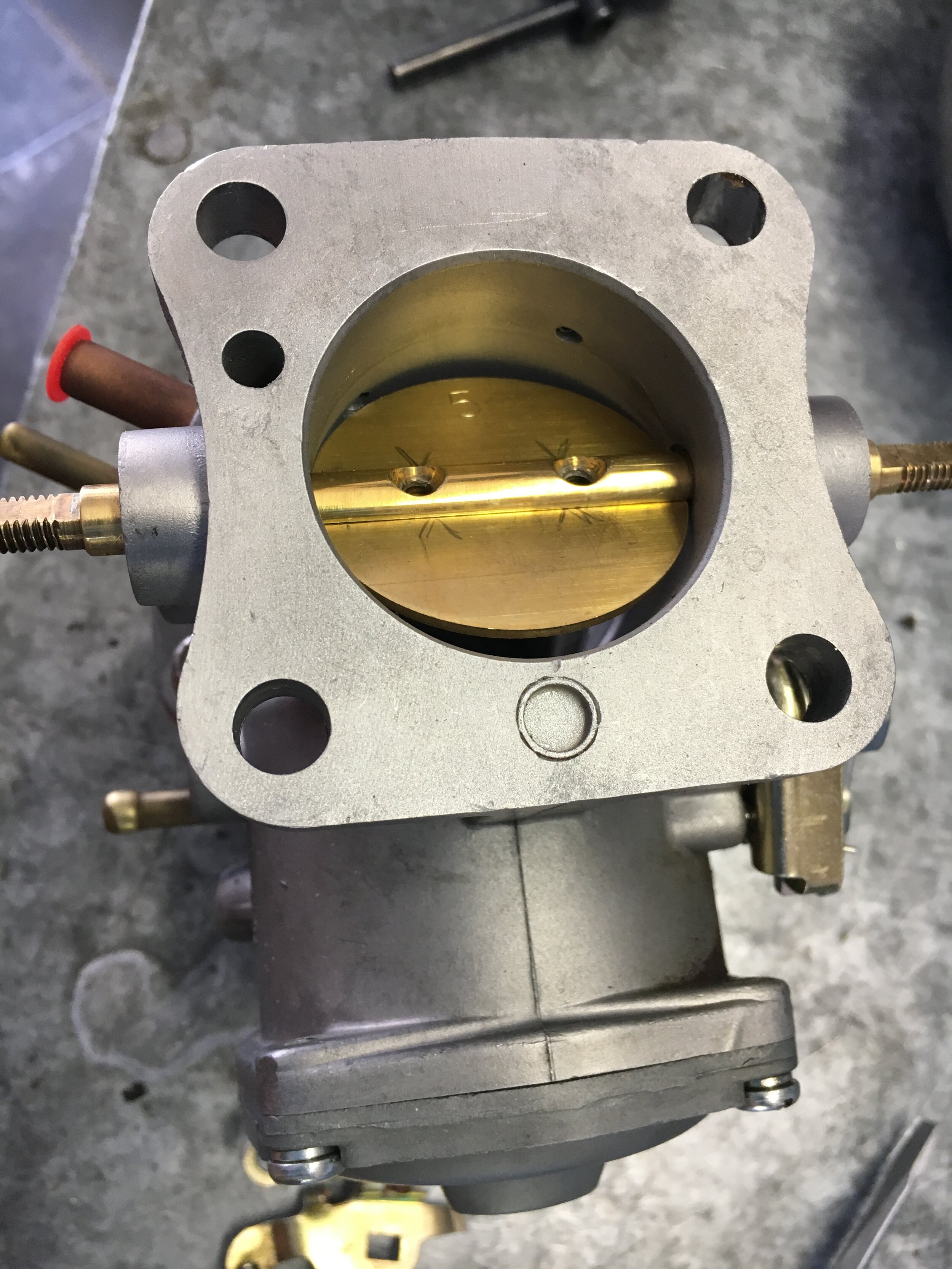
Second, loosely insert the throttle butterfly screws, and gently move the shaft back and forth to center the butterfly as you gradually tighten the screws:
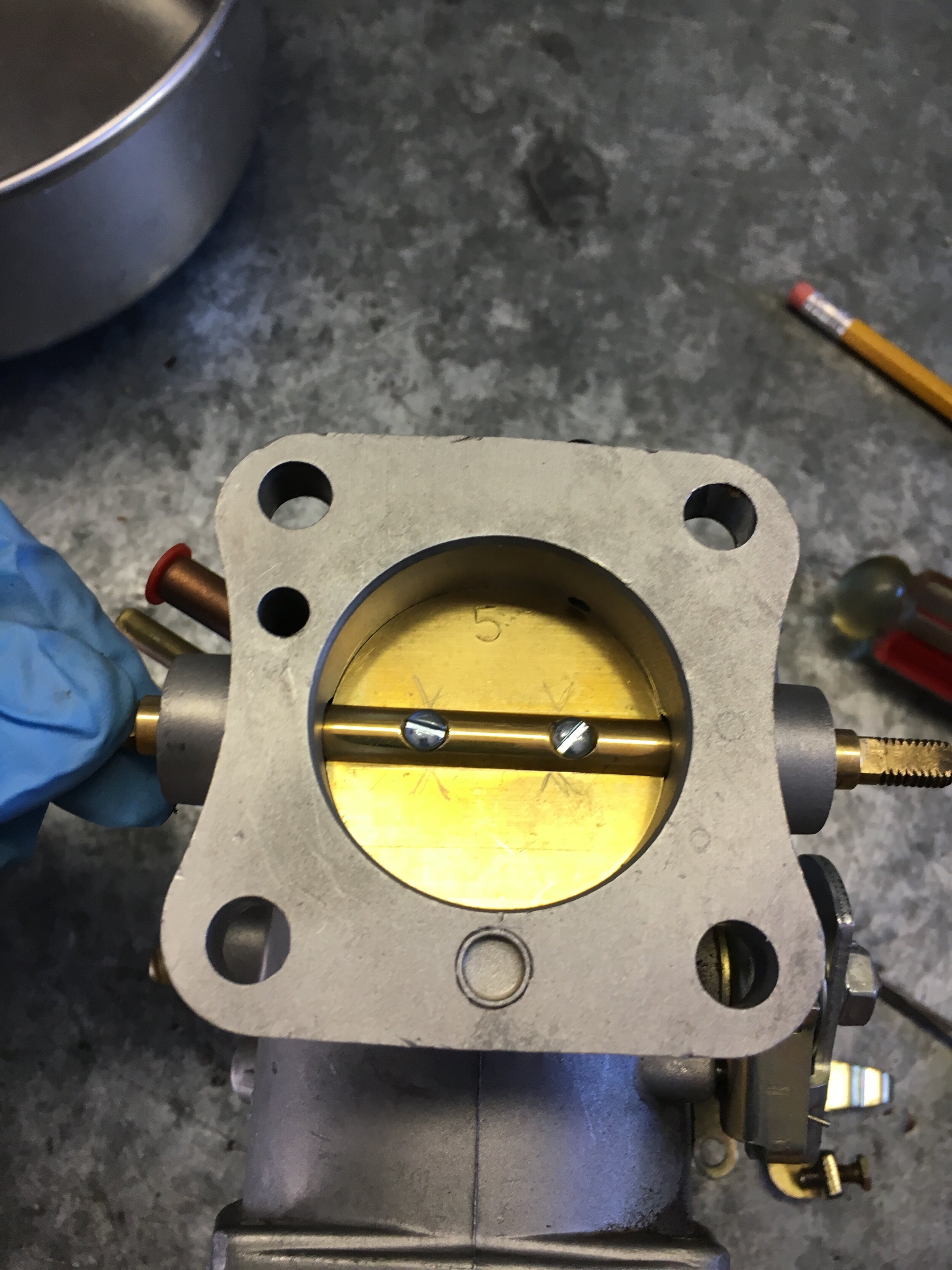
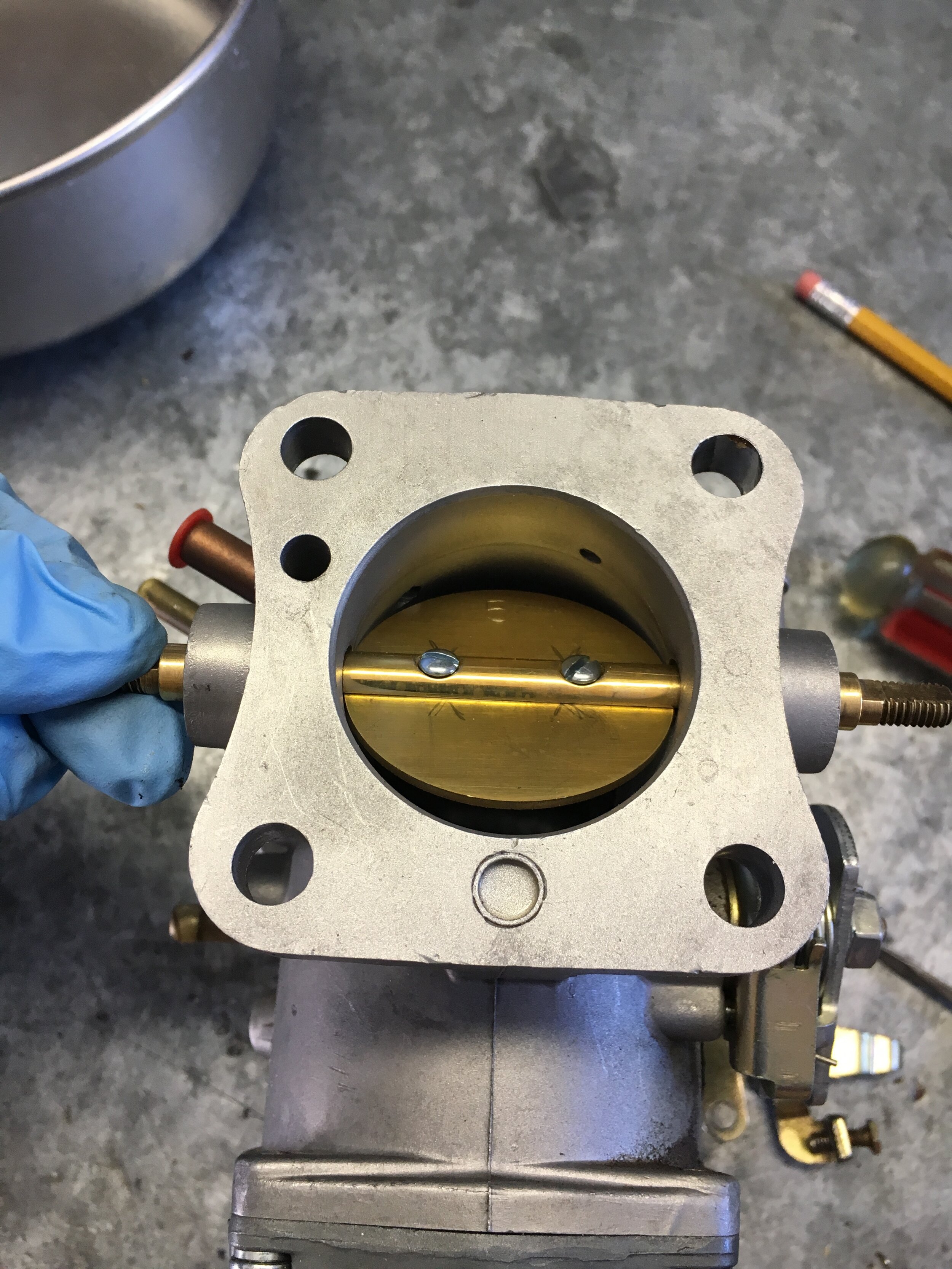
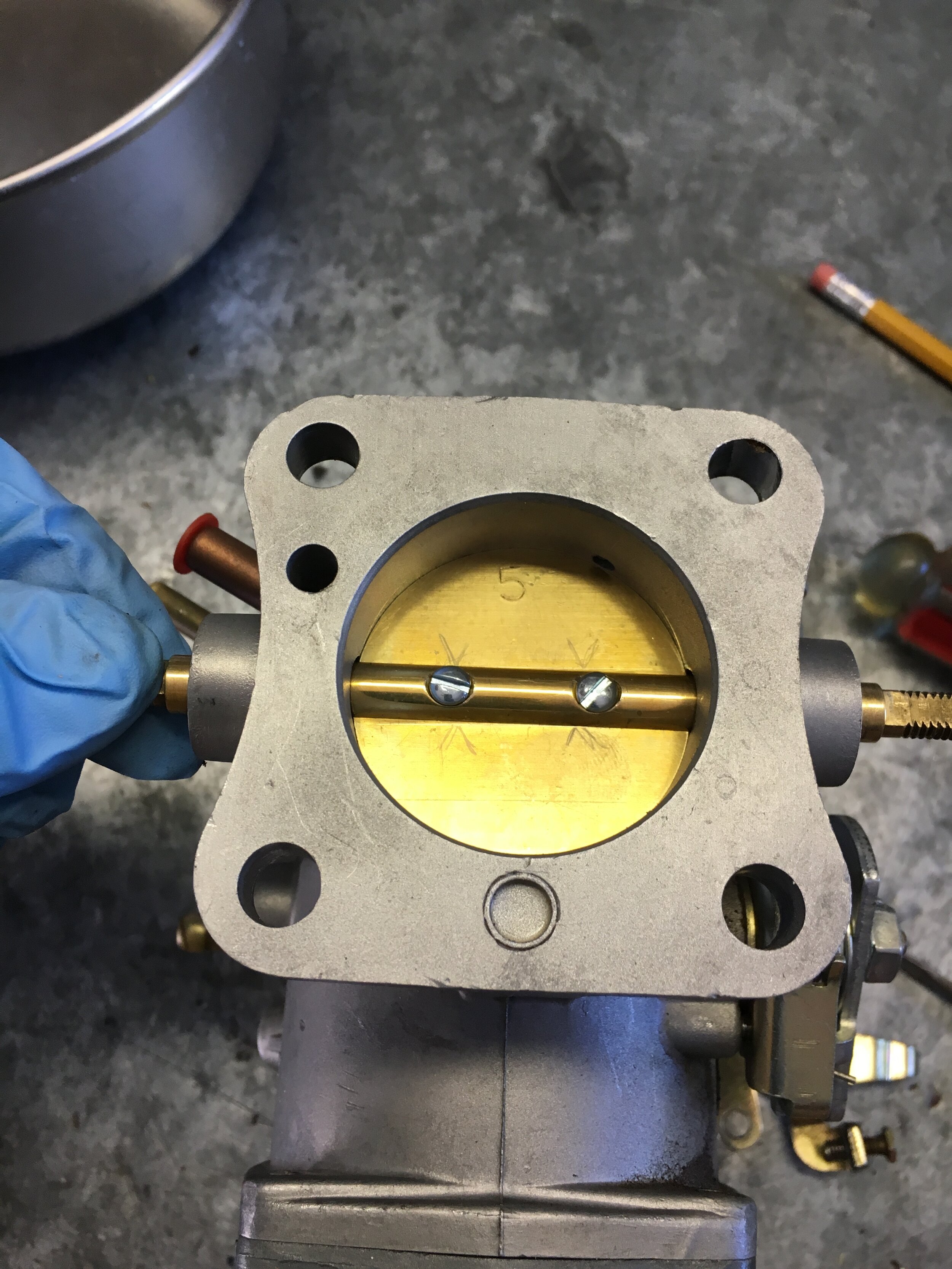
Third, firmly seat the screws—you will feel a light but positive stop—and then flip the butterfly 180 degrees to gently splay the slotted ends of the screws. Using a small flat-blade screwdriver, splay the screws sufficiently to prevent loosening, but be careful not to break them off:
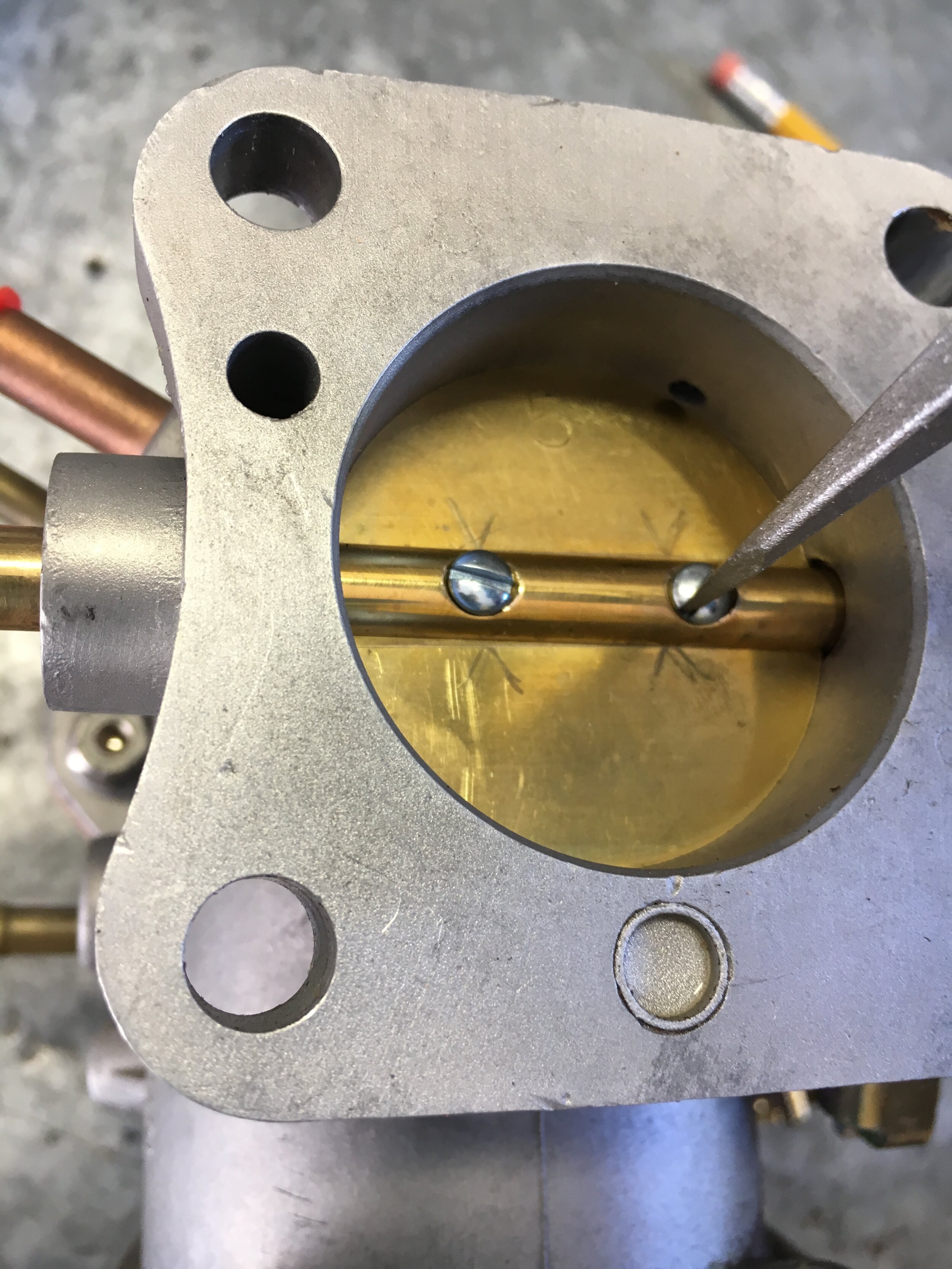
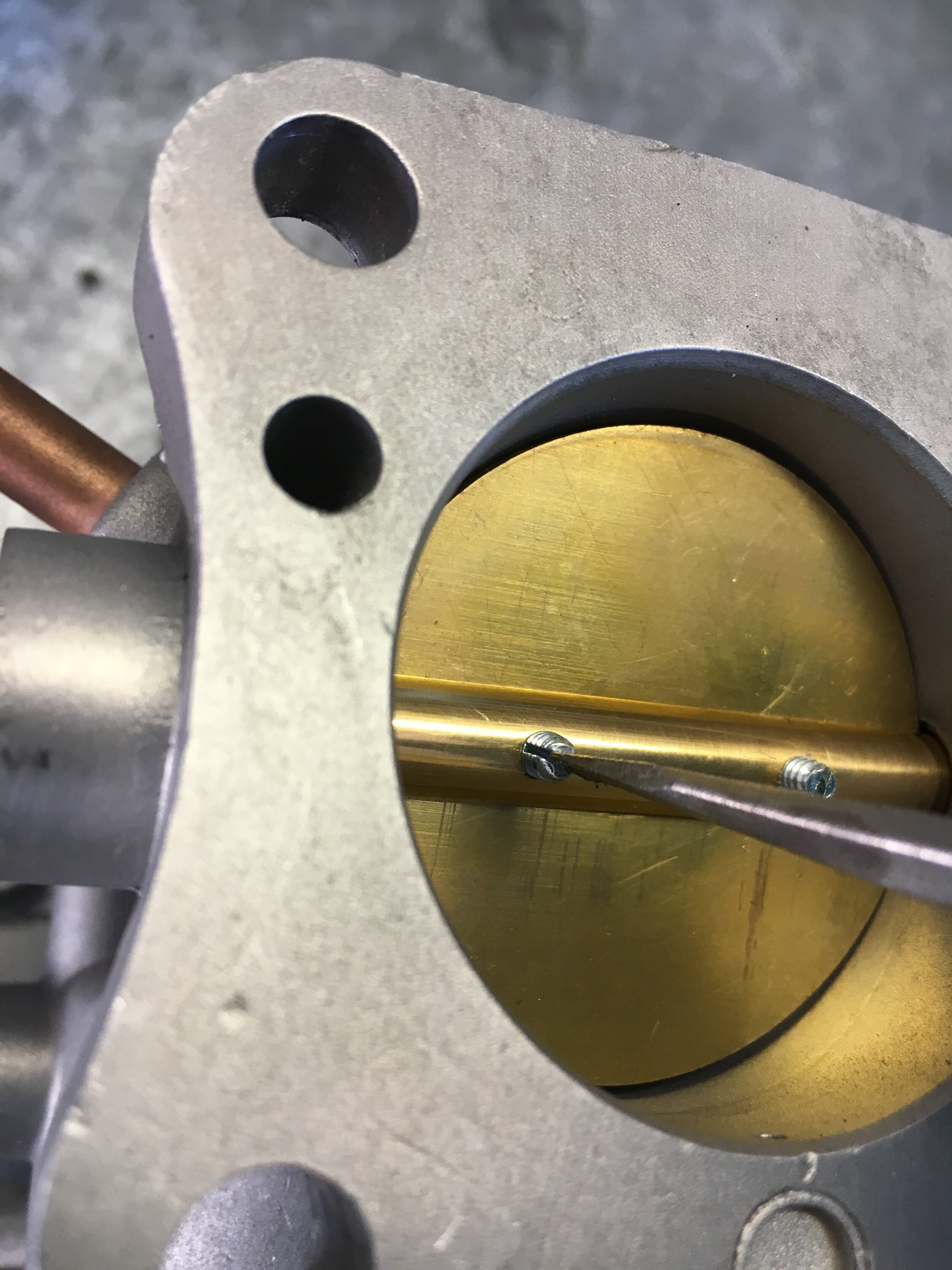
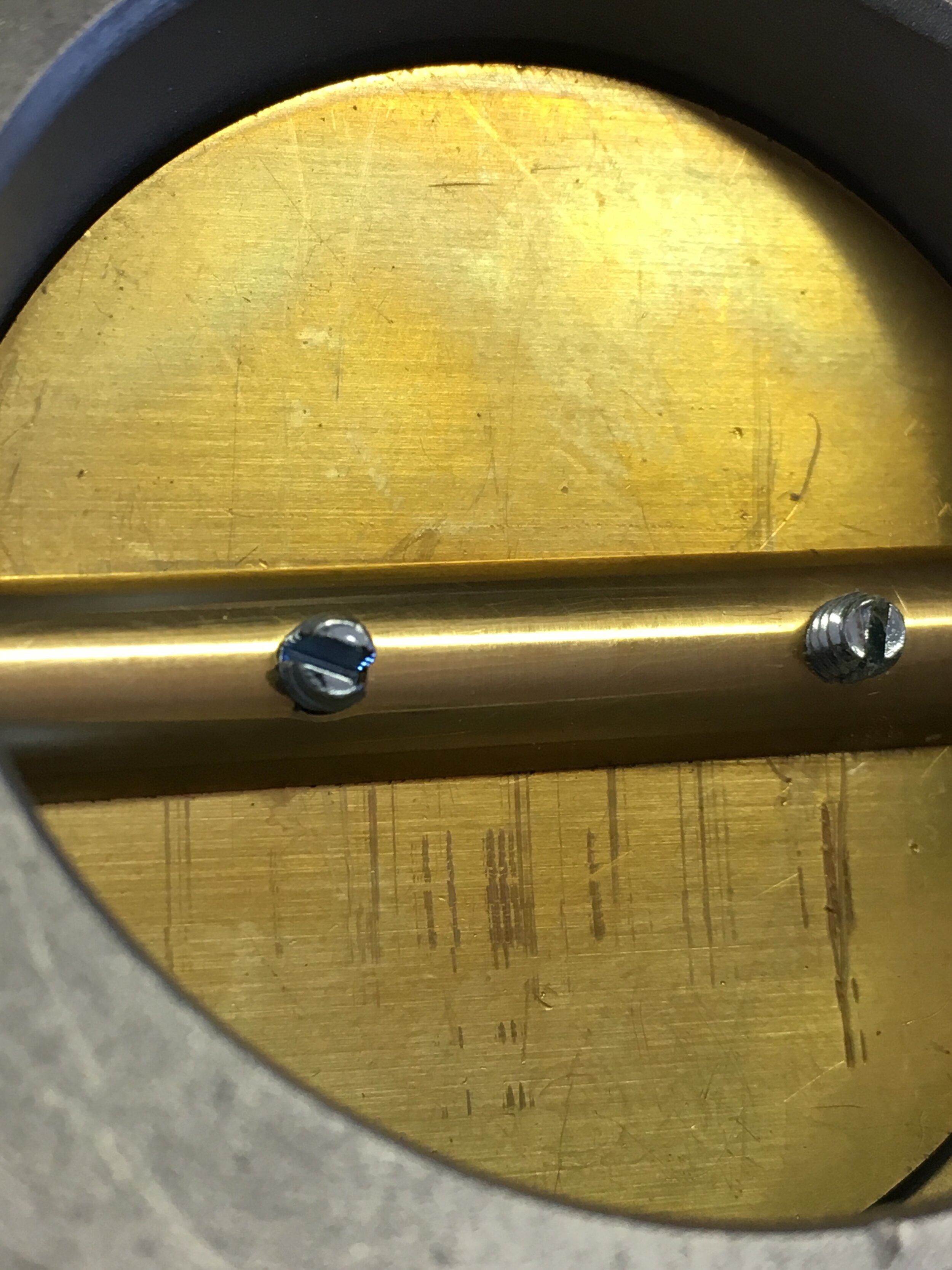
Fourth, replace the spring on the throttle-lever side of the carburetor, and using your fingers or needle-nosed pliers (you will need two pairs), wind the spring 180 degrees to rest on the stop like this:
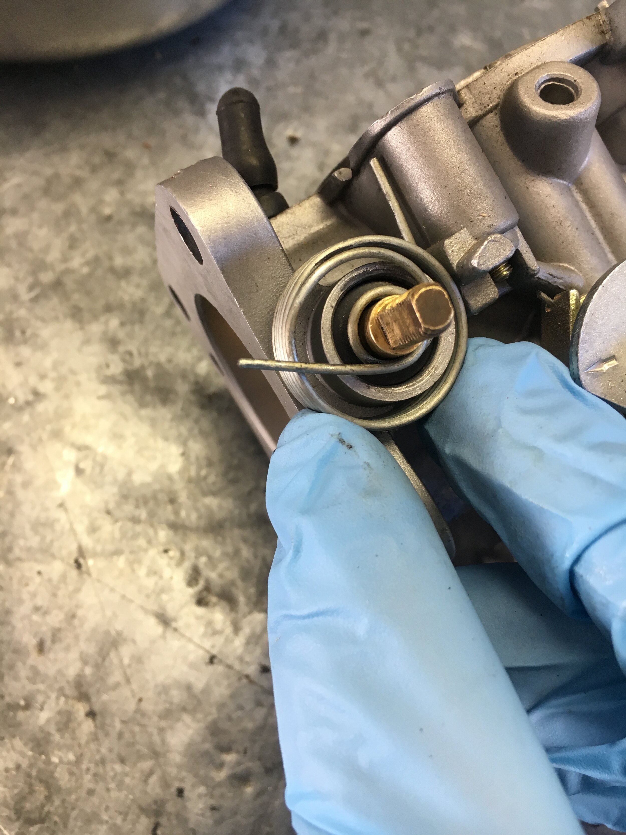
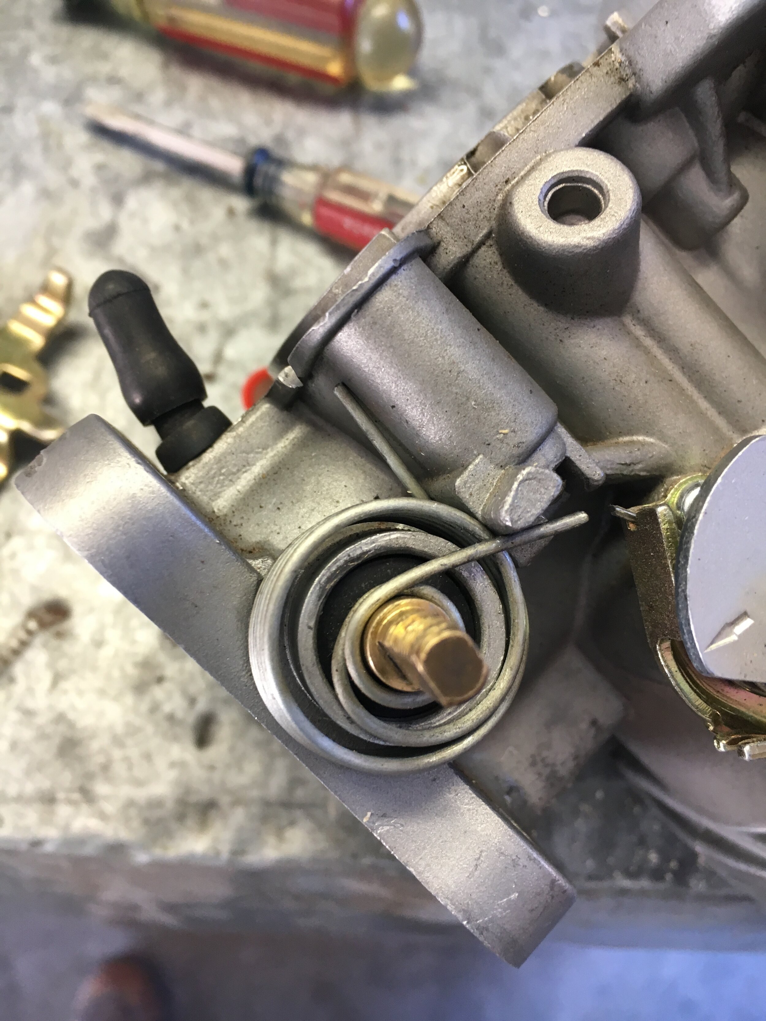
Fifth, position the carburetor against something to prevent it from pivoting, squeeze it between your knees, or have a helper hold it, grab two pairs of needle-nosed pliers, and make sure you have the throttle lever, locking tab washer, nut and 1/2” deep-well socket within reach.
When you are ready, wind the spring another 180 degrees with one pair of pliers, grab the spring from below with the other pair, and slip the throttle lever into place, followed by the locking tab washer and nut—fastened tight enough to prevent the lever from flying off when you release the spring (you will tighten securely later):
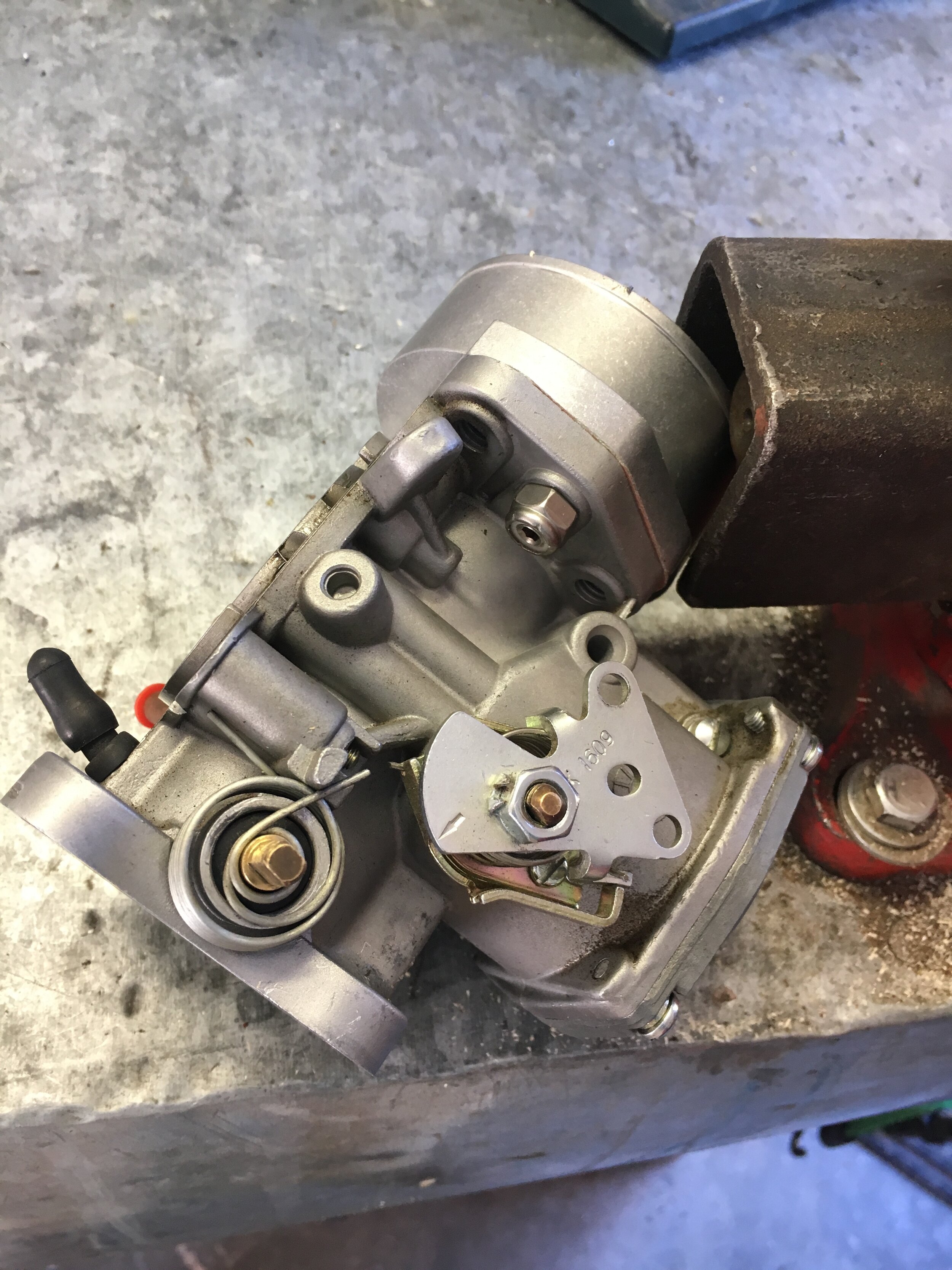
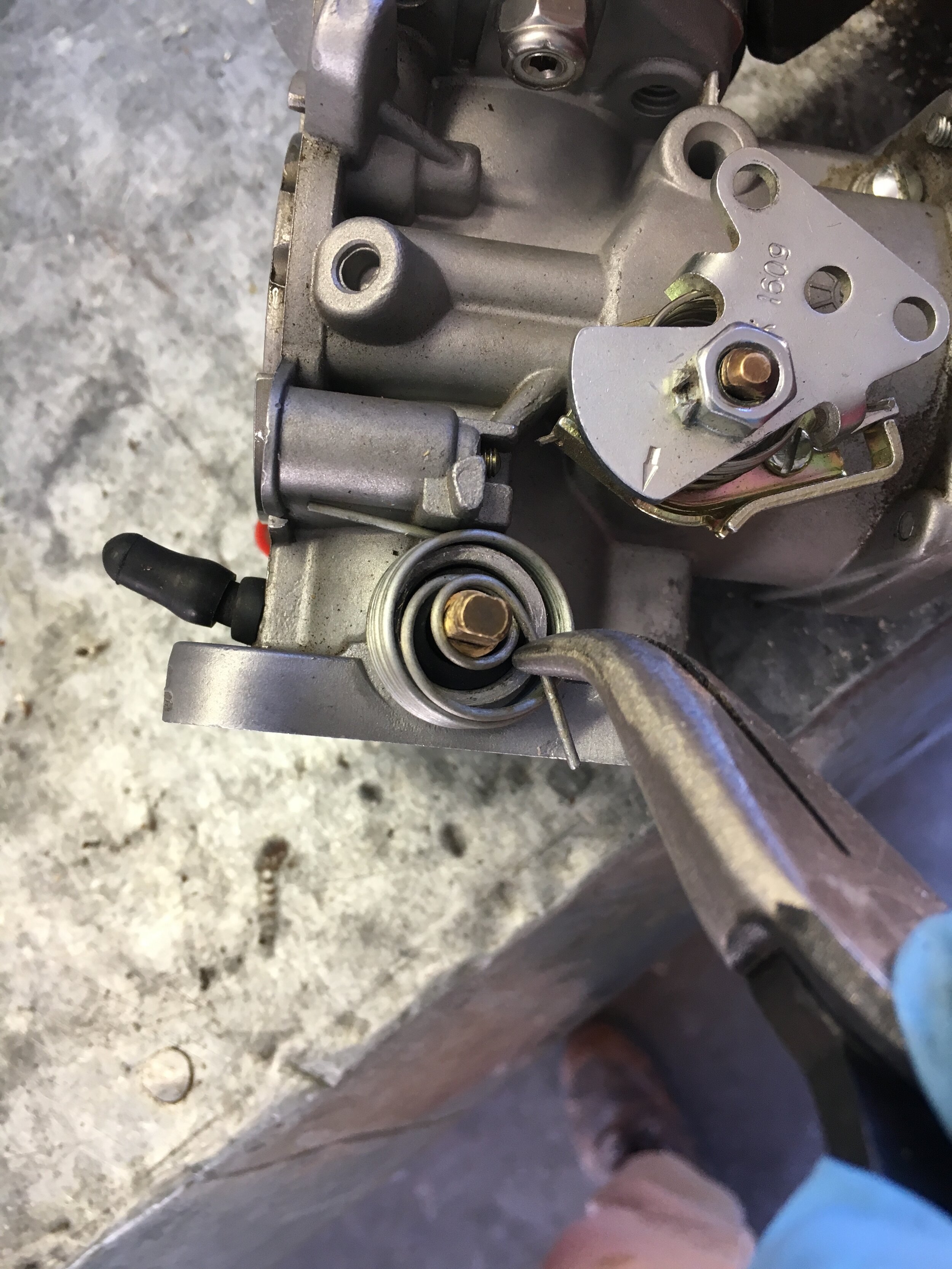
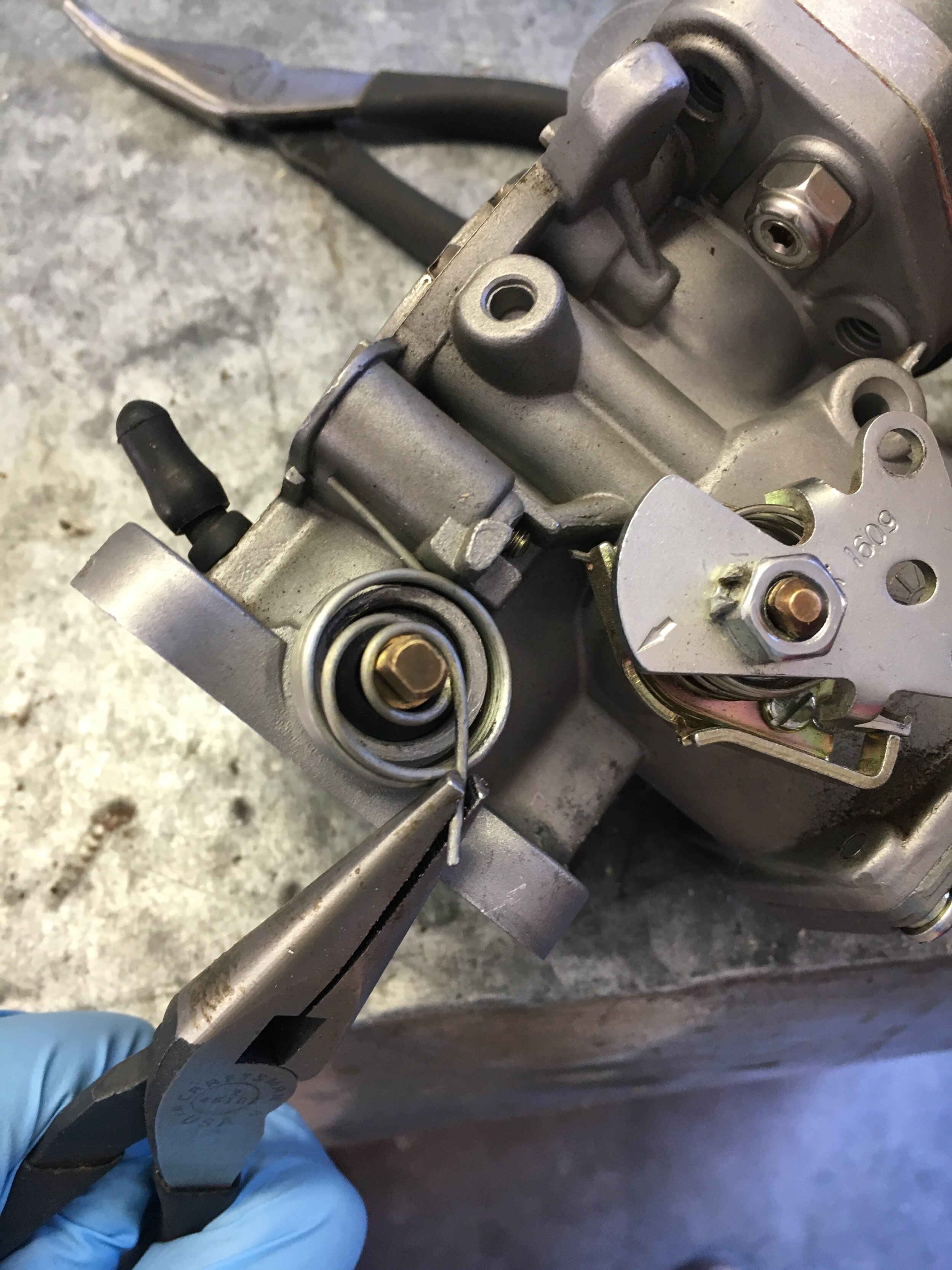
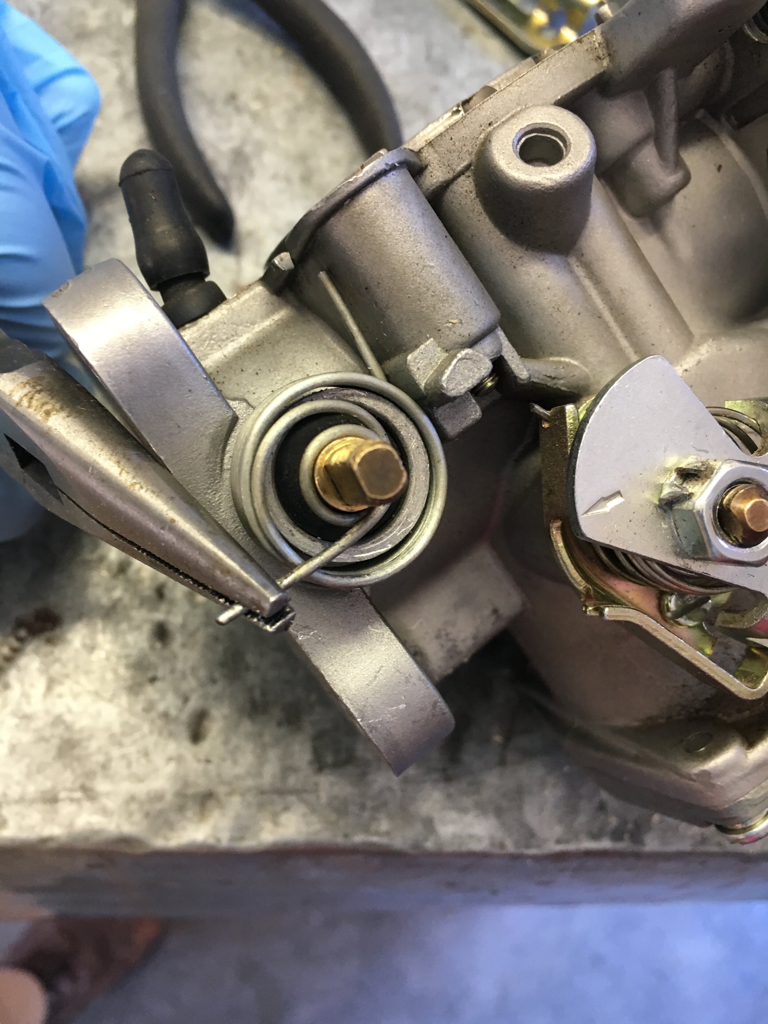
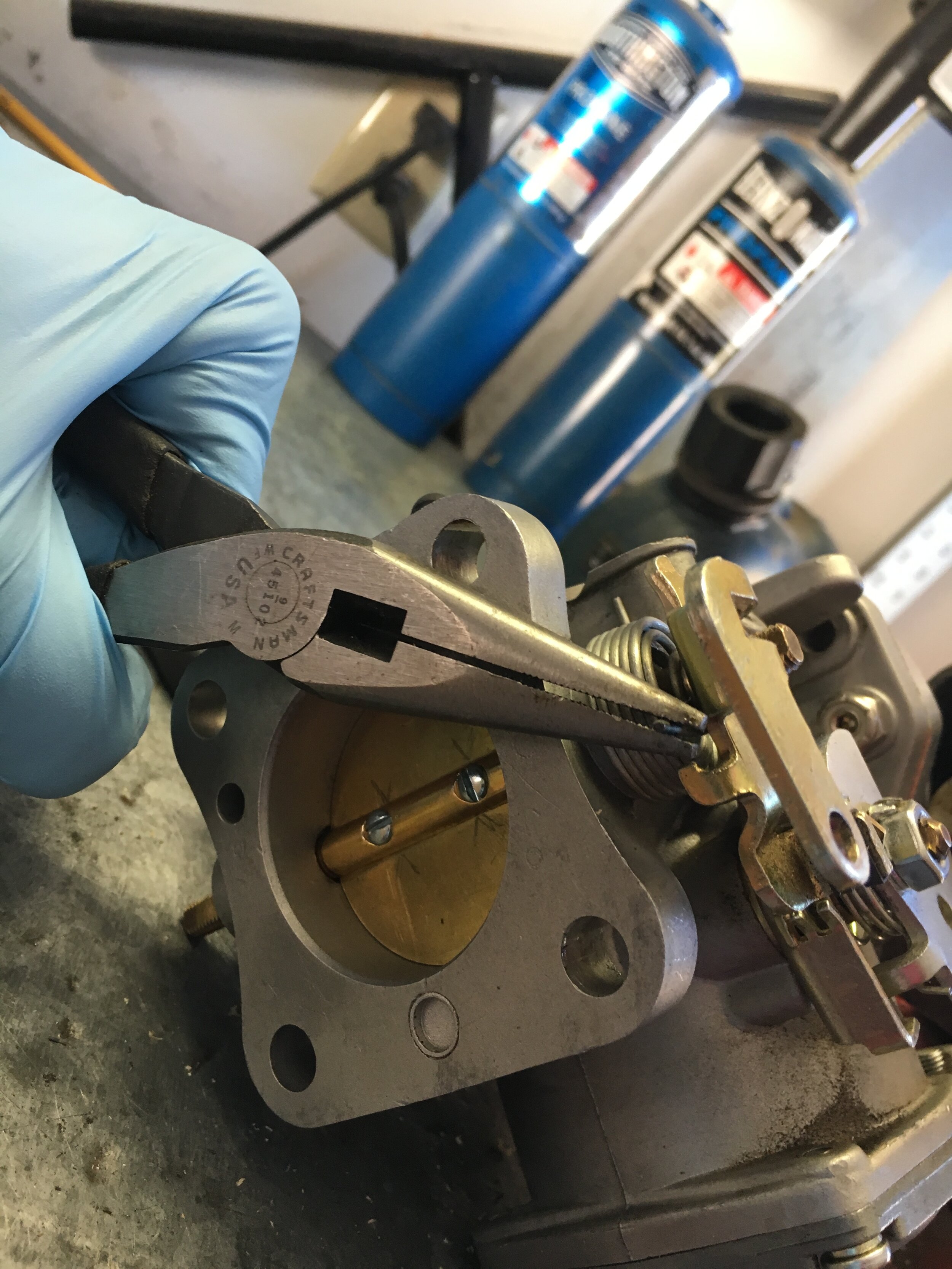
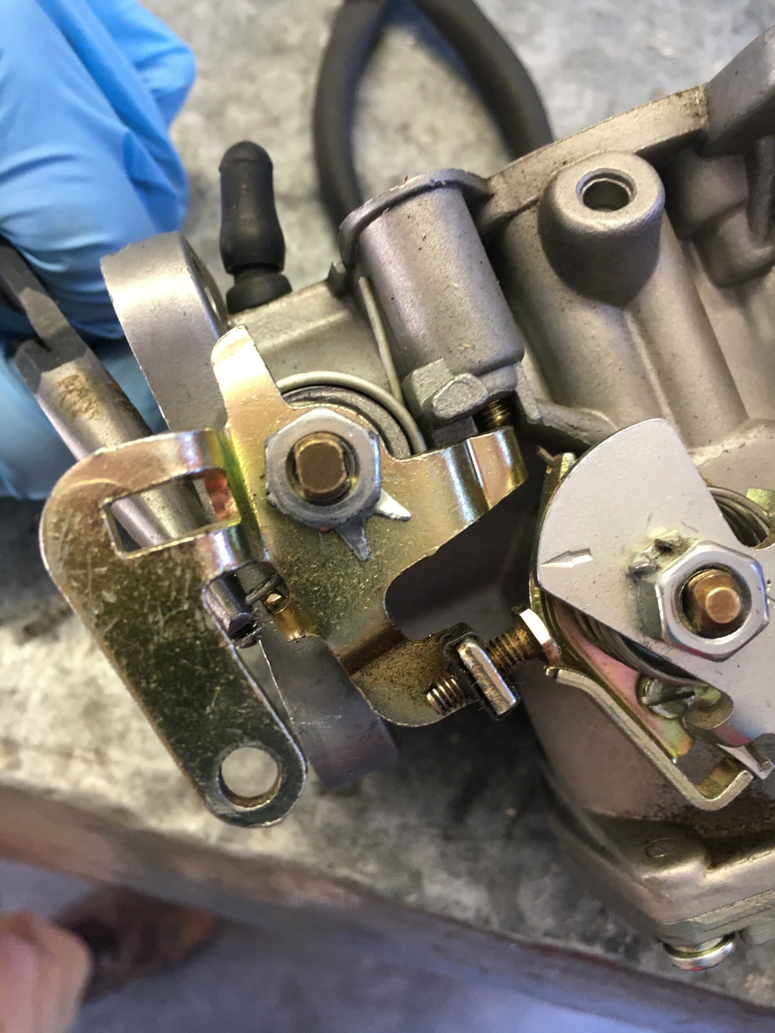
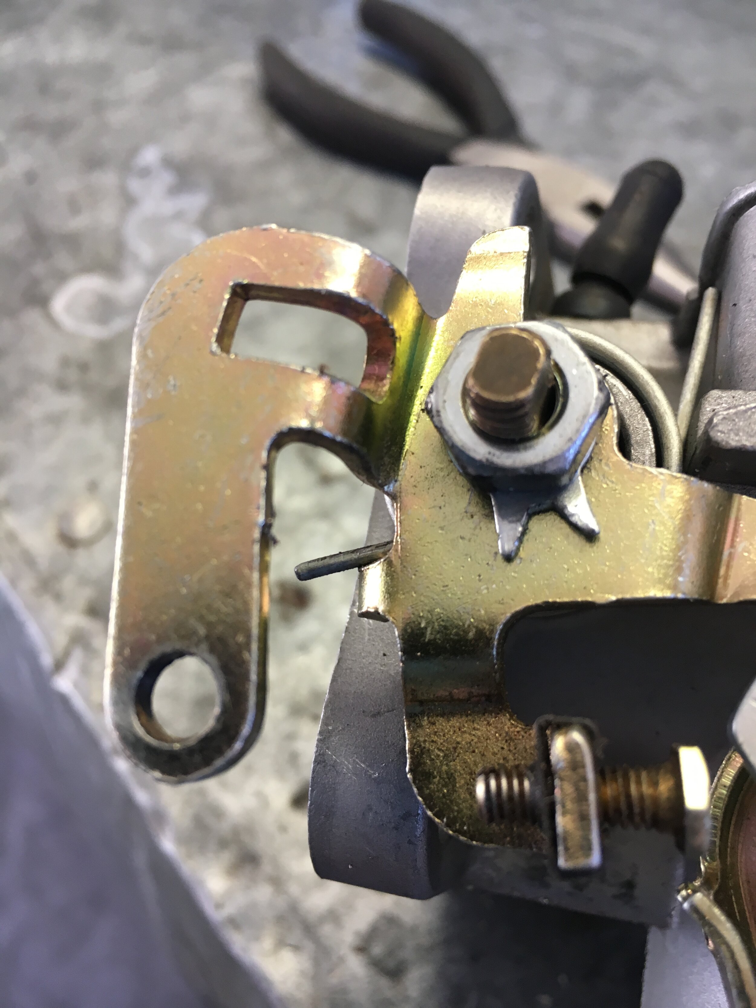
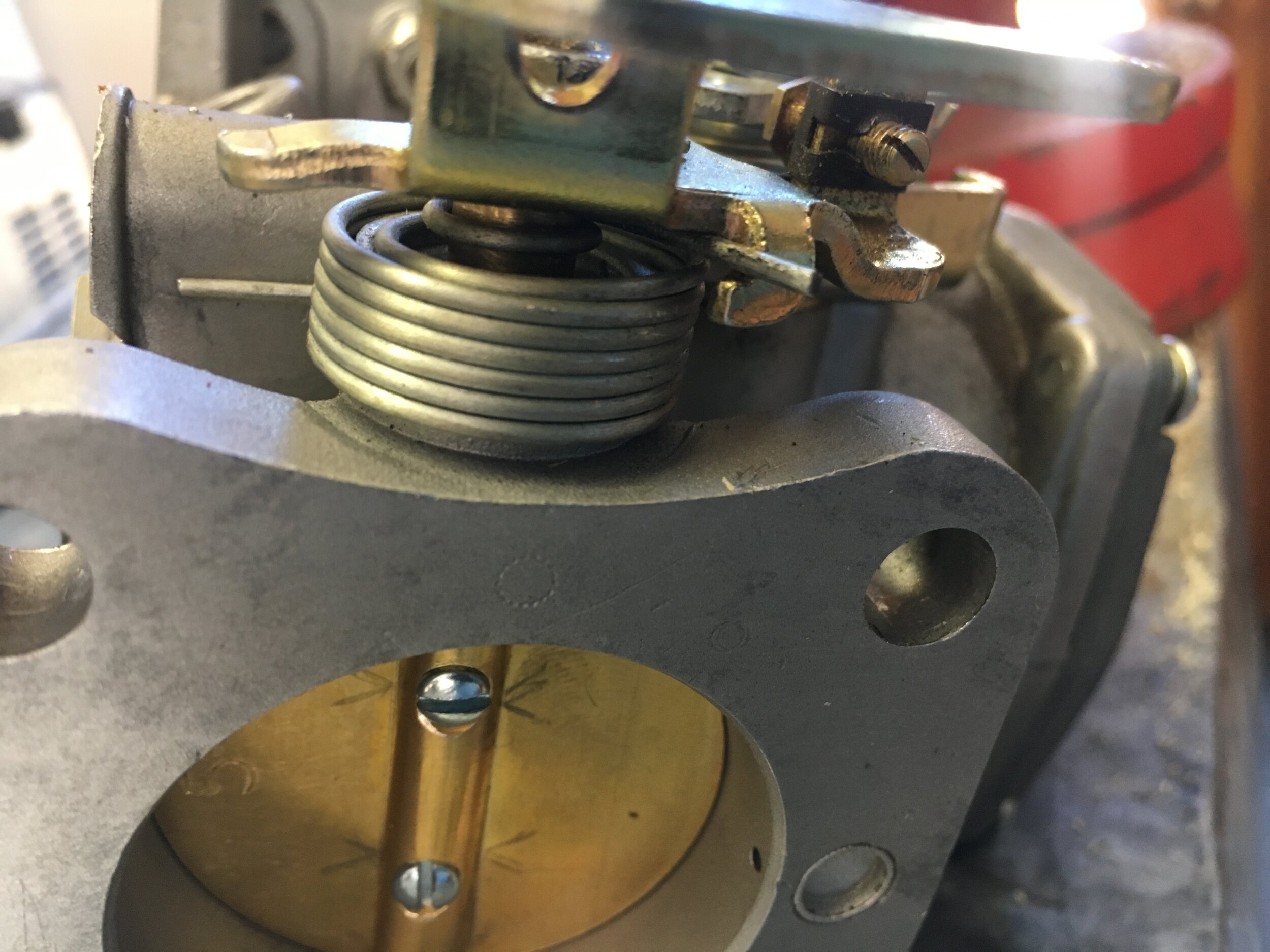
Sixth, flip the carburetor over and repeat the process on the other side, which is much simpler:
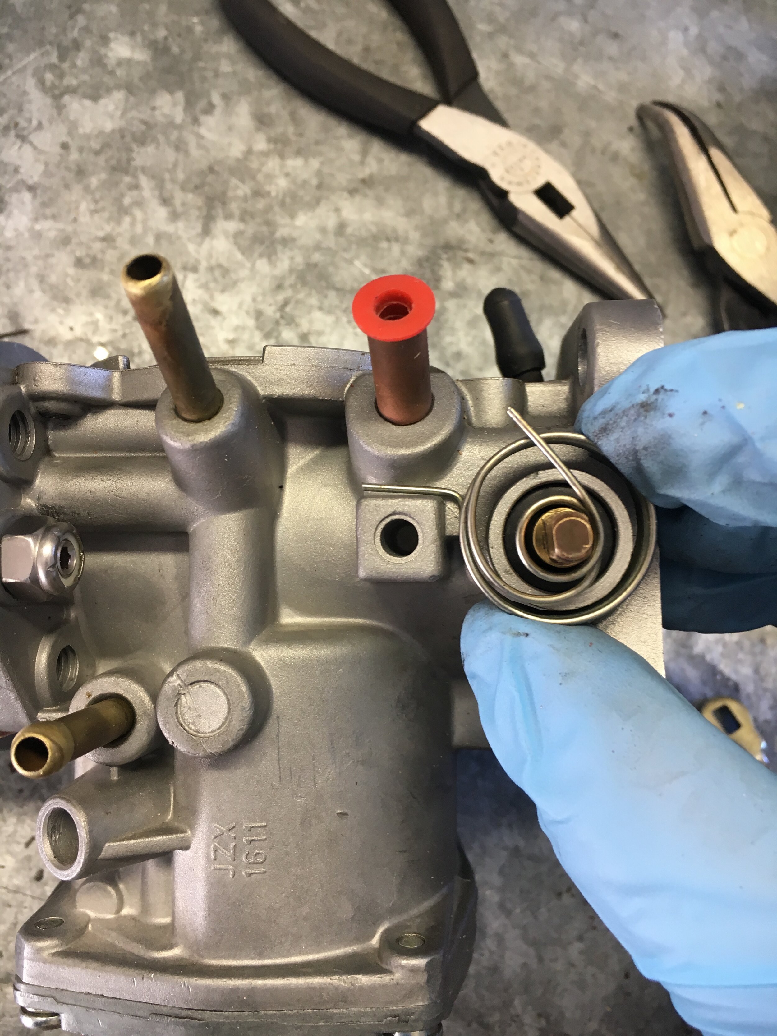
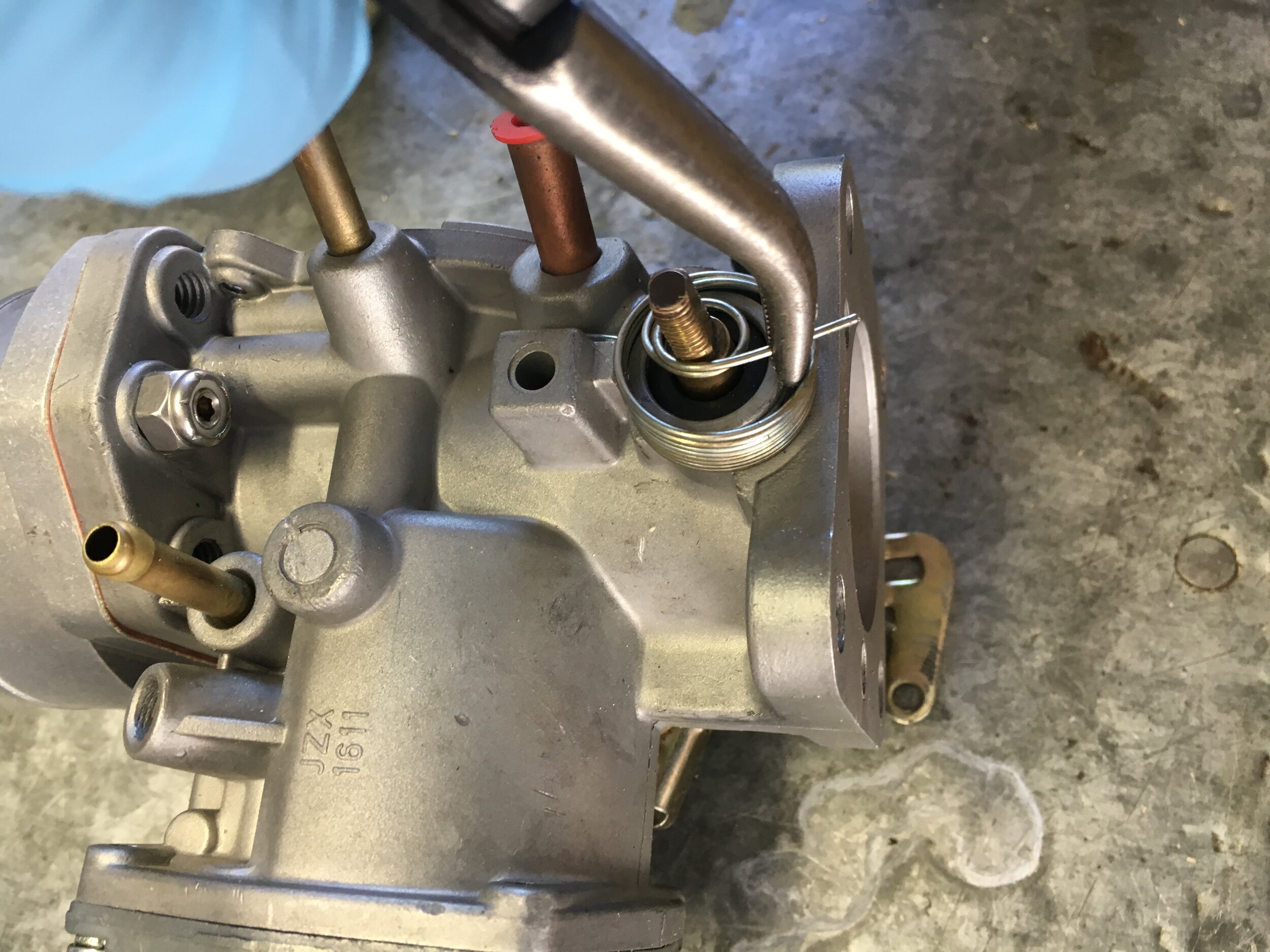
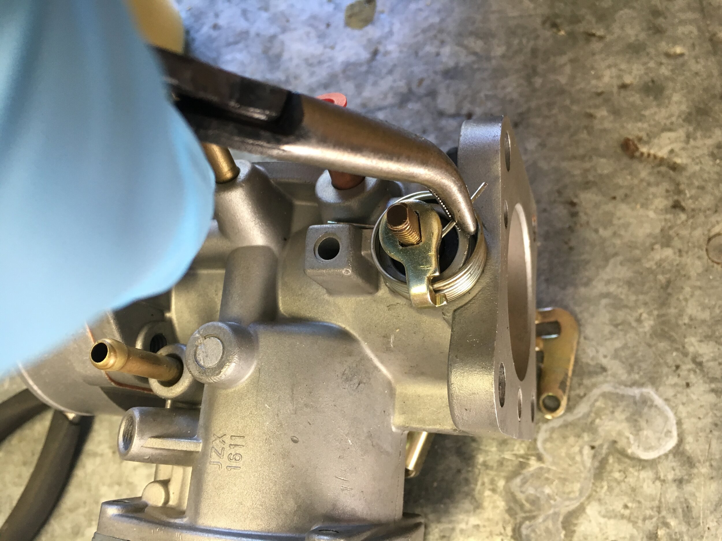
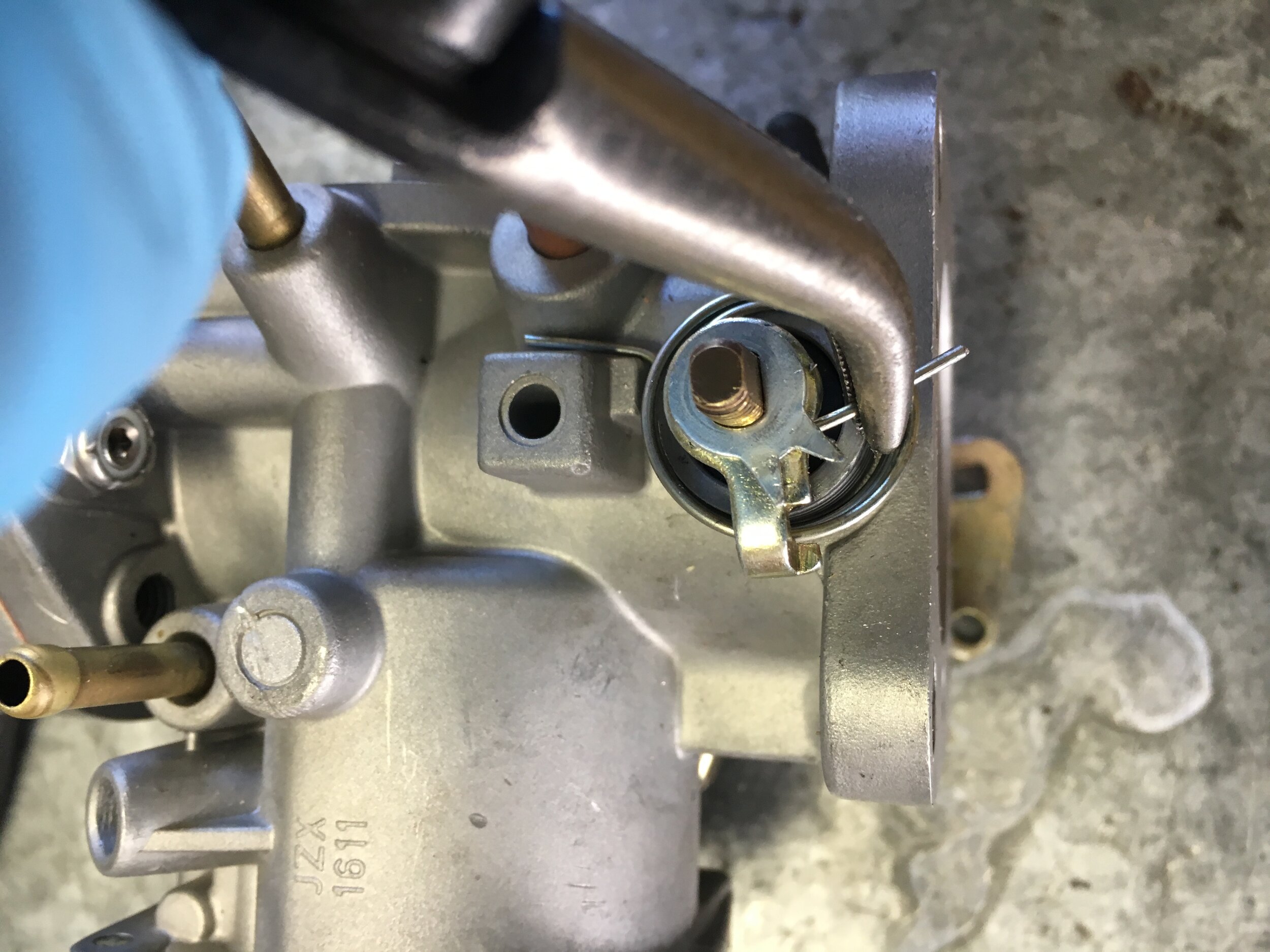
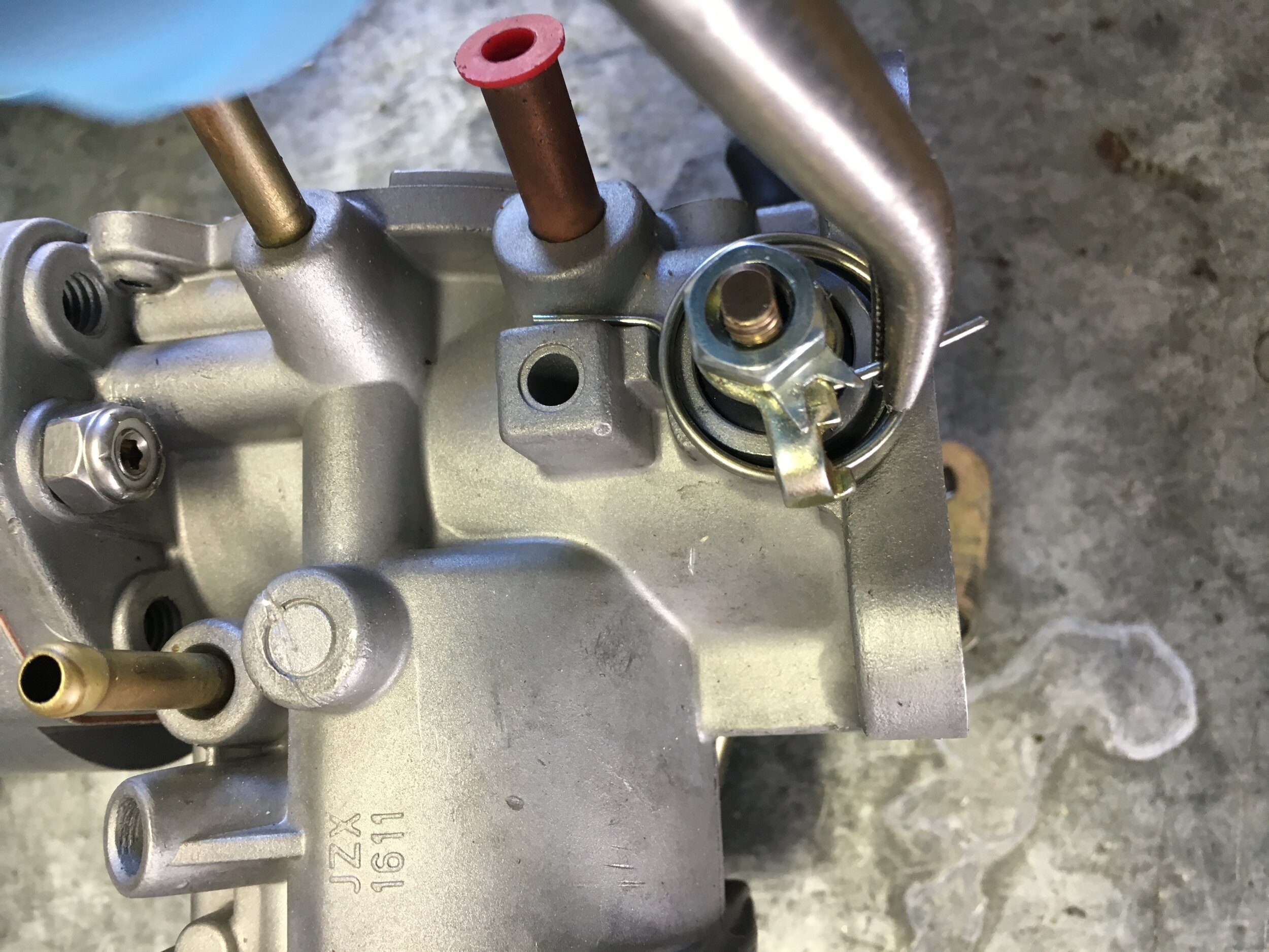
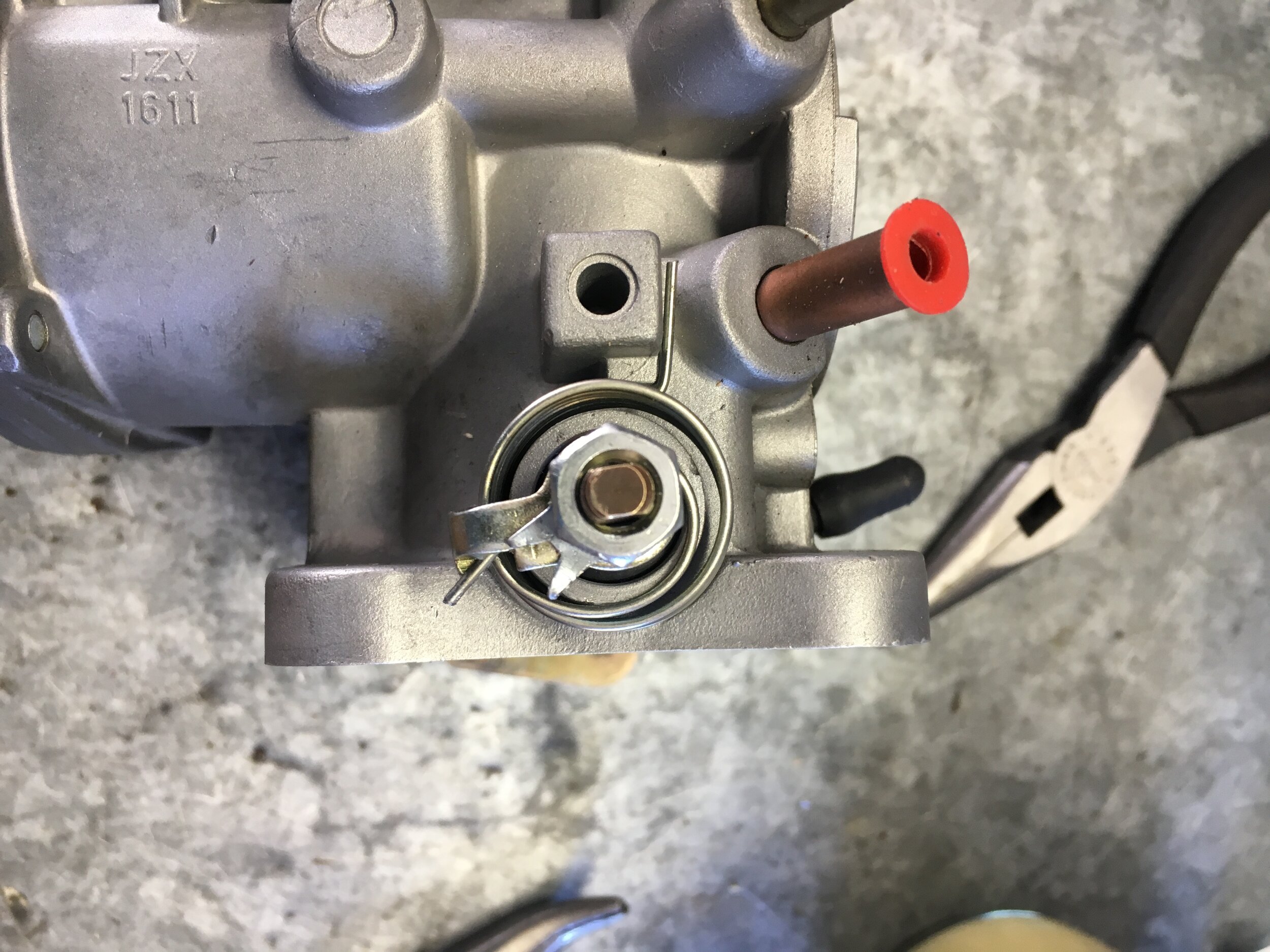
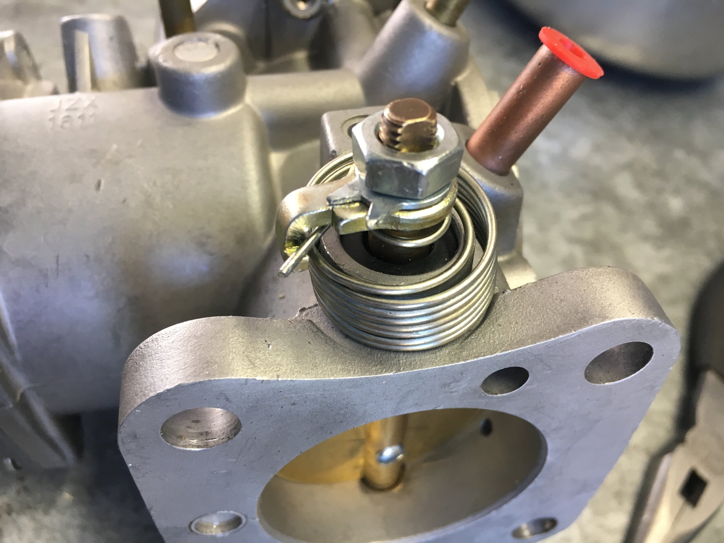
Finally, bend up the locking tab washers, using the small flat blade screwdriver and needle-nosed pliers:
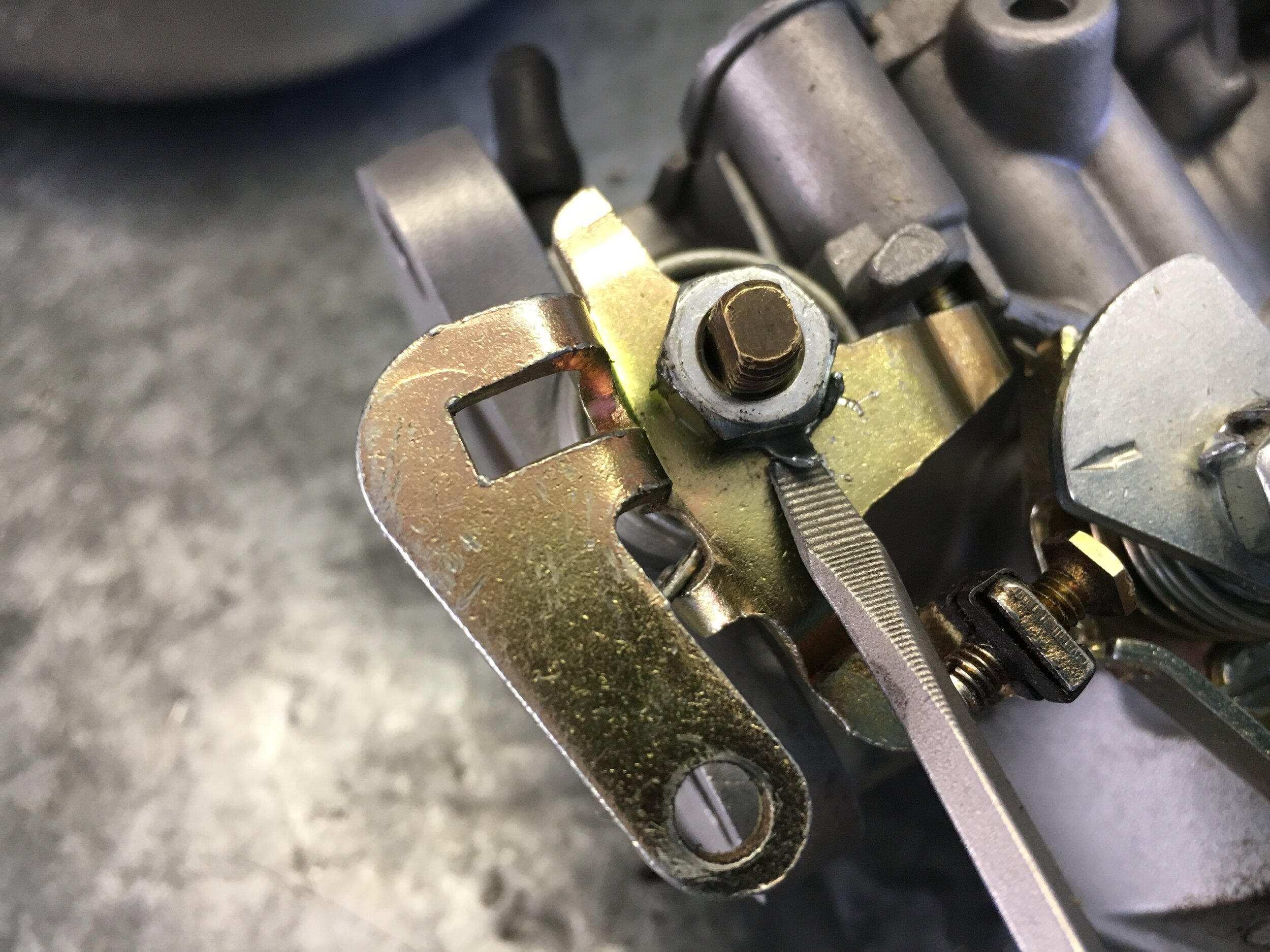
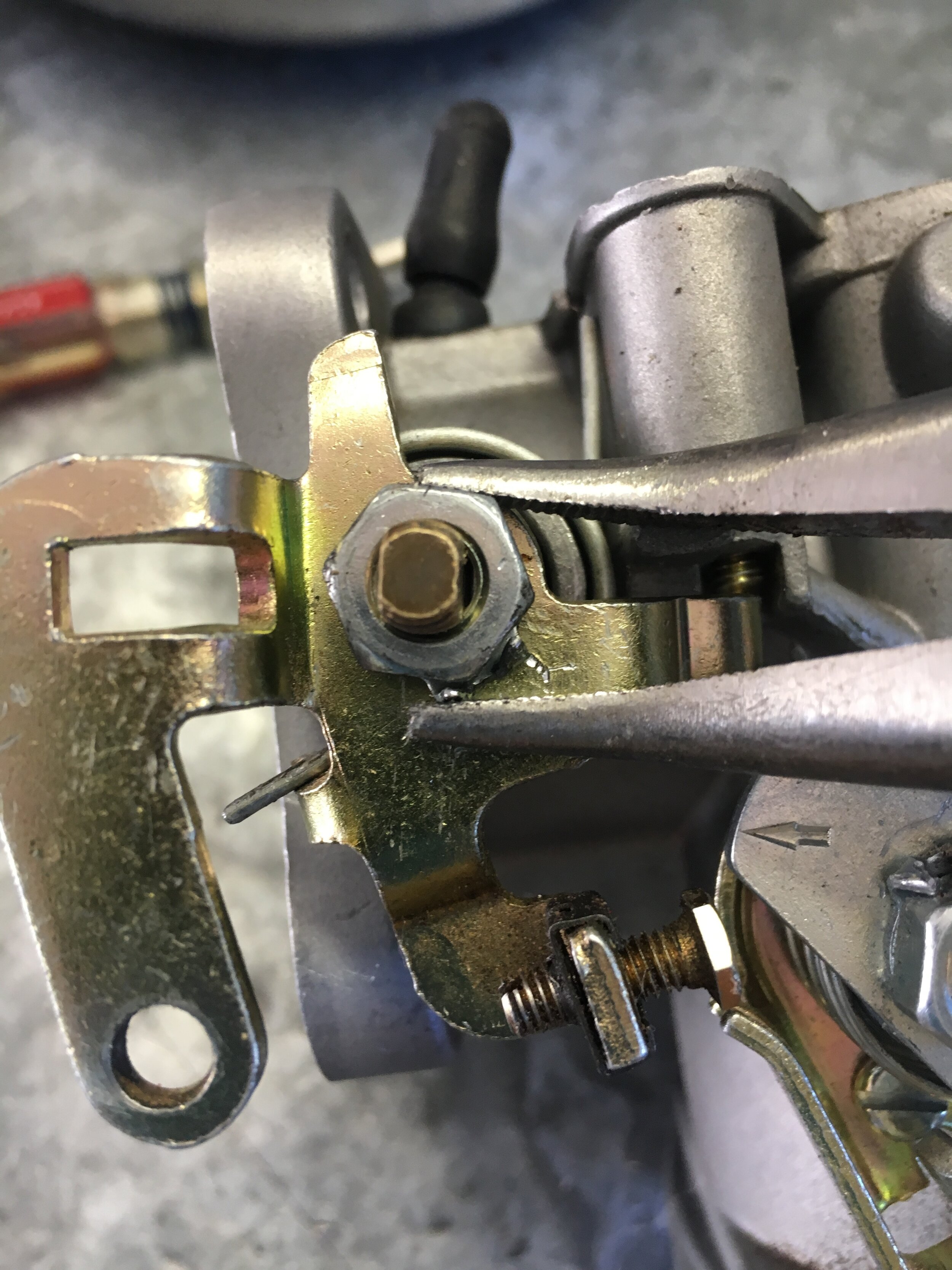
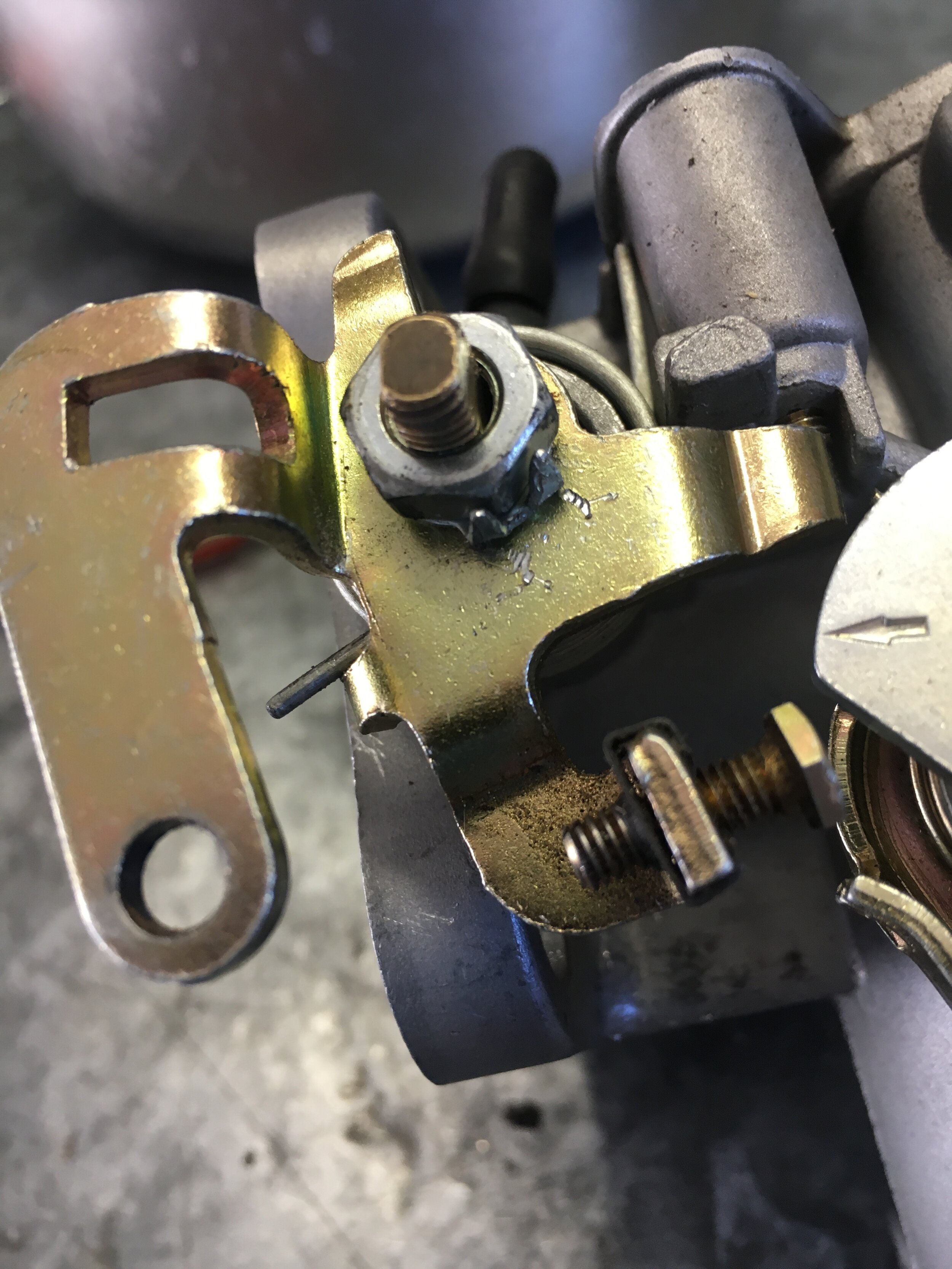
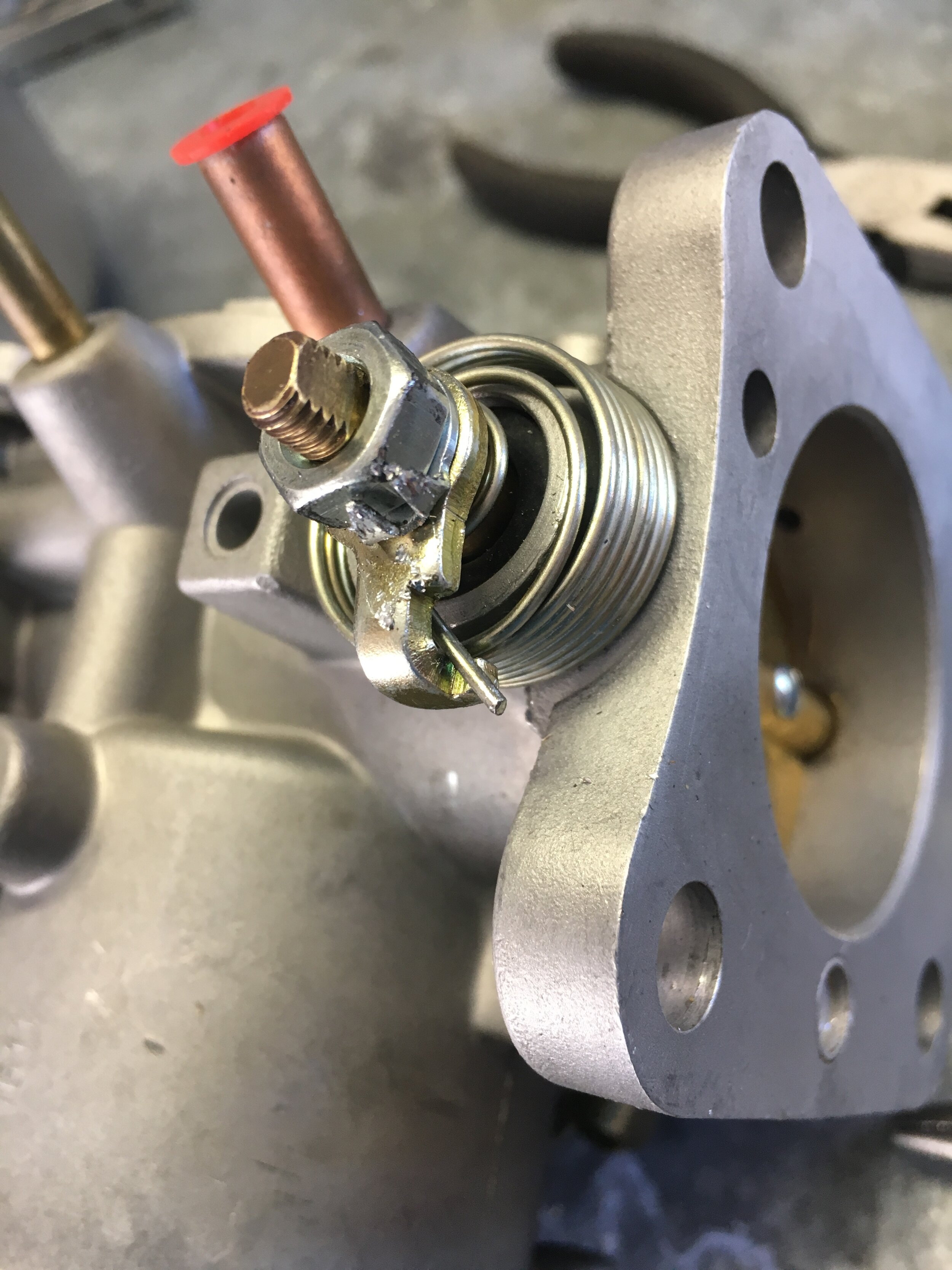
STEP 2 - Drill out the boost reference port.
When using the HIF44 carburetor (or any carburetor) in a ‘blow-through’ or pressurized system—as opposed to a draw-through setup—it is necessary to recreate low pressure inside the carburetor’s throat, so that fuel will be drawn through the Venturi or jet. You must take two steps to accomplish this.
First, you must slightly restrict the flow of air into the carburetor’s mouth without reducing its speed excessively or creating turbulence inside the carburetor’s throat behind the restriction.
We designed the world’s first ‘tunable’ snorkel adapter and ram pipe that accomplishes both objectives with interchangeable restrictor rings. The special adapter is pictured below and available on our purchase page:

Second, you must introduce boost into the float chamber.
In the MG Metro Turbo-spec HIF44 carburetor, there are two float chamber vents, as depicted by the dark blue arrows in this photo:

In the standard-spec HIF44 carburetor used in this conversion, there is only a single float chamber vent, corresponding to the upper vent in the Metro Turbo-spec version. The lower vent is closed off with a cap pressed-in at the factory, as shown below (the vacuum chamber is removed in this photo):

In lieu of the Turbo-spec carburetor’s drilled passage connecting the float chamber vent circuit to the intake plenum or snorkel, you may do one of two things.
Option one—not the preferred route—is to insert a ‘Y’ or ‘T’ fitting into the vent hose as close to the carburetor as practical (not shown in the above photo). You then will connect one of the two hoses coming from the ‘Y’ or ‘T’ fitting to the intake plenum or snorkel, as close to the carburetor’s throat as practical. The other should be routed as with any other carburetor float chamber vent—with one exception noted at the end of this step.
Option two—and much preferable—is to open up the boost reference port by drilling out the horizontal cast channel. This is very straightforward, and merely involves drilling through a thin wall in the casting (you do not even need to oil your drill bit). Below are photos and notes to guide you through the process.
First, take note that your goal is connecting the float chamber vent (first photo) to the blanked-off boost reference port the face of the carburetor (second photo), via an unused, horizontal channel in the carburetor casting (third photo):
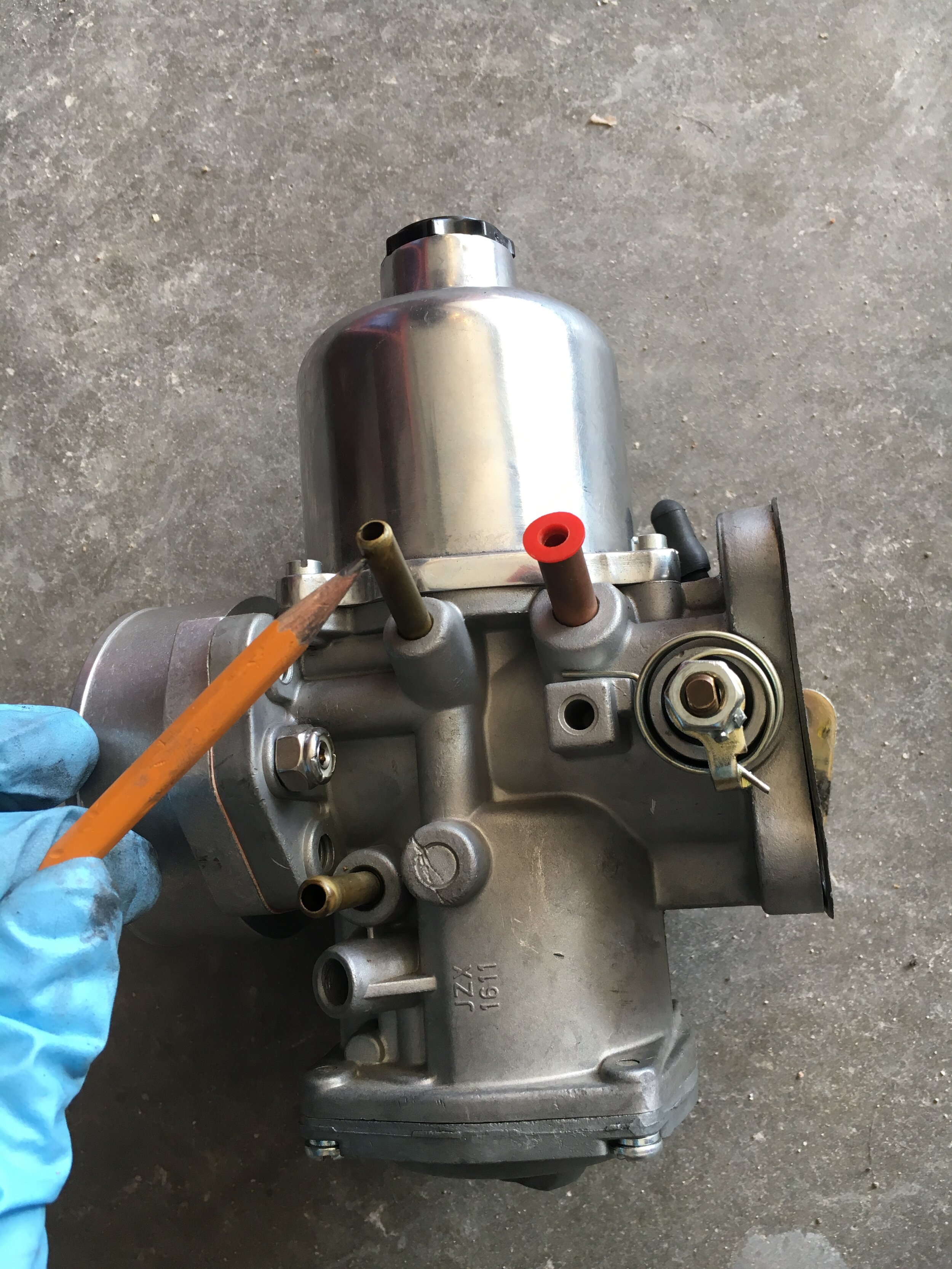
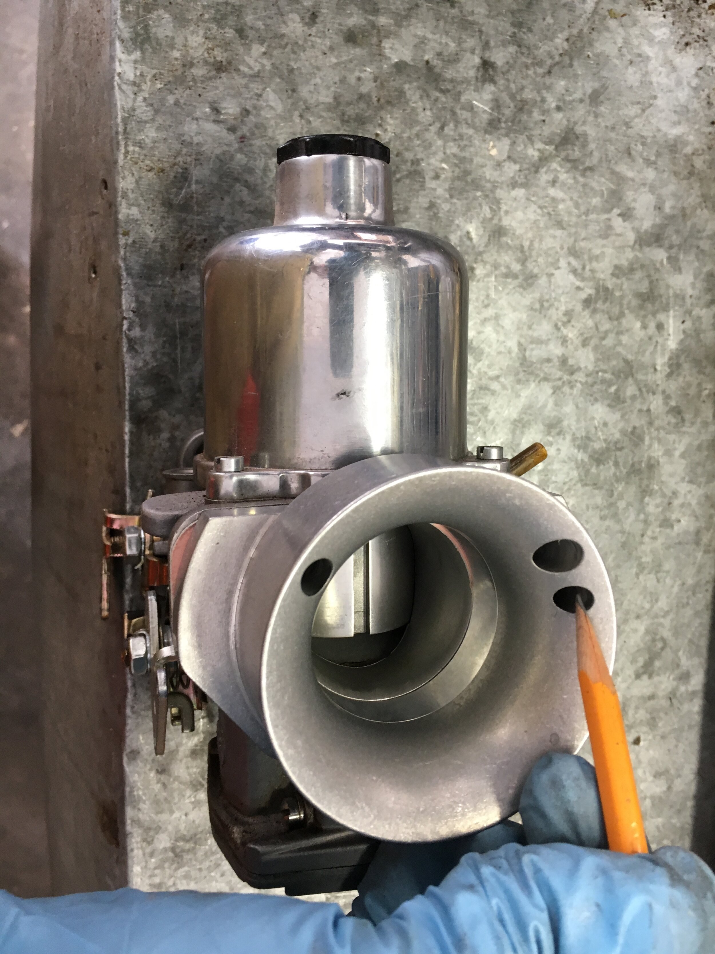

Second, remove the vacuum chamber and piston and set them aside:

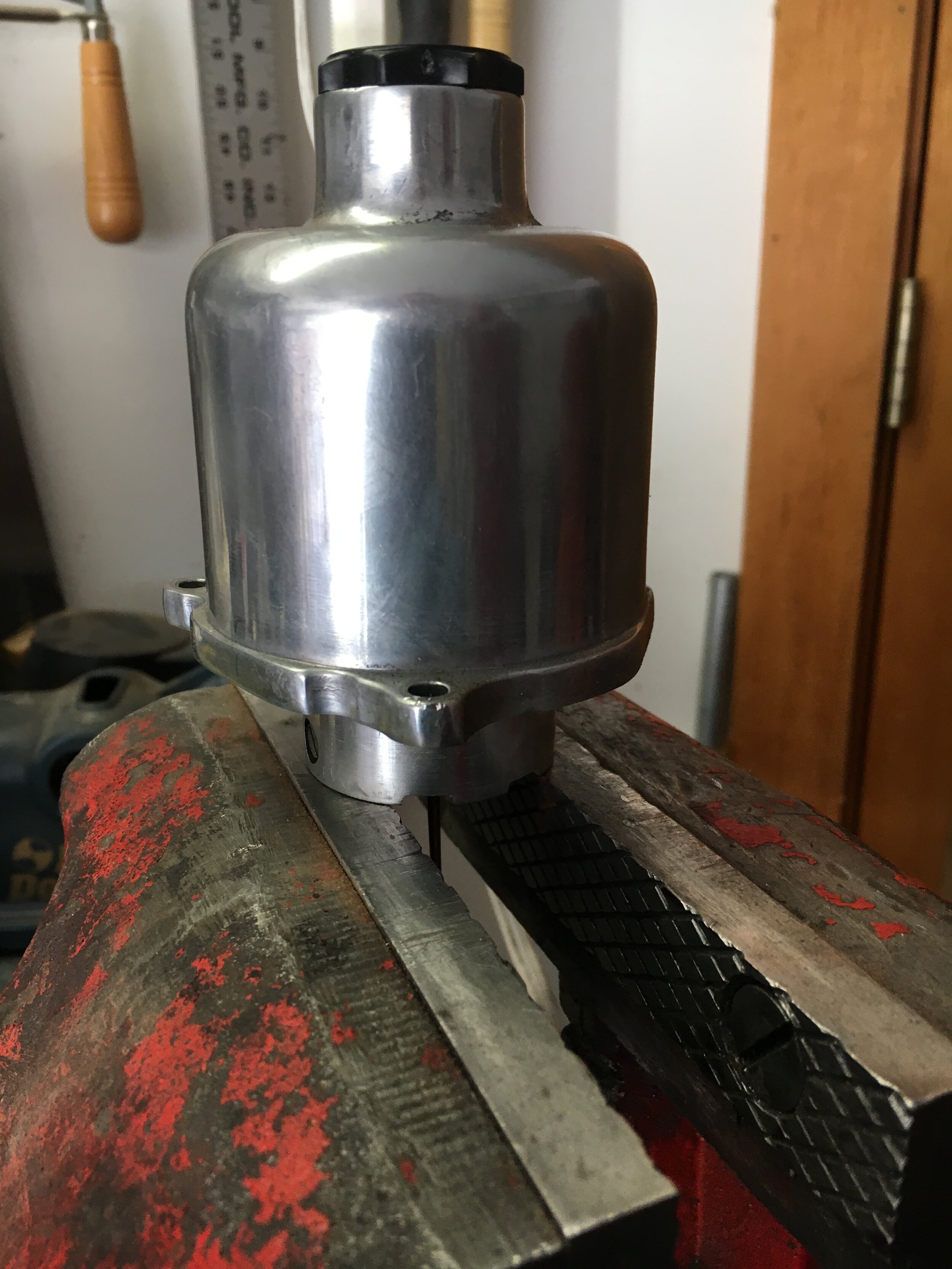
Third, remove the four screws and lock washers holding on the float chamber cover. Check the rubber O-ring for damage or rot and replace accordingly:
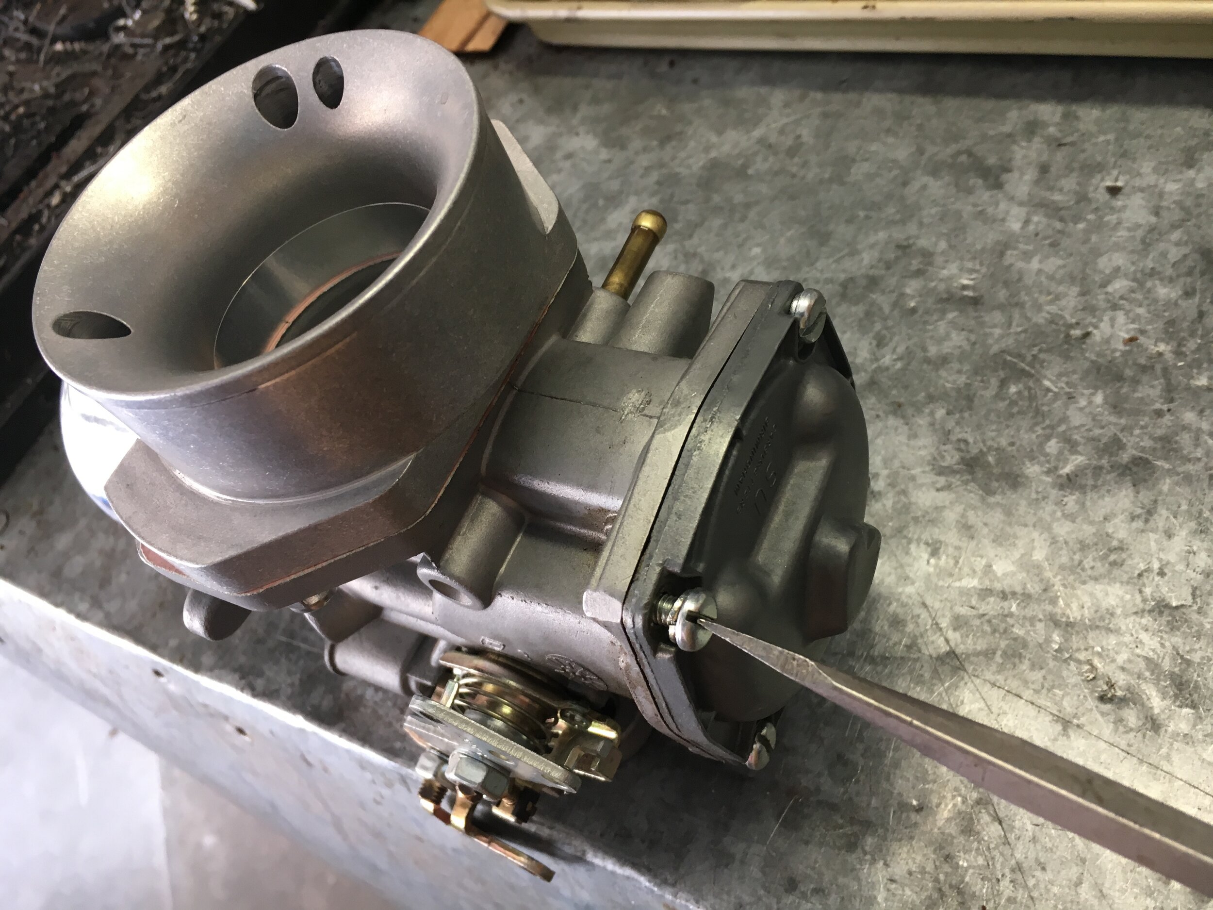
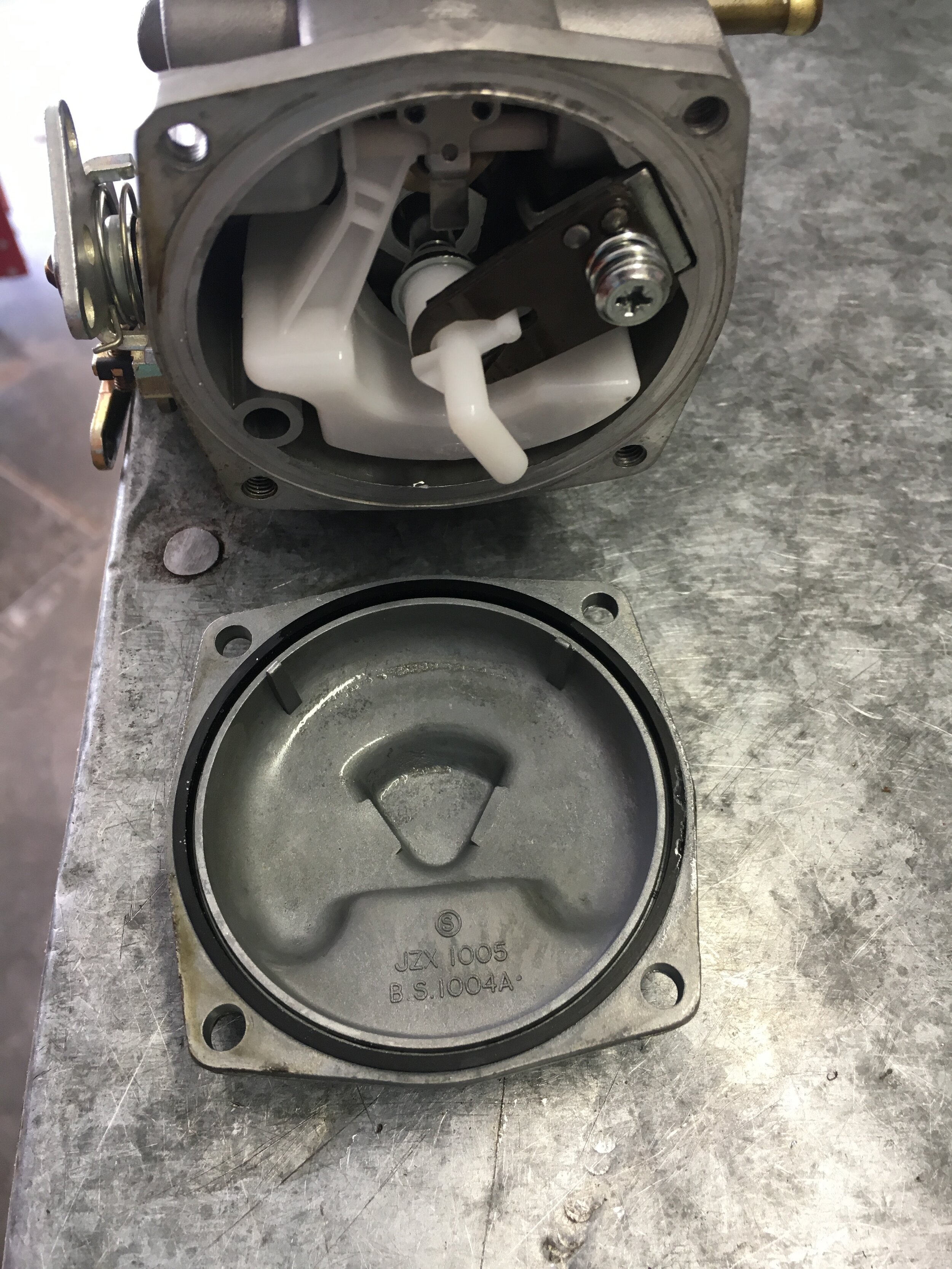
Fourth, remove the float pivot screw, carefully remove the float, and set it aside:
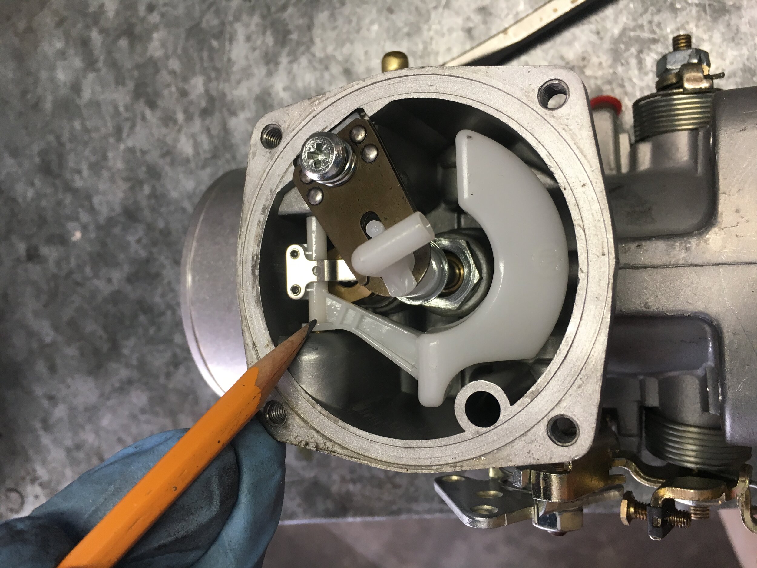
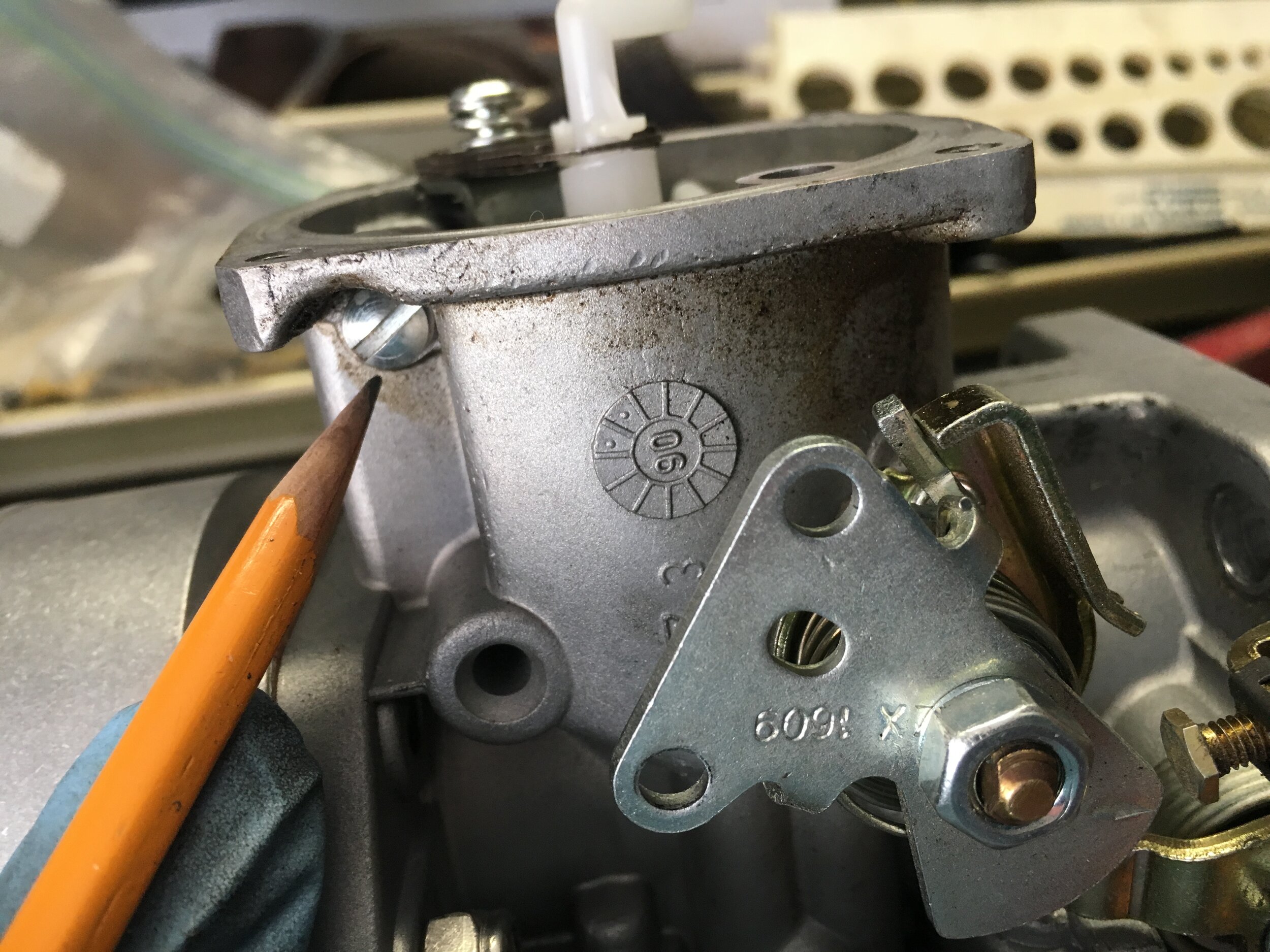
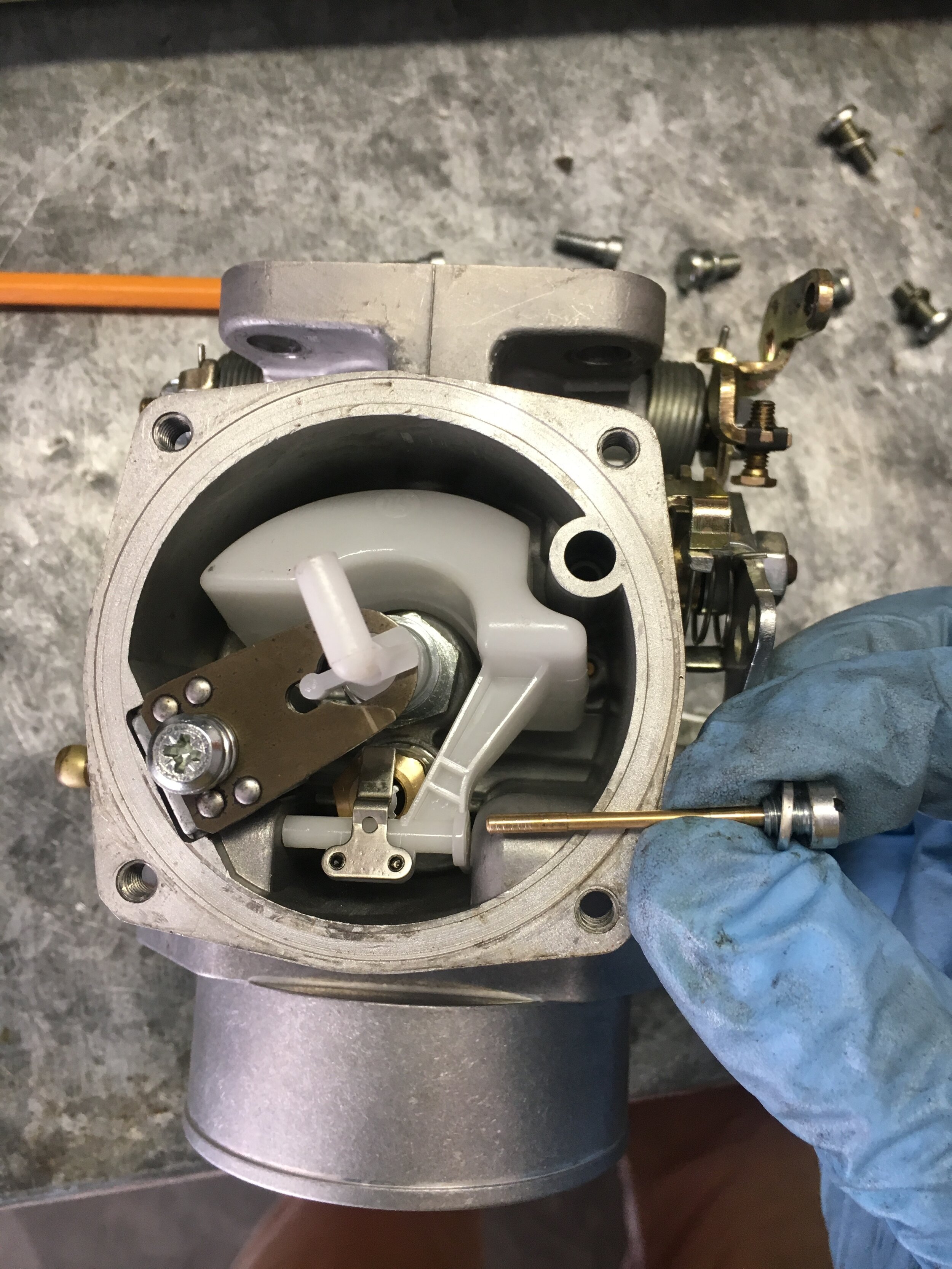
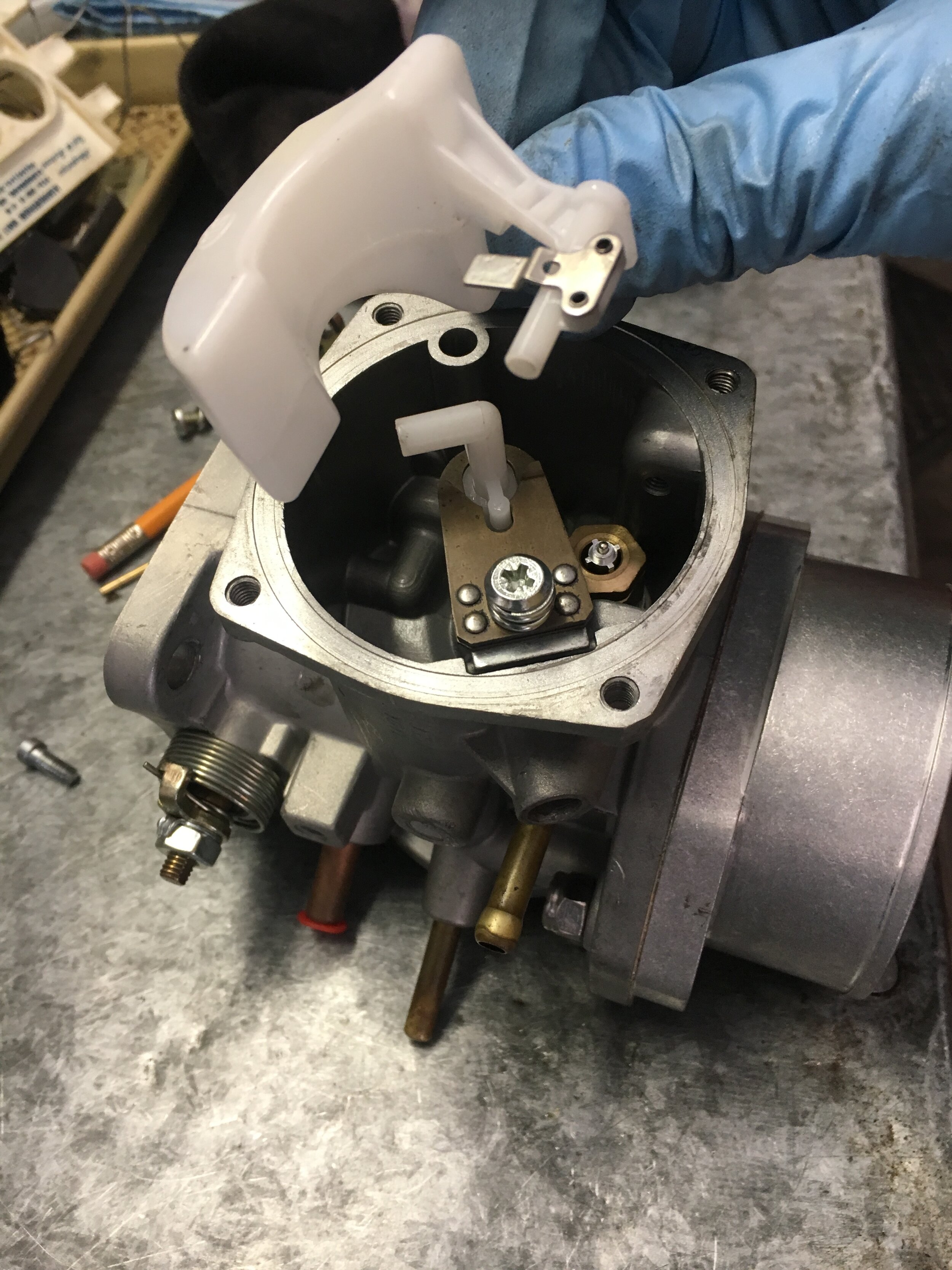
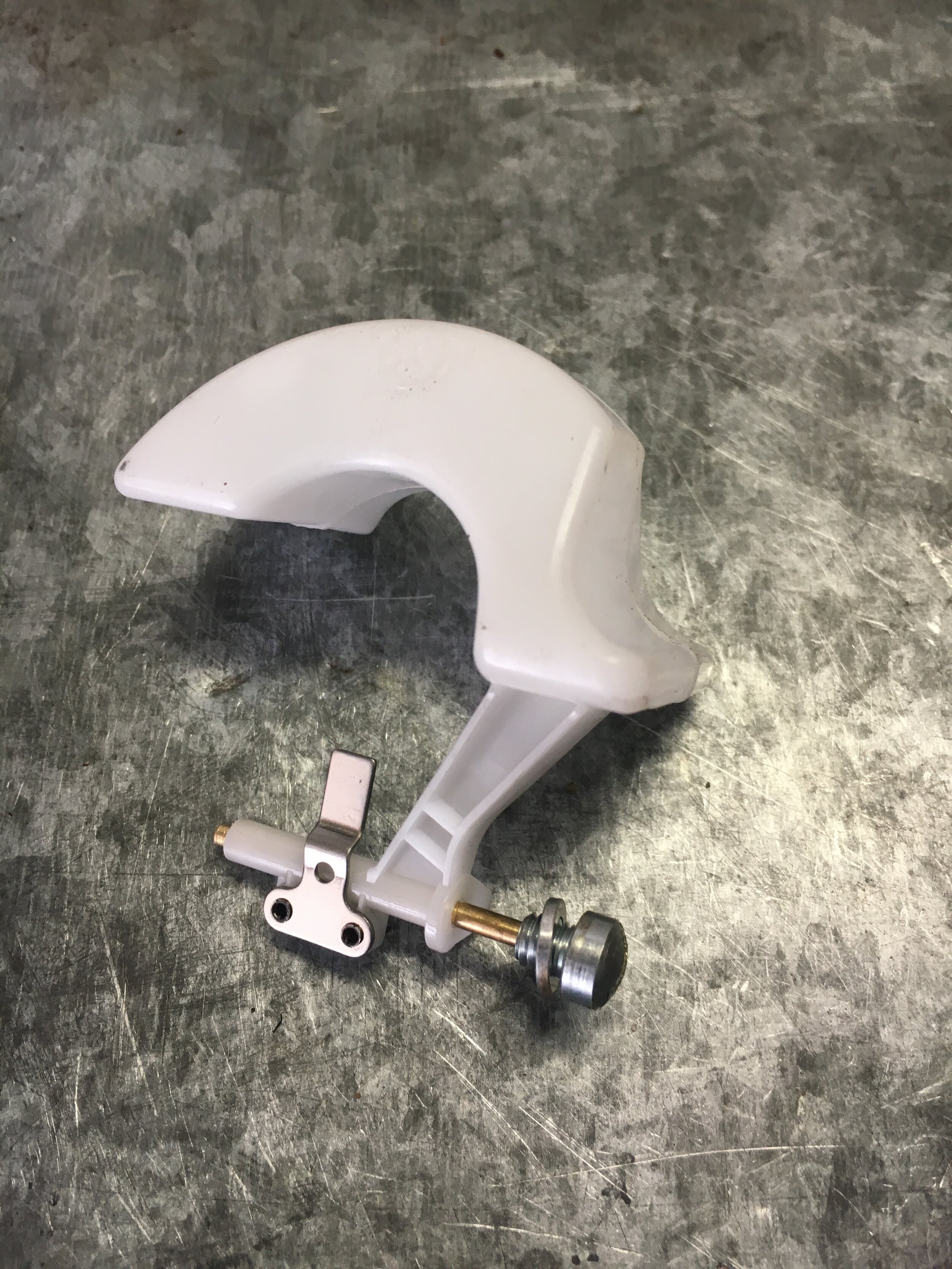
Fifth, remove the spring-loaded, jet retaining screw and gently lift the jet out and set it aside. Note the jet adjustment screw in the third photo, to which you must pay close attention upon reassembly:
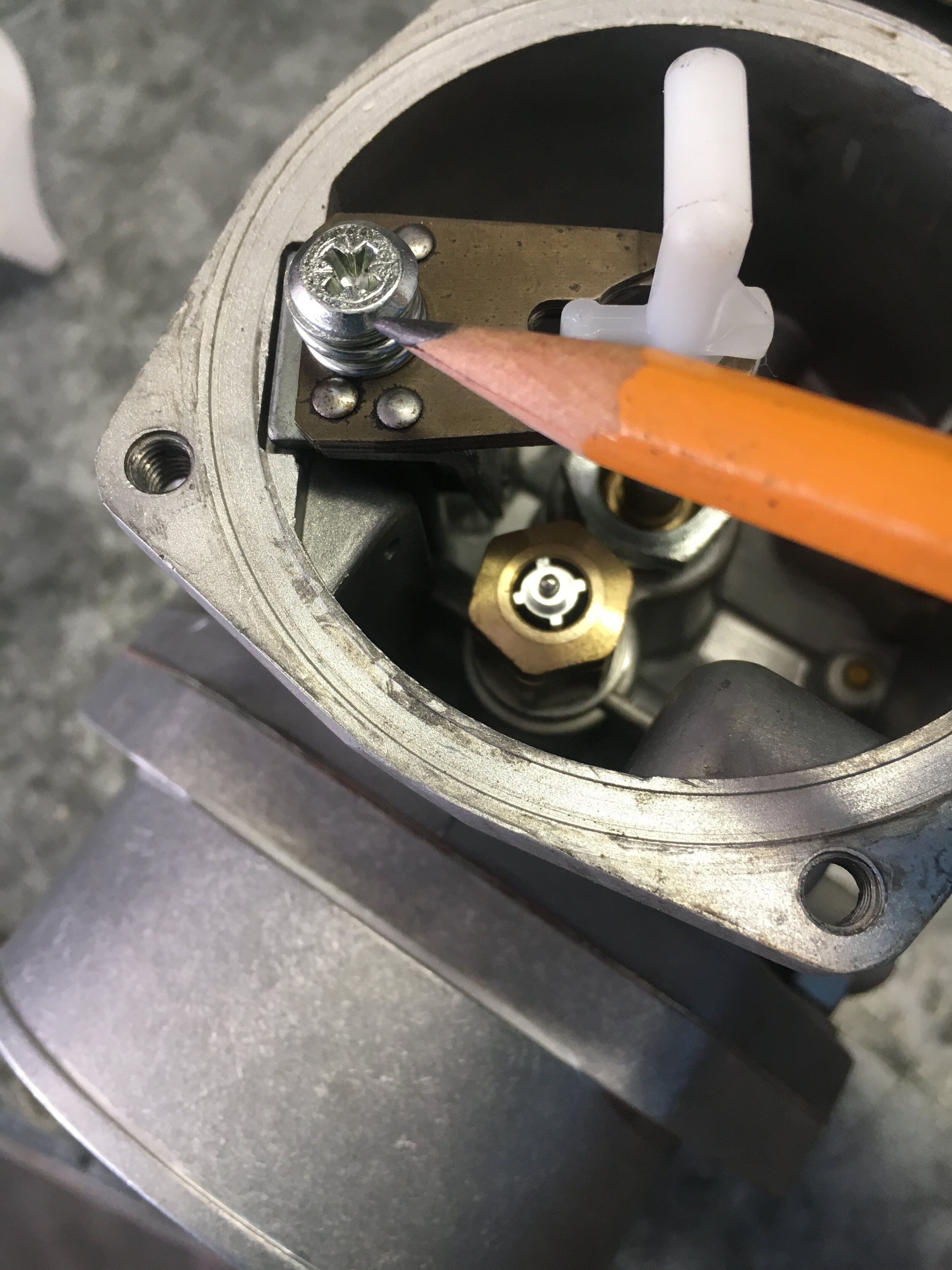
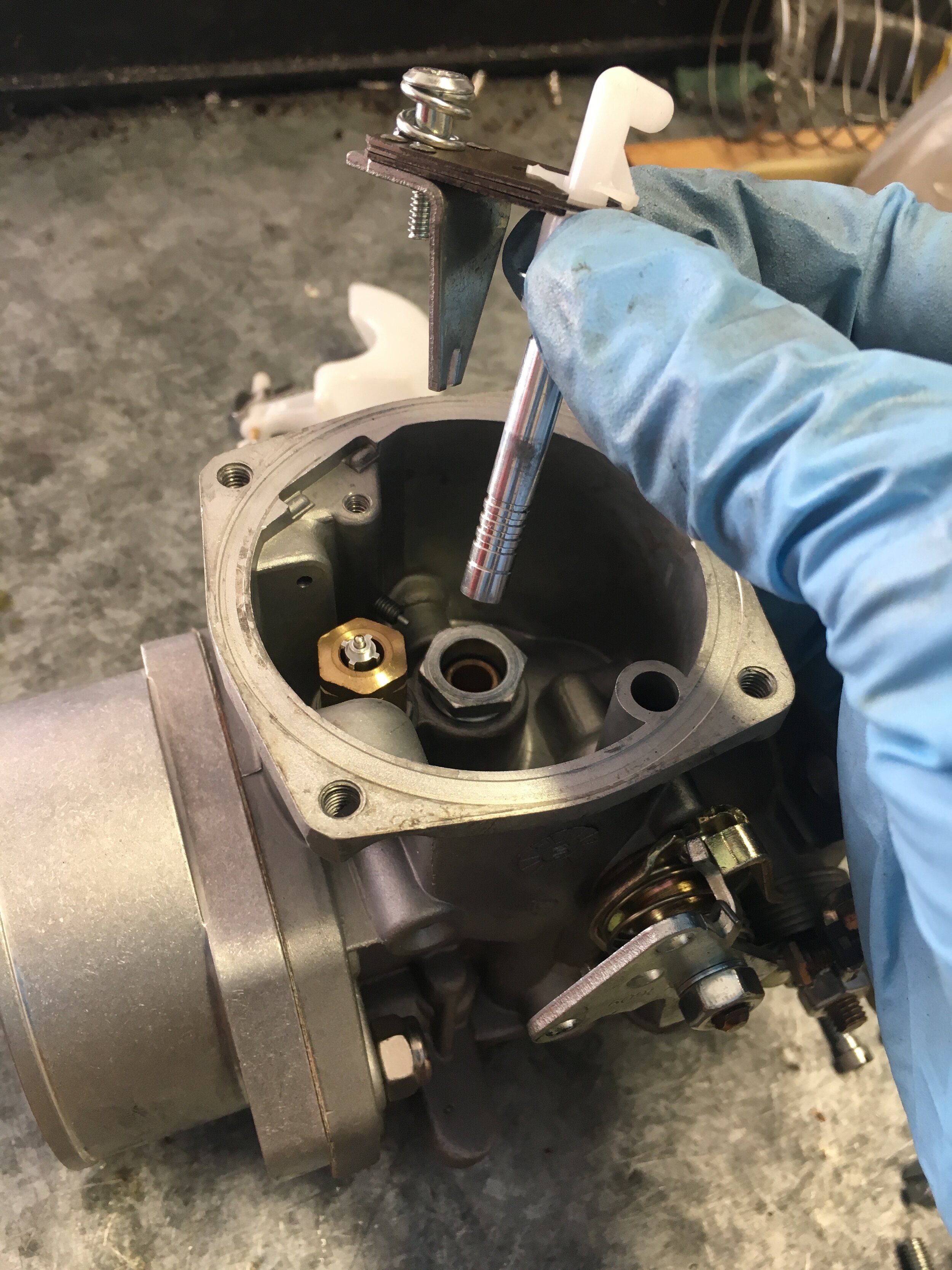
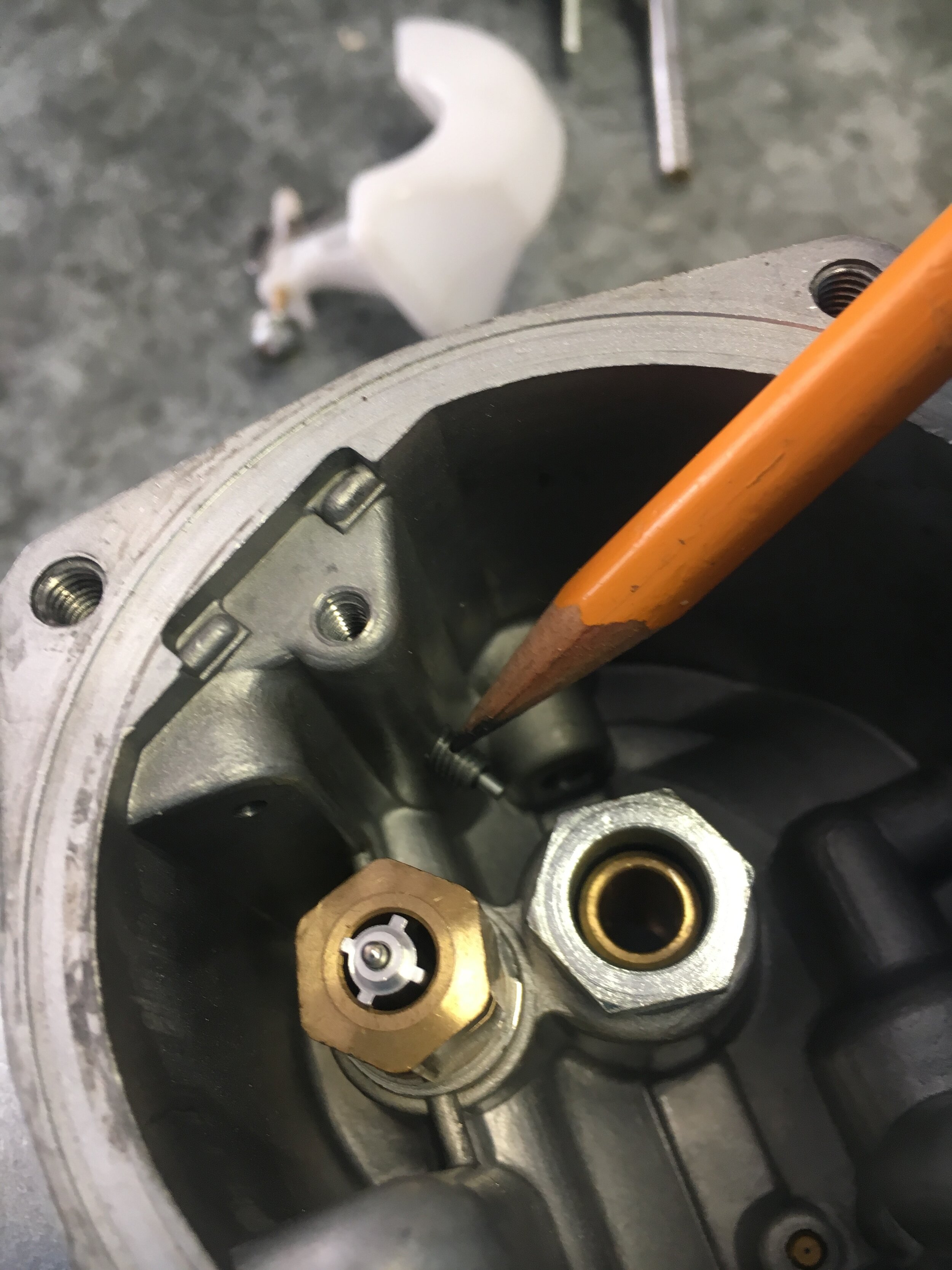
Sixth, using a 1/2” socket, remove the jet together with the Viton-tipped needle valve, and set aside. Note that there is a brass mesh filter beneath the needle valve that you will have to remove with tweezers or by inverting the carburetor. Ours was distorted, presumably due to hasty assembly by the rebuilder:
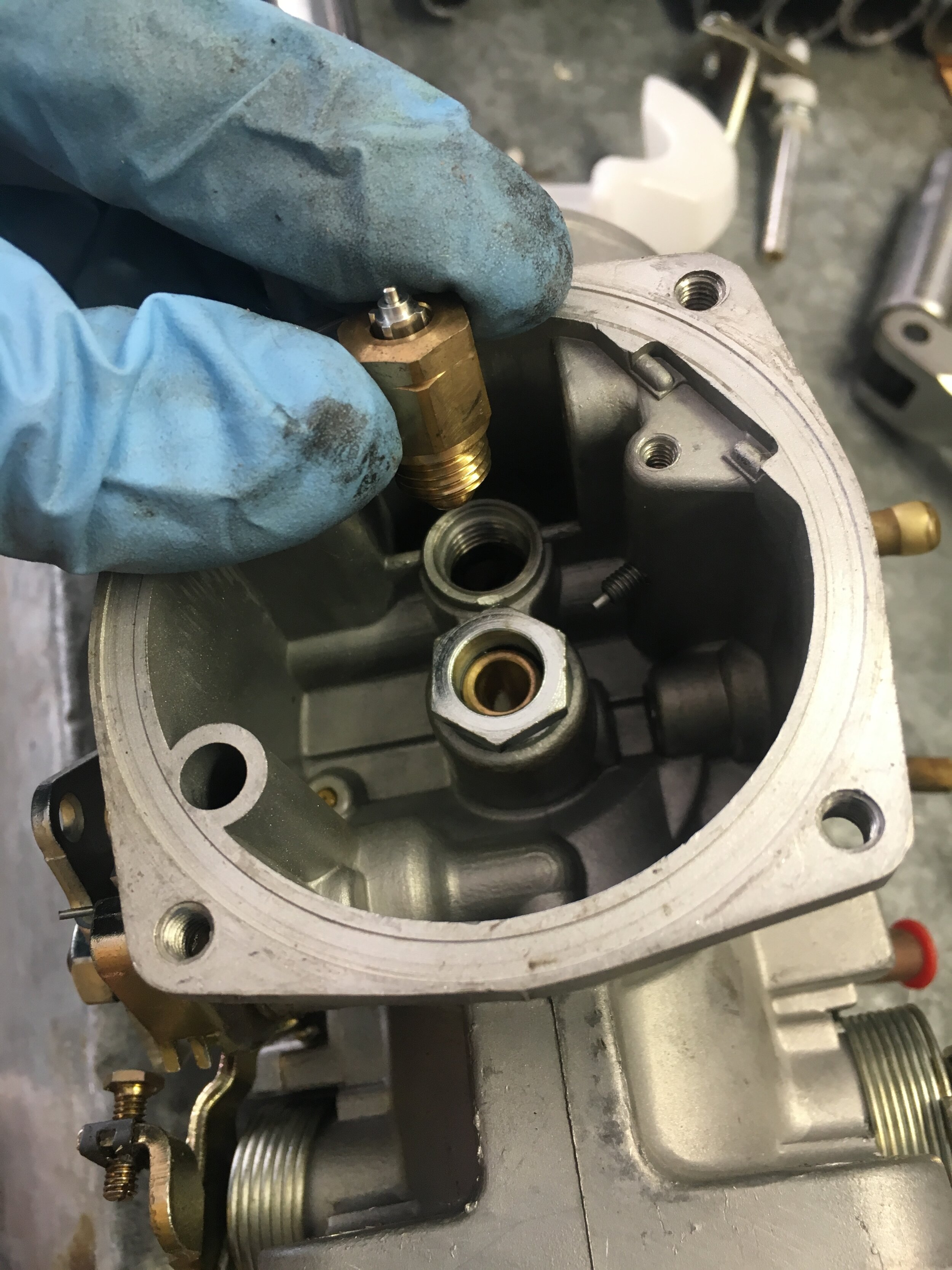
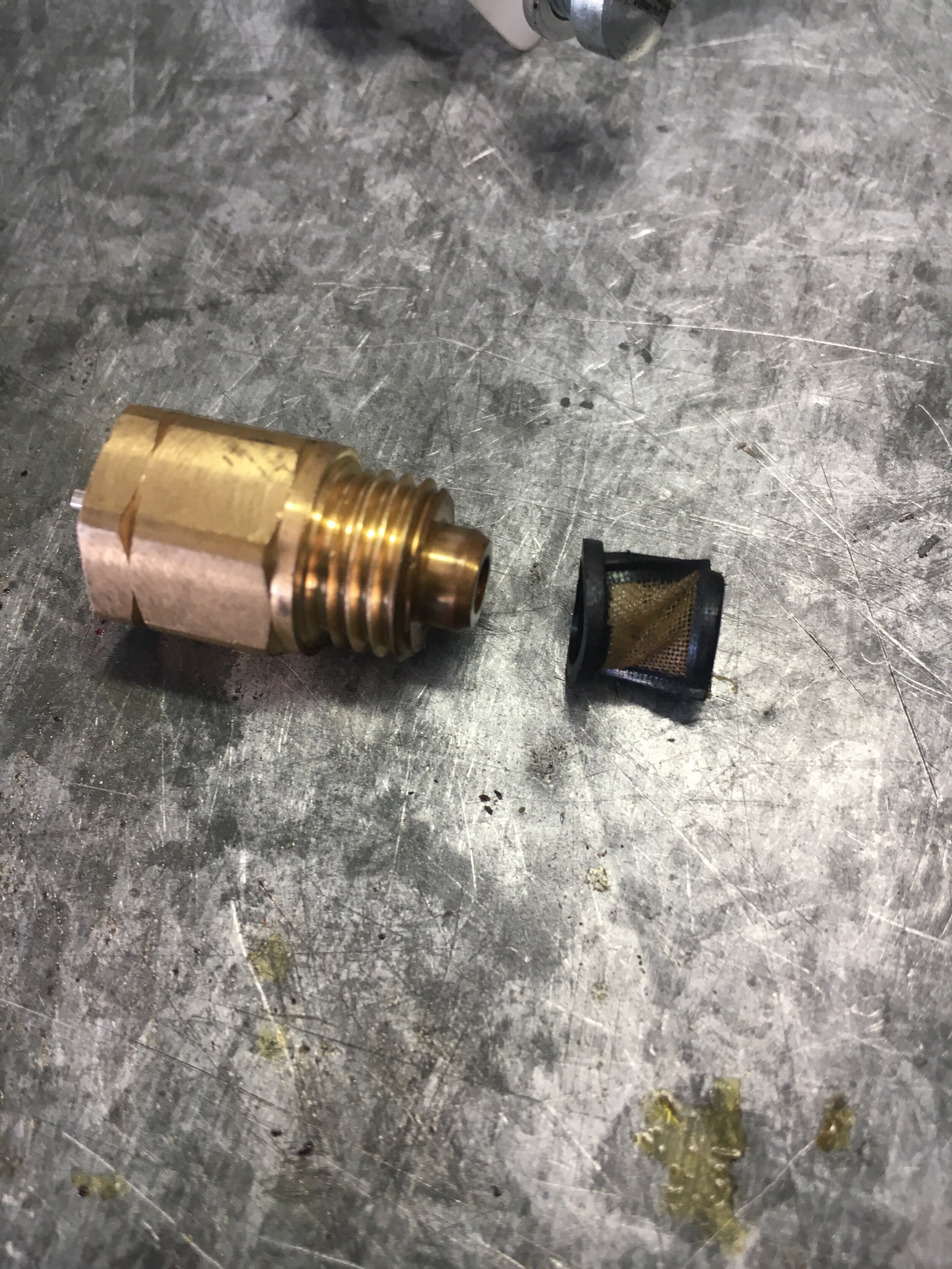
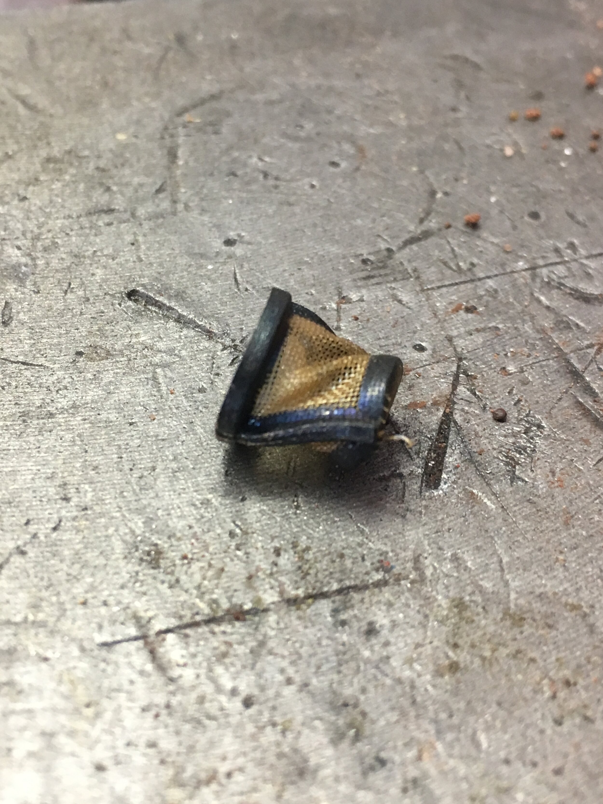
Seventh, now that the float chamber is emptied of its components, take a moment to orient yourself by blowing through the vent and locating its terminus inside the float chamber:

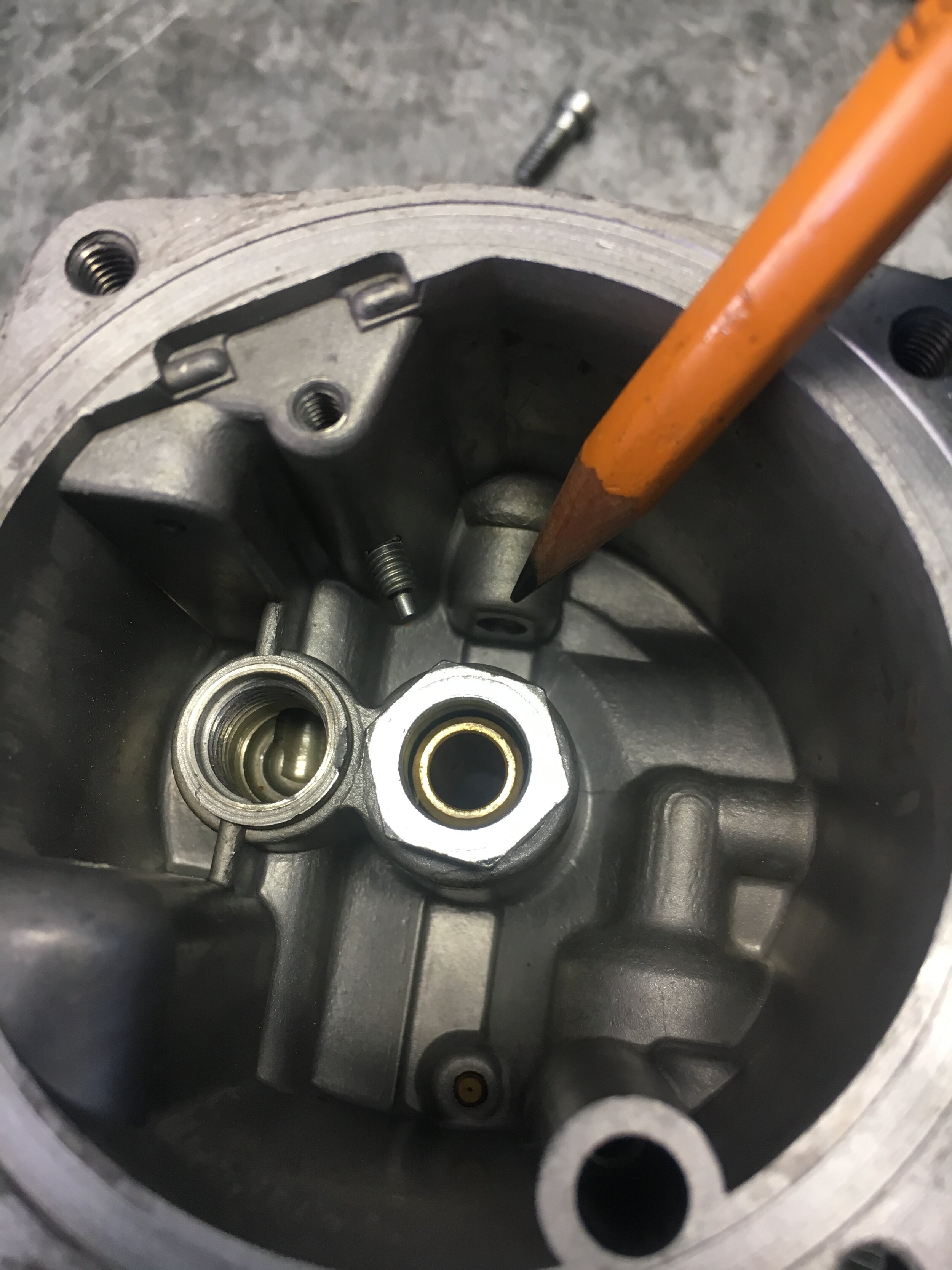
Note again that your objective is to connect the vertical vent in the casting to the horizontal vent leading to the carburetor’s face:
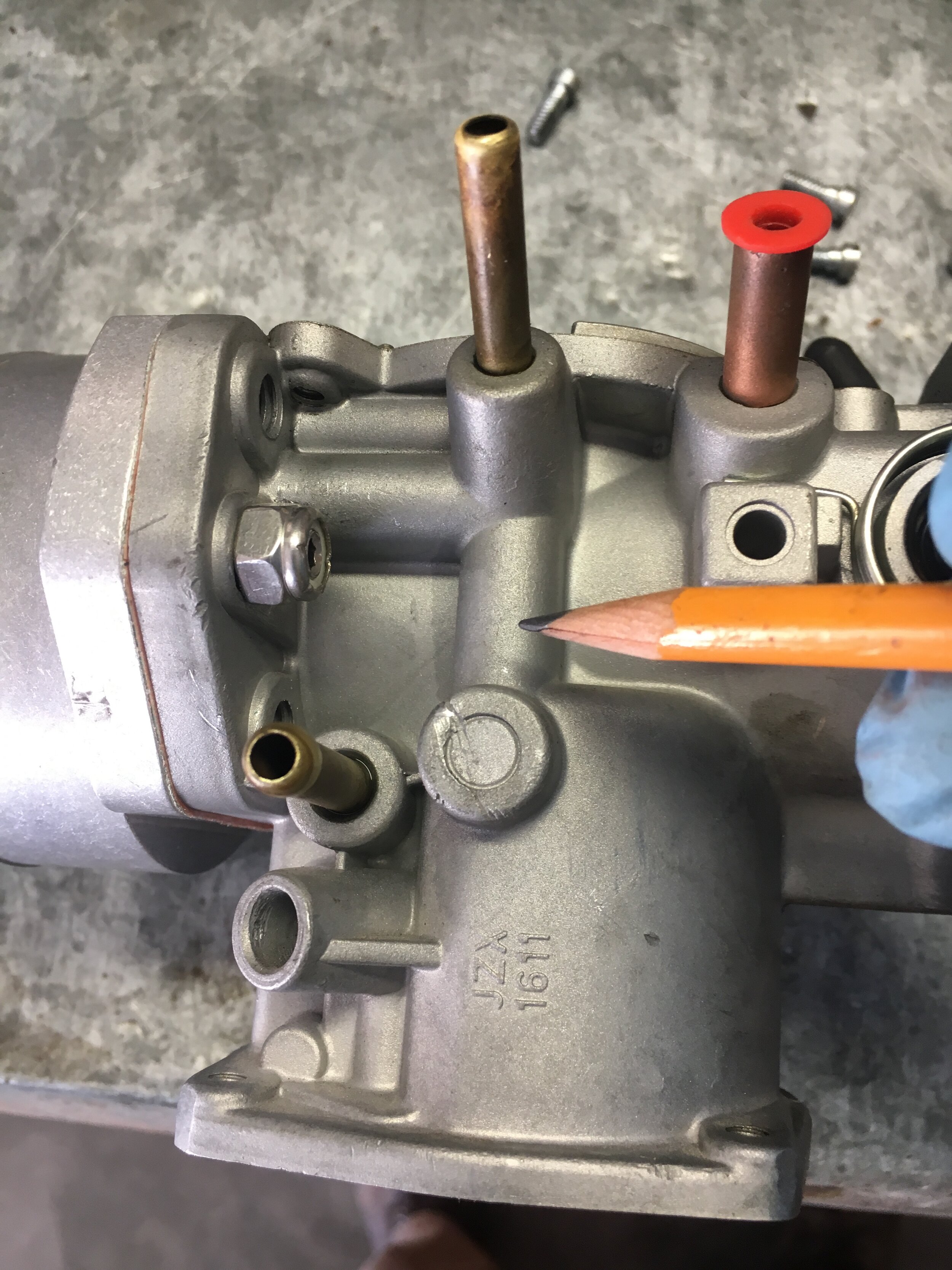
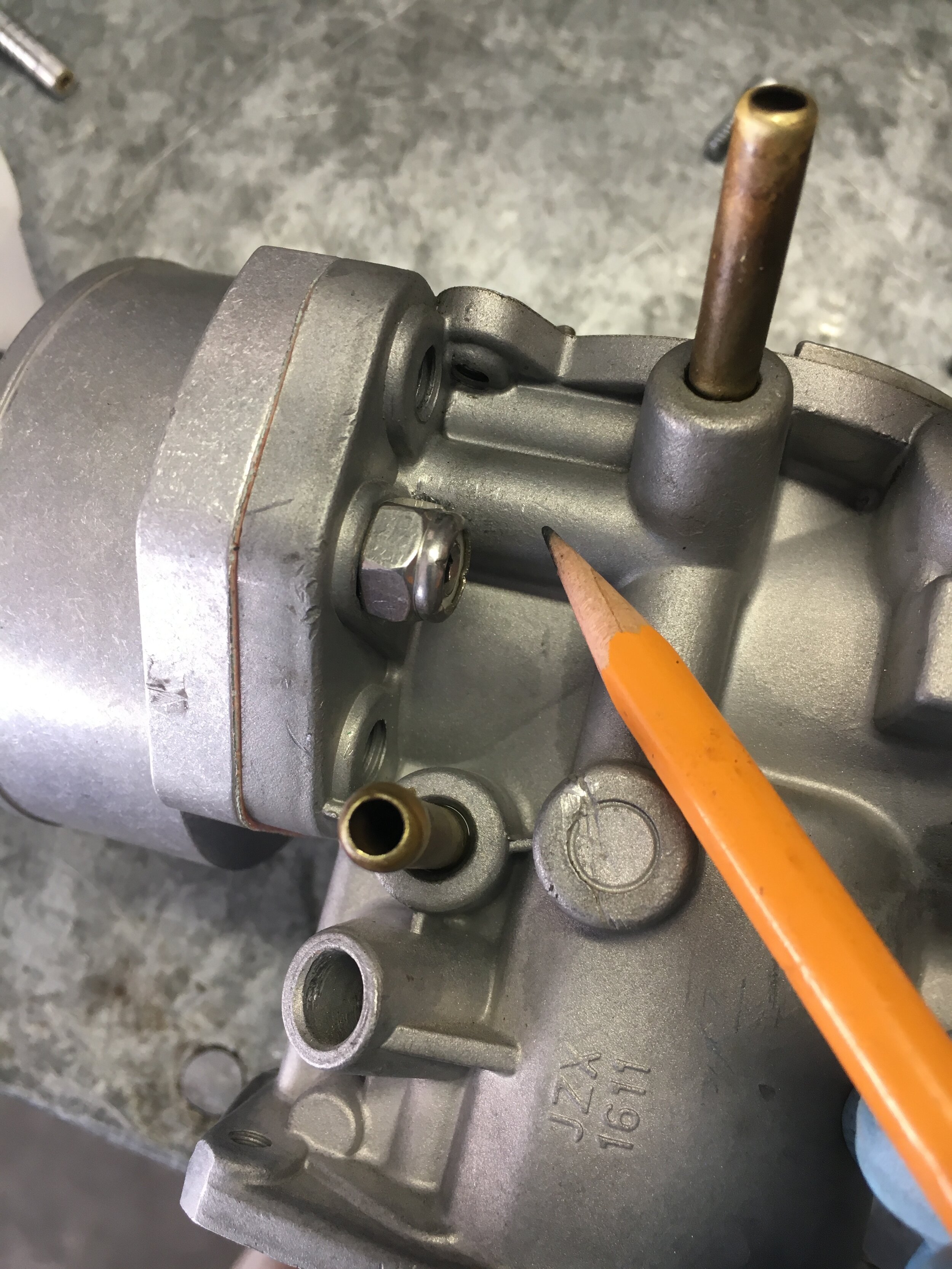
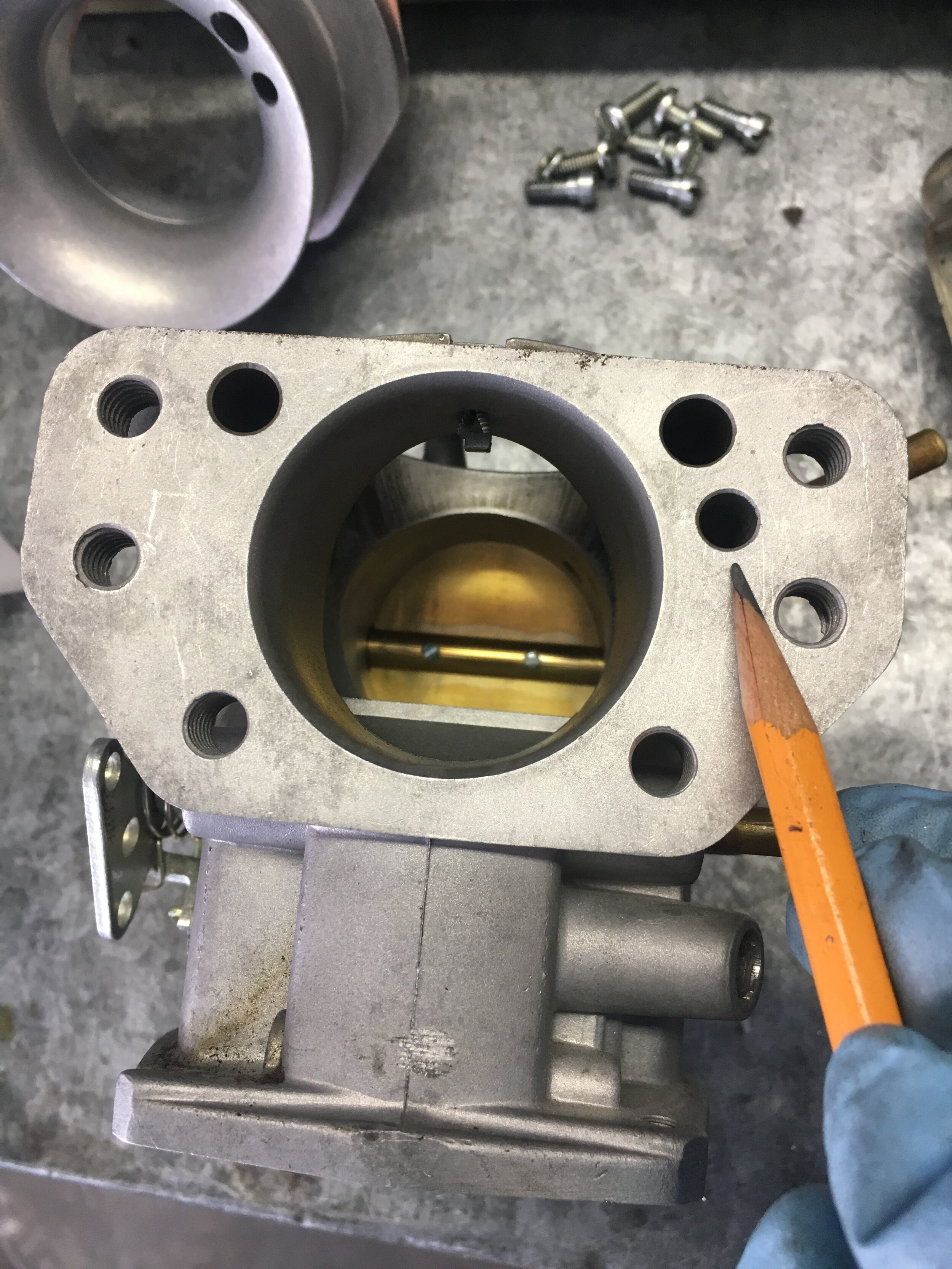
You can see in the next image the depth of the existing, blanked-off passage in the casting, as measured from the face of the carburetor. There is very little material to drill through to reach the vertical passage, and the alloy is quite soft:

Eighth, using a 7/64” drill bit, drill through the bottom of the horizontal passage from the face of the carburetor (air cleaner side) inward toward the vertical vent. We initially centered the carburetor body on the drill press using a 15/64” bit, but after probing the cast passage, realized that its bottom is roughly conical, such that the 7/64” bit would likely center itself.
Indeed, you may not need a drill press at all, and we used one merely because it was handy. In any case, make sure you dump the shavings out through the horizontal passage in the face of the carburetor:

Ninth, reassemble the carburetor in reverse order, taking care to fit the slot in the jet adjustment plate onto the adjustment screw—whose setting you should not have disturbed during disassembly:

The float chamber cover only goes on one way: the following image shows the orientation of the relief for the jet pickup tube. The recess in the cast cover should point like an arrow toward the face (air cleaner side) of the carburetor:

Finally, install the Creative Spridgets ‘tunable’ snorkel adapter and ram pipe, taking care that you use a gasket which has a passage to accommodate the boost reference port you have now made active:
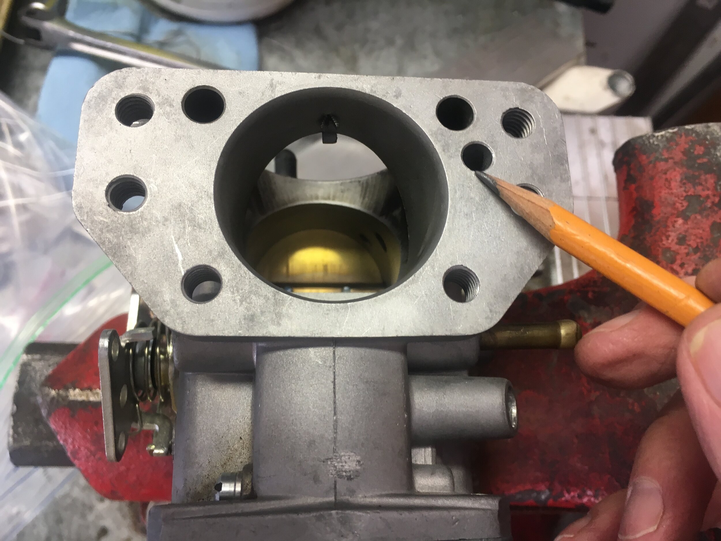
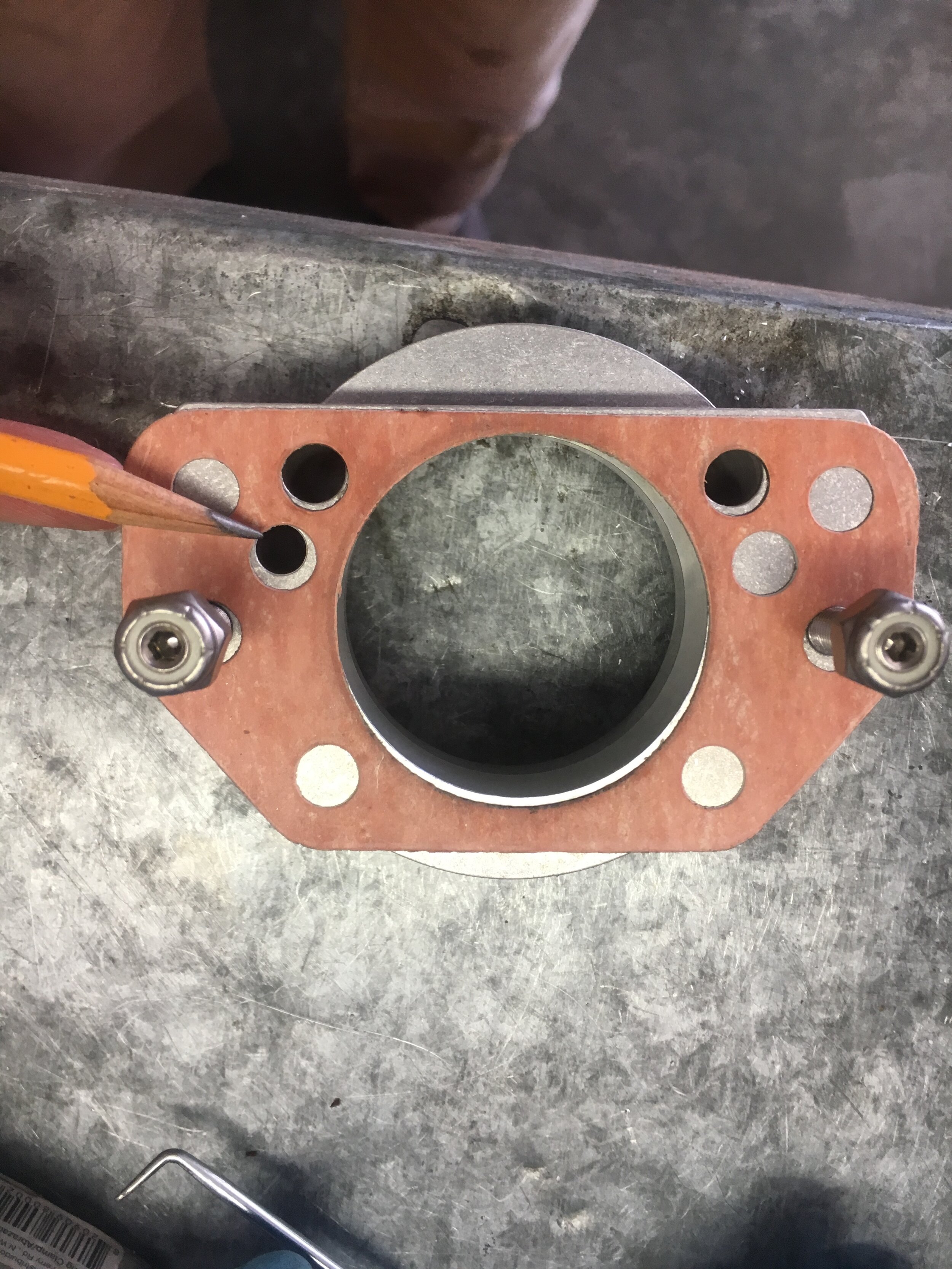
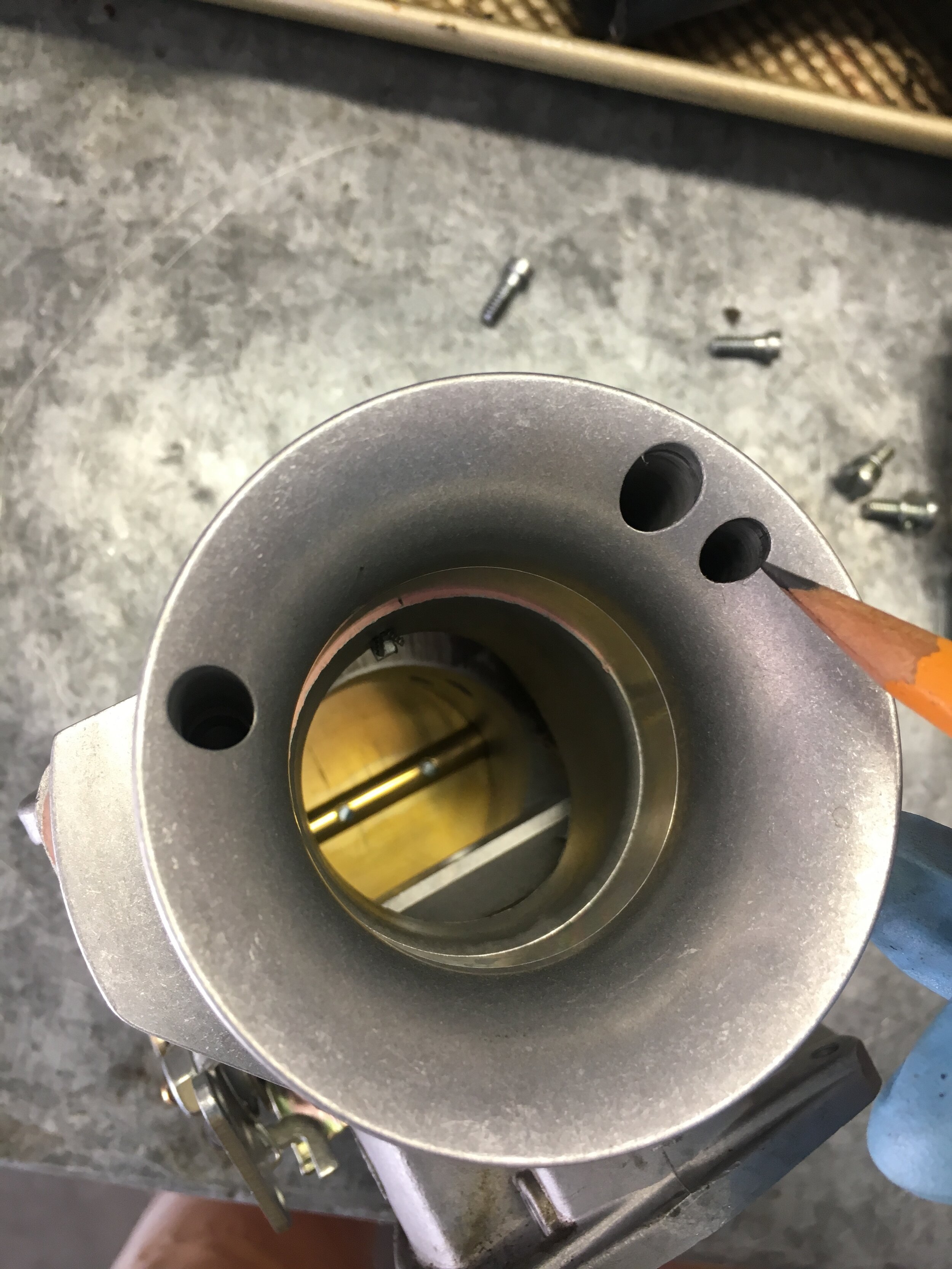
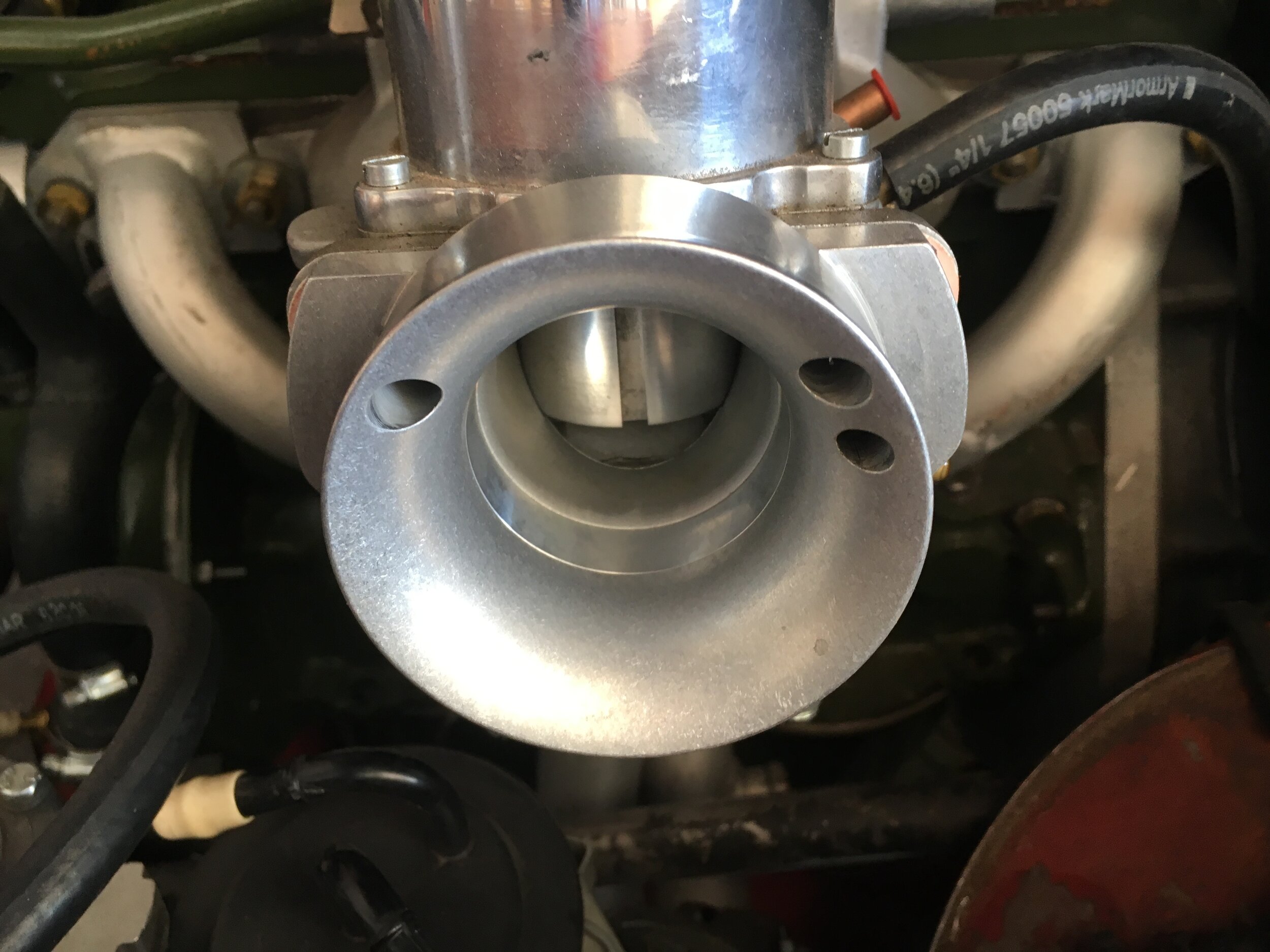
STEP 3 - Plumb the float chamber vent hose.
The float chamber vent hose must include a one-way valve, oriented to allow air into the float chamber when the engine is running under vacuum (idle, steady-state cruising, or trailing throttle), but to prevent pressure from escaping when the engine is under boost.
An inexpensive valve, ACDelco 14047619, is in the parts list and is pictured here:

The first and second images below show where it may be installed in the vent hose. The third and forth images show the brass Tee fitting for the boost reference line to the ‘rising rate’ fuel pressure regulator.
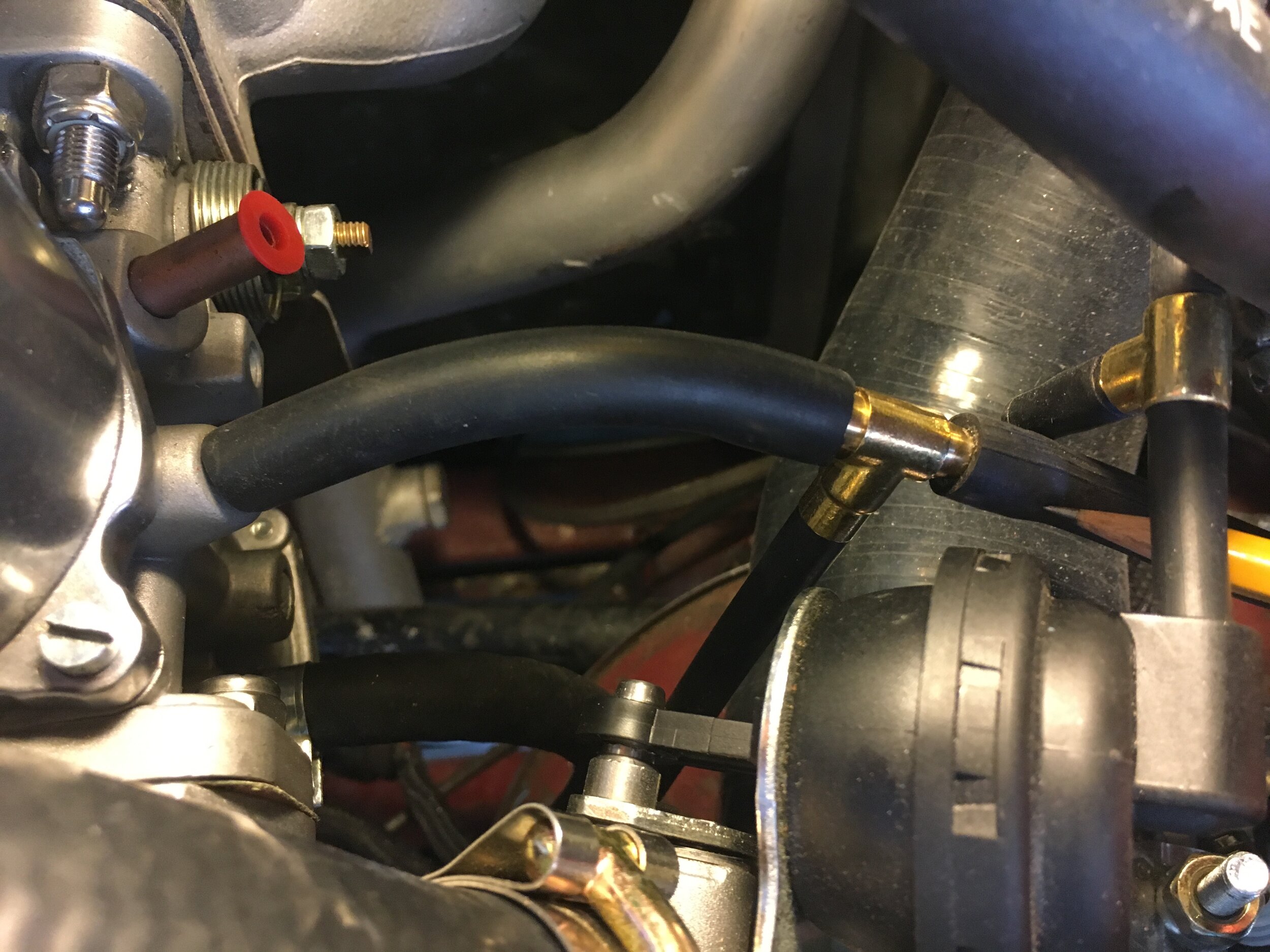
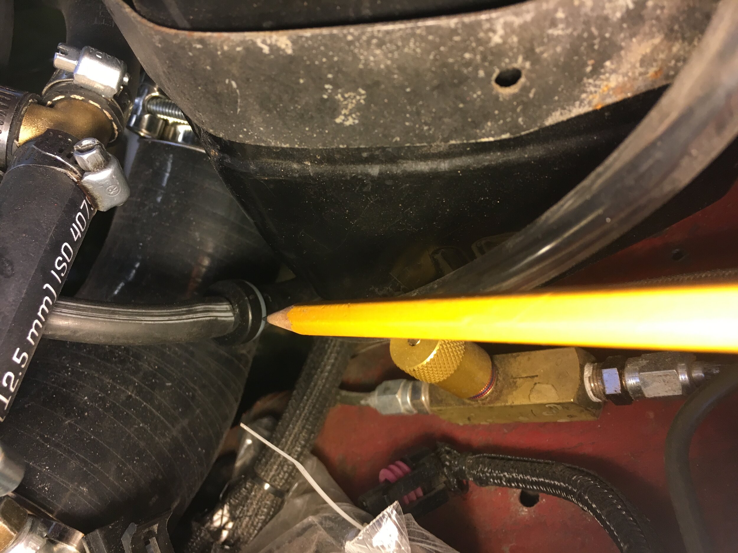
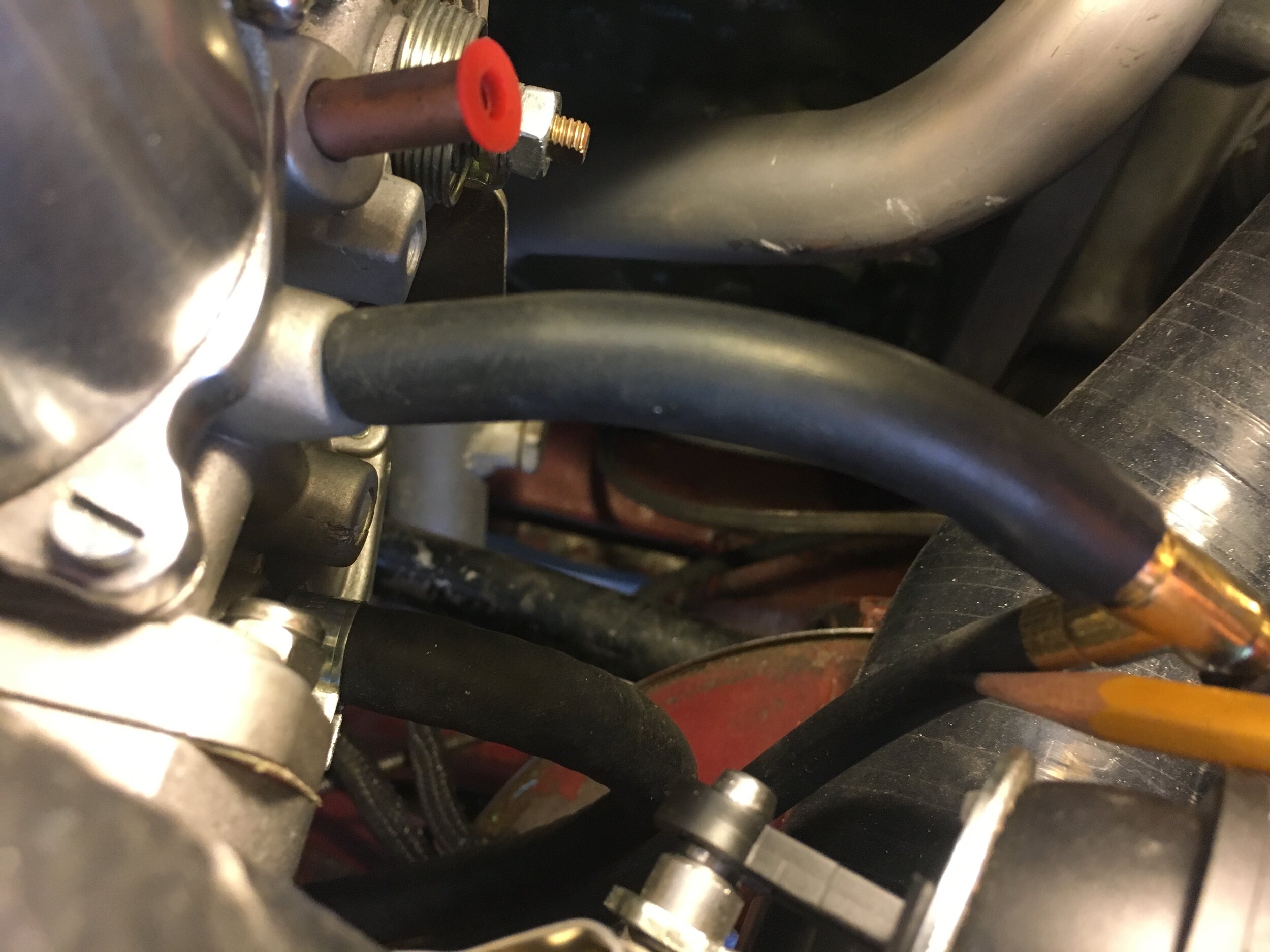
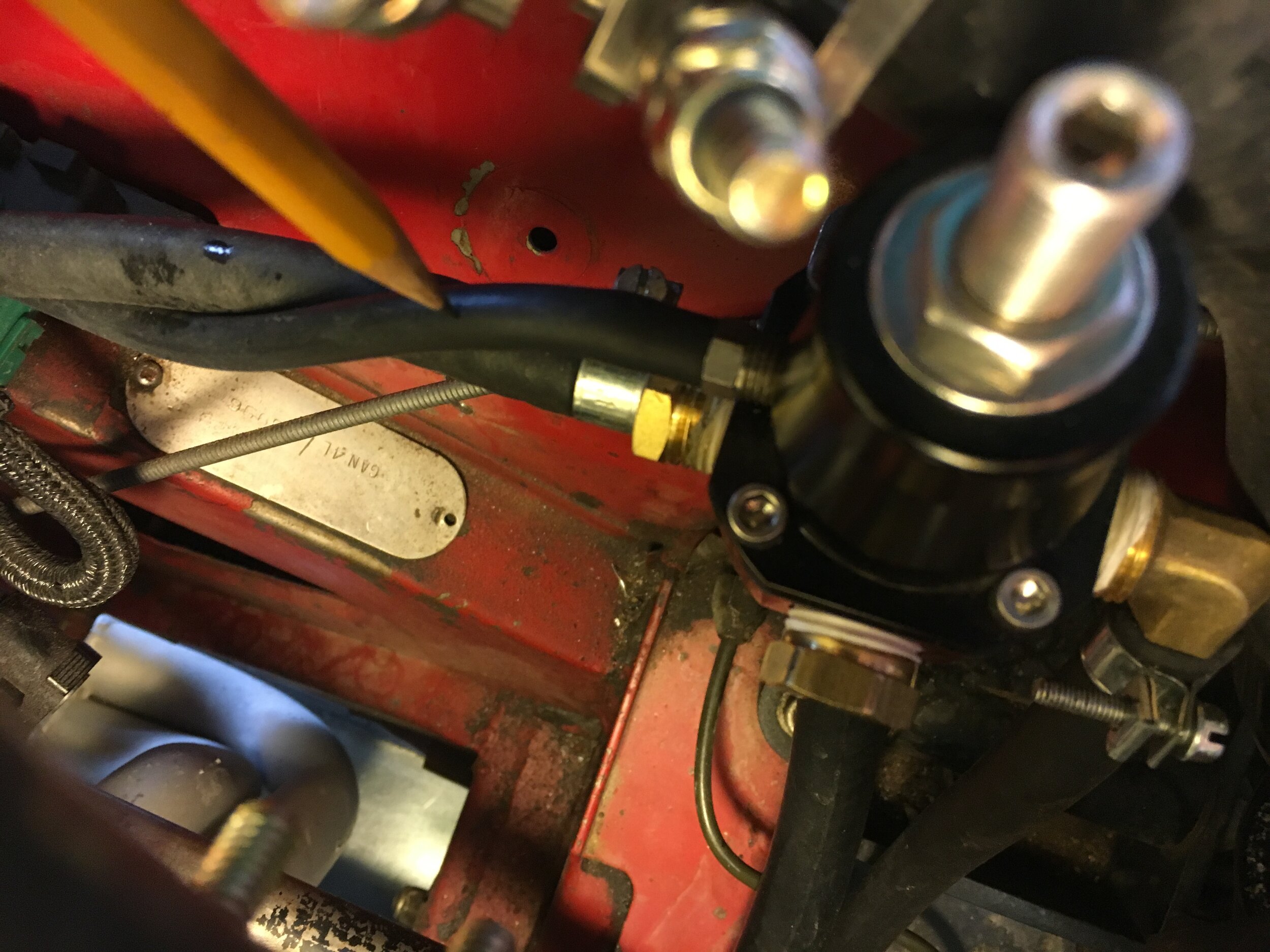
STEP 4 - Seal the vacuum chamber
The Turbo Metro-spec HIF44’s casting incorporates a groove to accept an O-ring style gasket, as shown in the below left photo. Compare with the standard-spec HIF44 to the right:
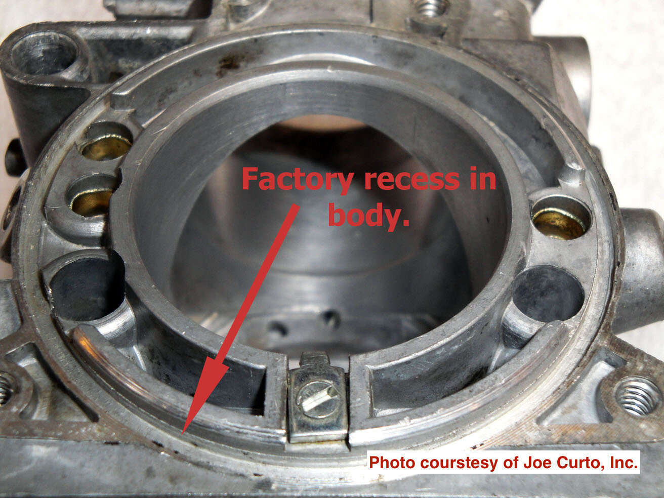
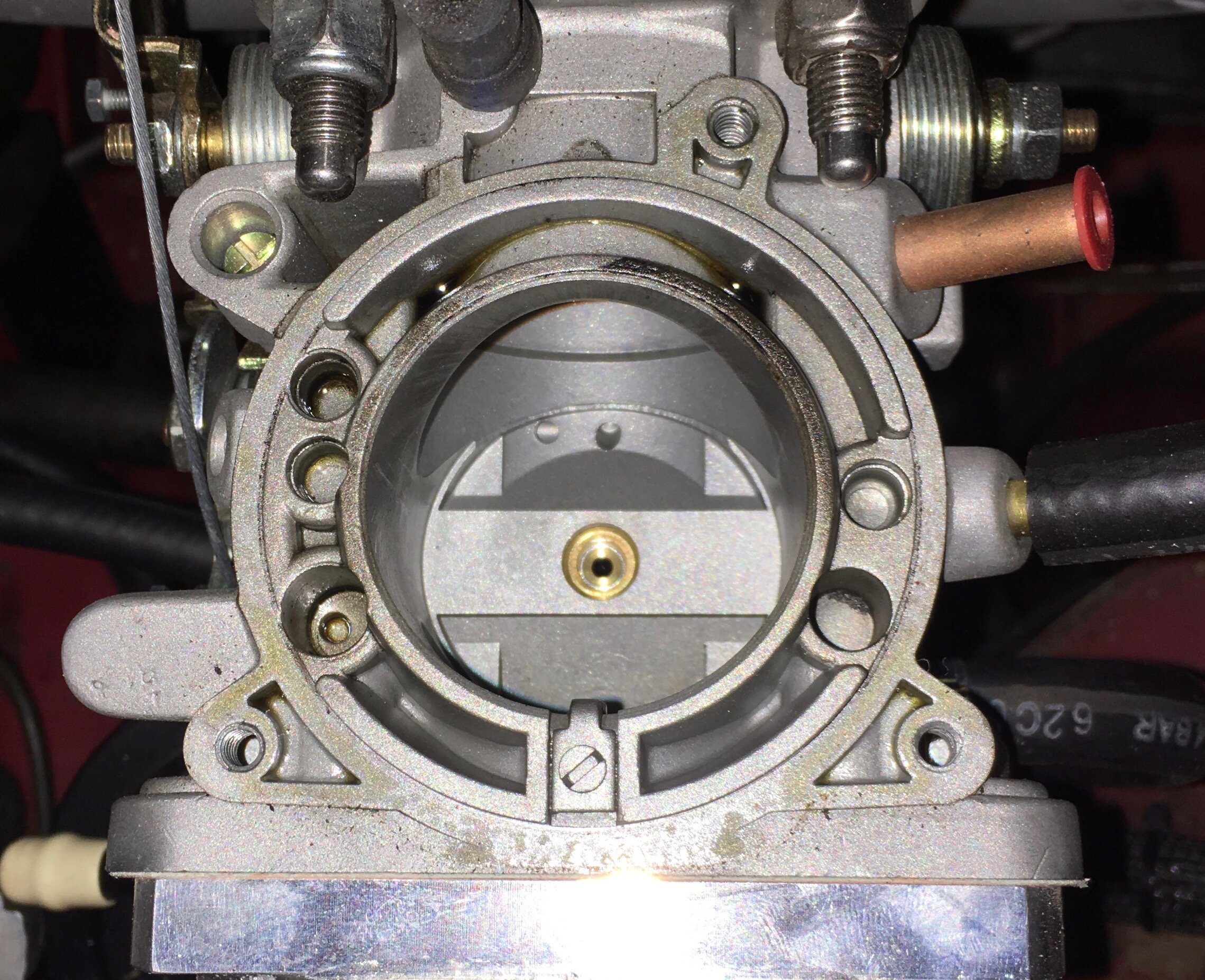
During our mixture testing and subsequent operation of the vehicle, we could not discern any difference with a sealed vacuum chamber mating surface. Therefore, the author’s carburetor is left ‘as is’ with no apparent ill effects.
However, if you want to seal yours, the solution is simple and effective.
For a temporary seal while fine-tuning mixture as discussed in the following section, you may cut a gasket using a fine-tip razor knife out of the thinnest, gasoline-resistant gasket material you can obtain (NAPA and other reputable auto parts stores stock various kinds, and numerous online sources exist).
Do this by simply placing the vacuum chamber on the gasket material, which should rest on a cutting board or other hard surface you do not mind scoring. Then tap the chamber sharply—but not so hard as to fracture the aluminum—with a non-marring hammer, or use a block of wood to avoid damaging the tower with the hammer. Finally, either use the chamber as a cutting guide or trace the shape with a sharp pencil, and cut out your gasket.
Once you have settled on the appropriate spring and needle combination for your engine and altitude range as described in the following steps, use anaerobic sealant to seal the vacuum chamber. The procedure for applying this sealant is described with photos in the rebuilding the supercharger section below.
Finally - the vacuum nipple atop the manifold flange in the MG Metro Turbo-spec HIF44 carburetor, indicated by the light blue or turquoise arrow in this image, is not absolutely necessary in our application:
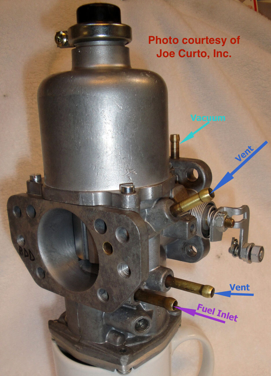
In the Metro Turbo-spec carburetor, that nipple is connected to the upper float chamber vent, as shown here:

The purpose of this connection is to offset the positive pressure referenced from the drilled passage into the plenum (or snorkel in our analogous application) at idle, under steady-state cruising, or under trailing throttle conditions. The net reduction in float chamber pressure effectively leans the air-fuel ratio (AFR) slightly to increase economy under those conditions.
Therefore, if you have a Metro Turbo-spec HIF44, you may either: (i) cap the nipple atop the manifold flange; or (ii) plumb it as usual per the above photo. In either case, plumb the vent hoses as discussed above for the standard-spec HIF44.
tuning the system
Once you have installed the high-pressure fuel system and modified the carburetor as described earlier in these instructions, there are just two aspects to tuning the system: adjusting the mixture and the timing.
STEP 1 - Install Cooler Spark Plugs & Adjust the Timing
You should run a cooler plug in a supercharged engine. Recommended plugs are in the parts list. Run a hotter plug at your own risk.
The timing procedure with this blow-through supercharger is essentially the same as usual—with one exception. You may wish to disconnect the vacuum advance tube from your distributor (if you have one) and plug its source before starting the engine under boost. This is because the chief function of the diaphragm is to introduce advance sooner—which may be unnecessary or even counterproductive under boost.
You may now set the timing as you ordinarily would, but while operating the car under load (uphill or accelerating briskly), listen carefully for pre-detonation or ‘pinging' and retard the timing only so much as required to eliminate it.
Once you have arrived at the optimum degree of advance, you may experiment with reconnecting the distributor diaphragm or leave it disconnected as we did.
*Note: we left our timing set to where it was before hooking up the supercharger, and experienced no discernible pre-detonation during mixture trials. We may experiment with introducing more advance at some point, and if so will post the results here.
STEP 2 - Determine the correct restrictor plate diameter
We have designed a ‘tunable’ blow-through HIF44 combination ram pipe, performance air cleaner and snorkel adapter. You must restrict the air flow at the mouth of the carburetor, as well as modifying the carburetor as discussed in an earlier section, or this blow-through system will not function.
Our adapter comes with three, interchangeable, profiled restrictor rings to allow you to select the pressure variable across the Venturi (or jet) best suited to your engine’s internal modifications, elevation, and selected boost:

The middle-thickness ring is 37mm, the same restriction built into the MG Metro Turbo’s cast plenum. This worked well on the author’s 1967 MG Midget test mule and should provide a good starting point for your mixture trials.
STEP 3 - Select an Appropriate Needle
*Note: altitude is the single most important factor when initially selecting a needle. You must pay close attention to your AFR gauge when testing needles to avoid burning an exhaust valve or potentially damaging an aluminum piston.
Based on our mixture trials—which were conducted between 5,000~6,000 ft. / 1,524~1,829 m.—we settled on the BCA or slightly leaner BDK needle (the MG Metro Turbo uses a BDD or the slightly leaner BFA needle; but both of these are significantly leaner than the BCA and were not viable in our case).
However, the owner of the blazingly fast white car in the video at the top of this page discovered that close to sea level a BCG needle, with an 8 oz spring and 90w/140 oil in the damper was needed to provide an adequately rich mixture.
The graph below compares the richness of some popular needles, with richness expressed as the 'Y' (vertical) axis, and the needle stations listed along the 'X' (horizontal) axis. We will update the graph with additional needles that may be good alternatives when time permits. An SU needle profile book with dozens of needle choices has been added to the online parts list.

Each needle station is measured at 1/8” from the shoulder of the needle—or the flat portion that is flush with the piston when installed as discussed in a moment—and the purpose of each station is listed along the top of this graph.
For easier viewing, you may download the current graph from the purchase page and expand it to ‘full screen’ mode, or simply click on the image on the item’s page and it will display larger:

Below is a photo series showing how to replace the spring-loaded needle.
The only things that may not be self-evident are: (i) one end of the spring is wound slightly differently and goes onto the new needle easier, with a gentle twisting motion; (ii) the set screw secures the jet guide by nestling into the slot machined into its side (don’t strip it out; seat it gently but firmly); and (iii) you must hold the jet guide flush with the bottom of the piston with your finger while tightening the set screw:
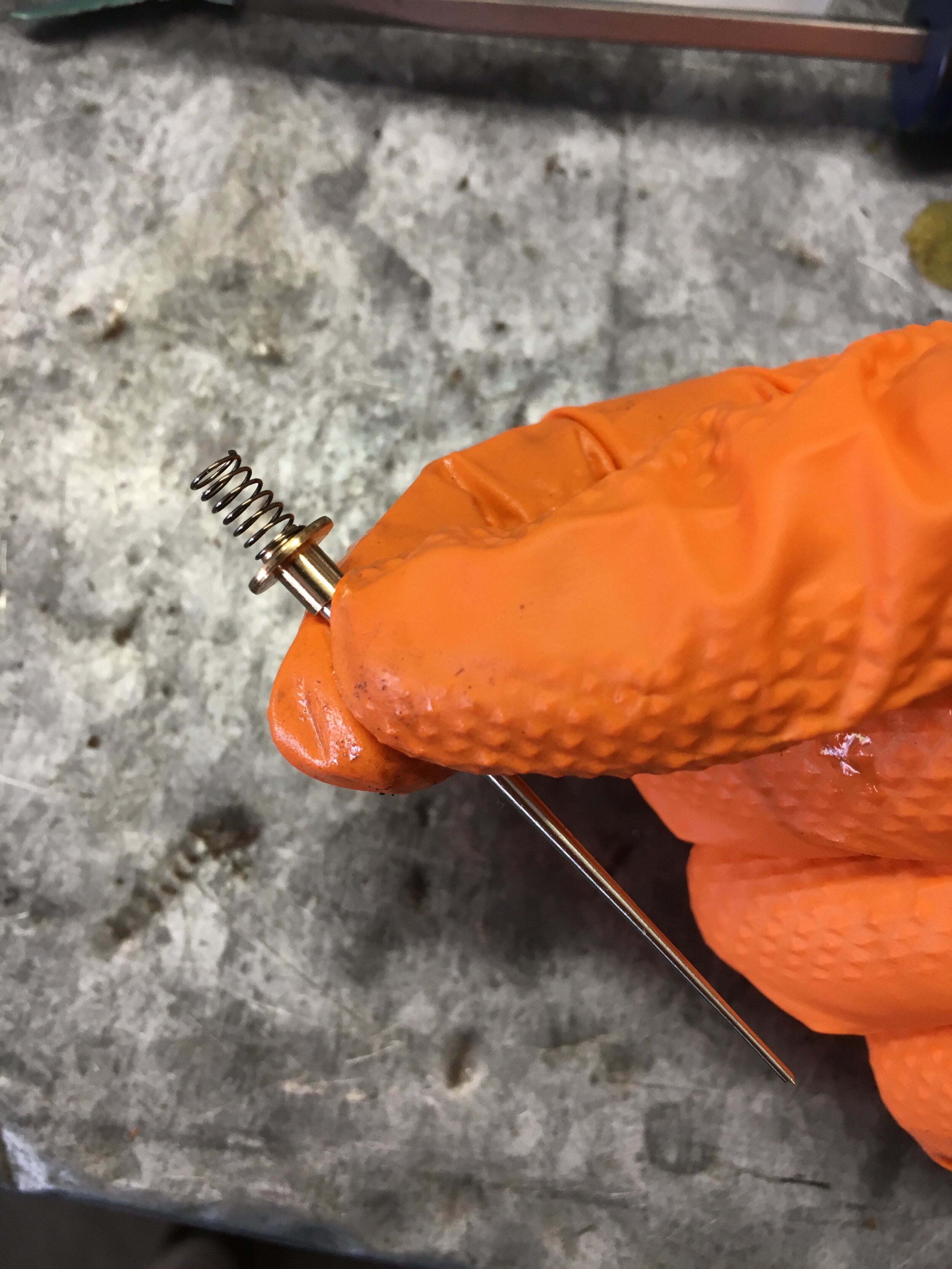
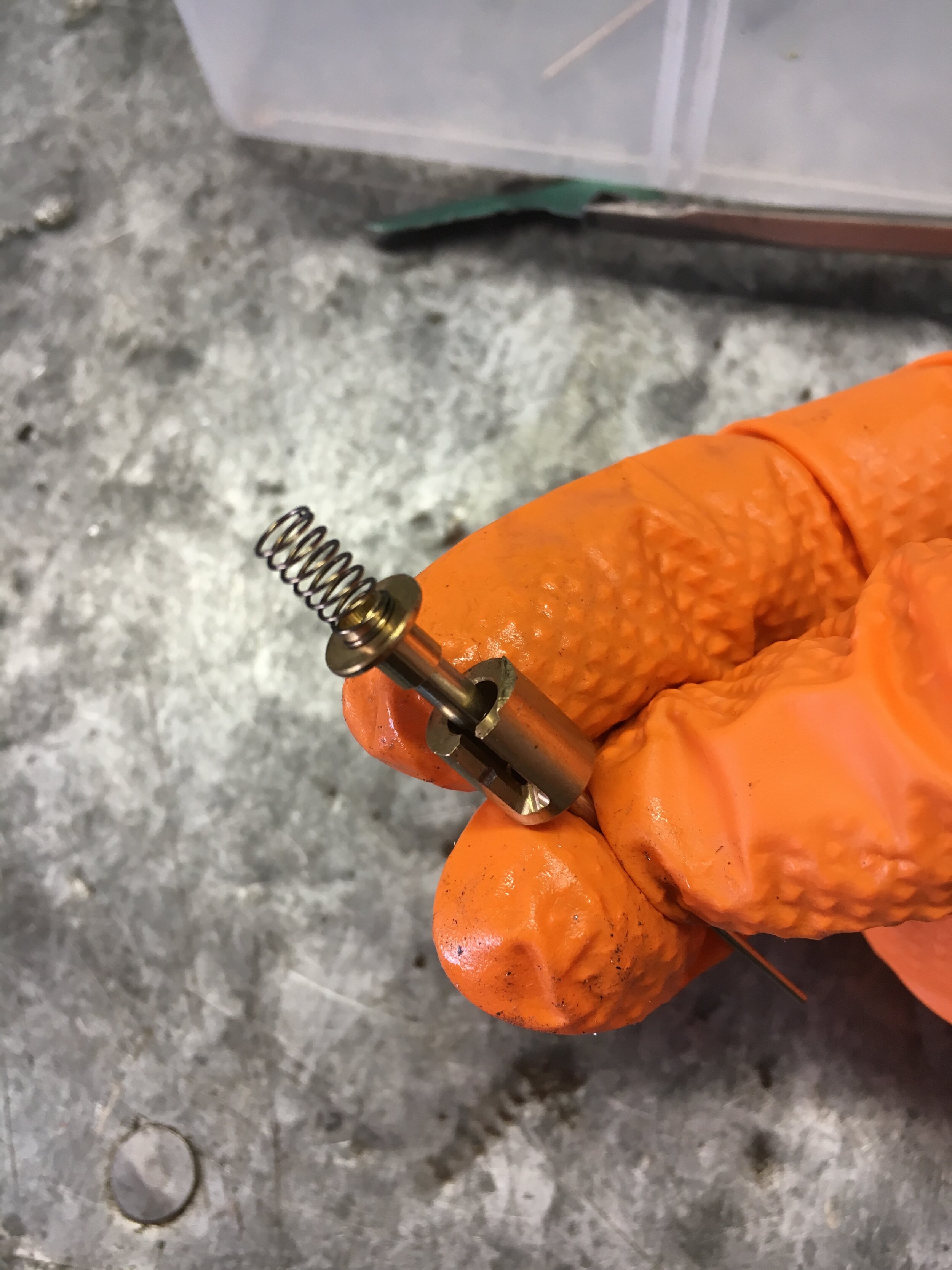
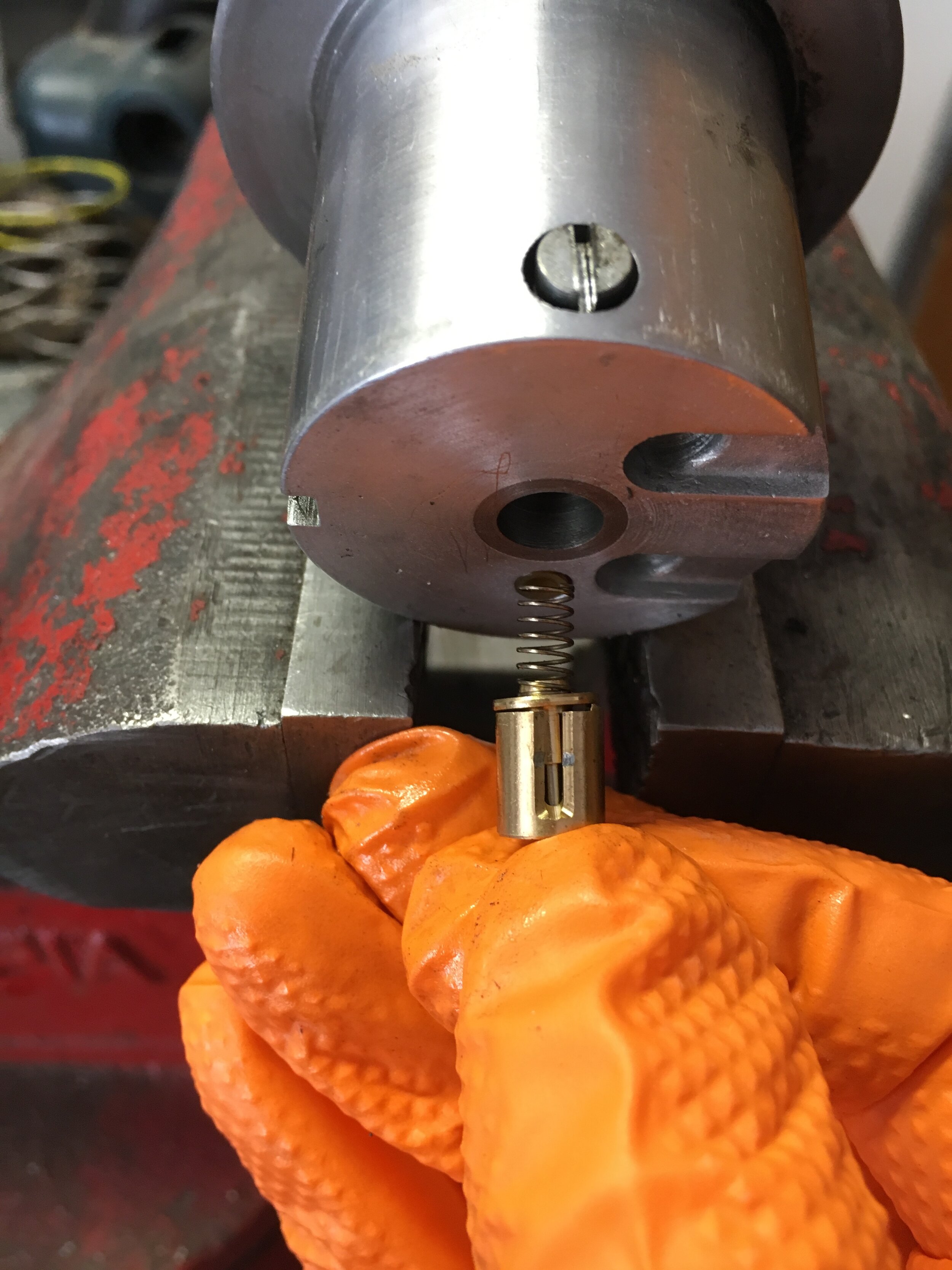
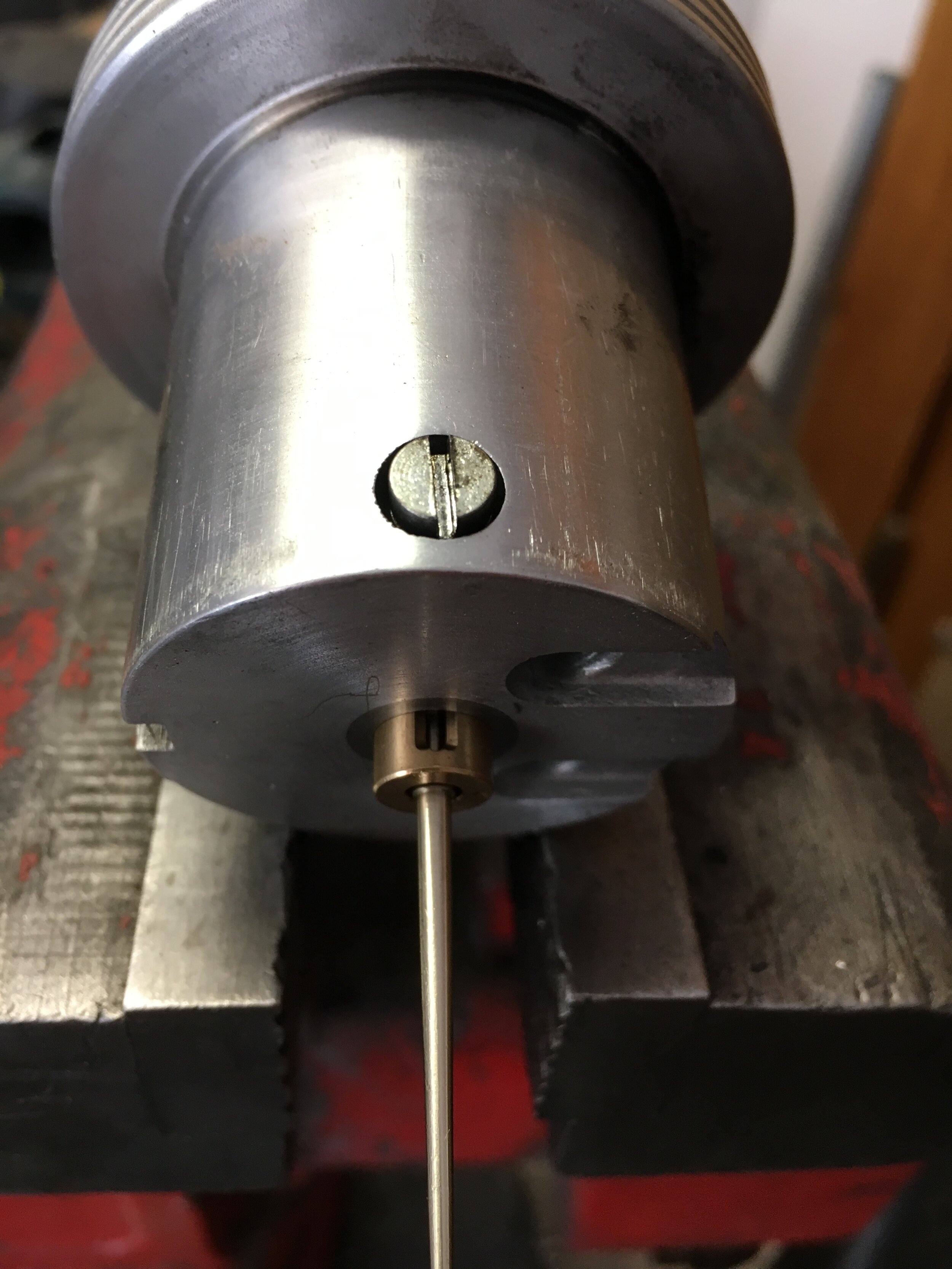
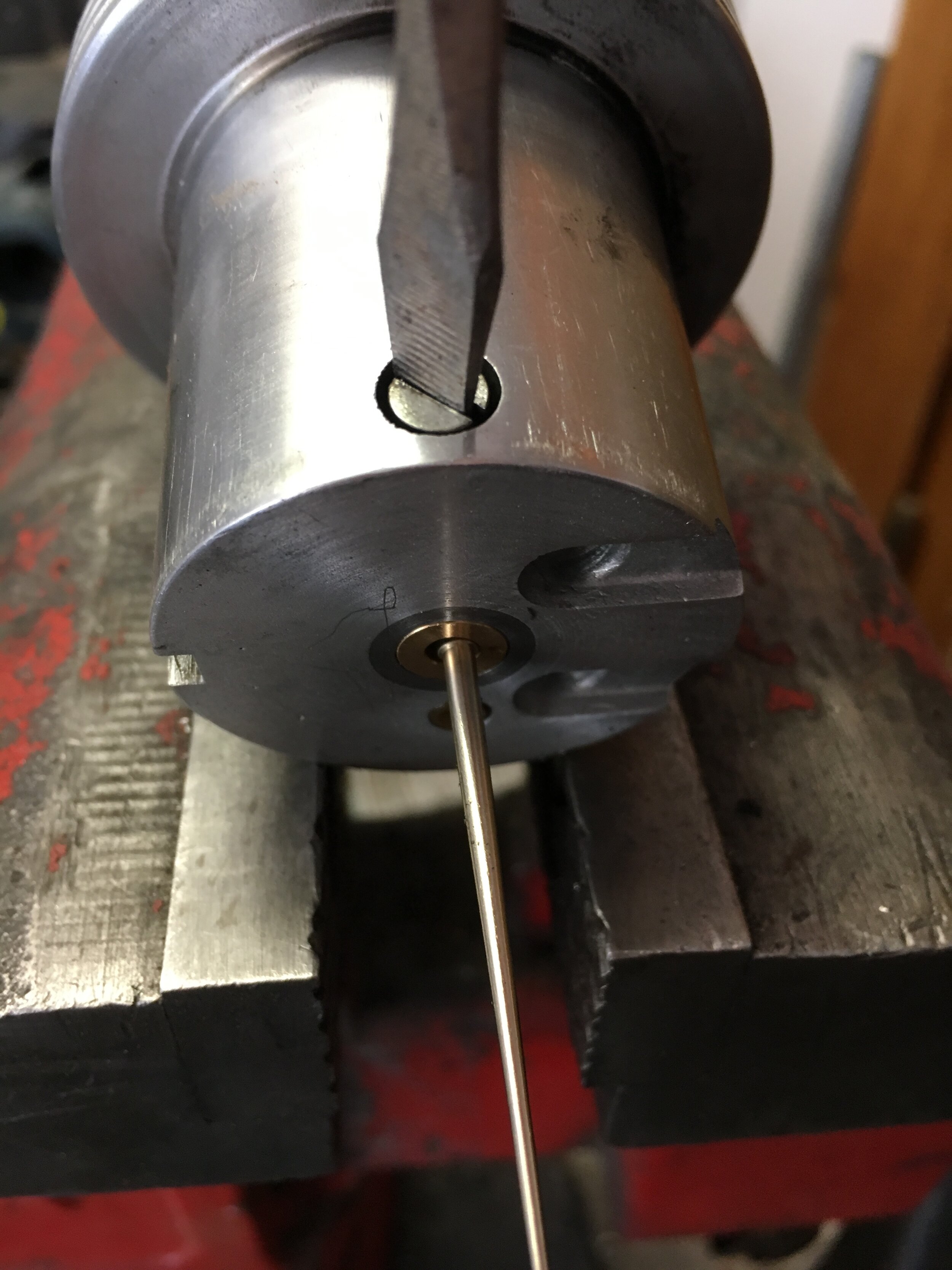
STEP 4 - Select a Spring
Here are the springs available for the HIF44, left to right: ‘Red’ or 4.5 ounces (the red paint on our spring faded); ‘yellow’ or 8 ounces; and ‘green’ or 12 ounces:

We found the 8 oz. spring worked best, but at lower elevations it is at least conceivable that you may need the 12 oz. spring, especially if running a smaller, high-boost pulley. On the other hand, if you are running a larger supercharger pulley for modest boost, you may find the 4 oz. spring adequate.
Changing the spring is simple, as there is no top or bottom to worry about:
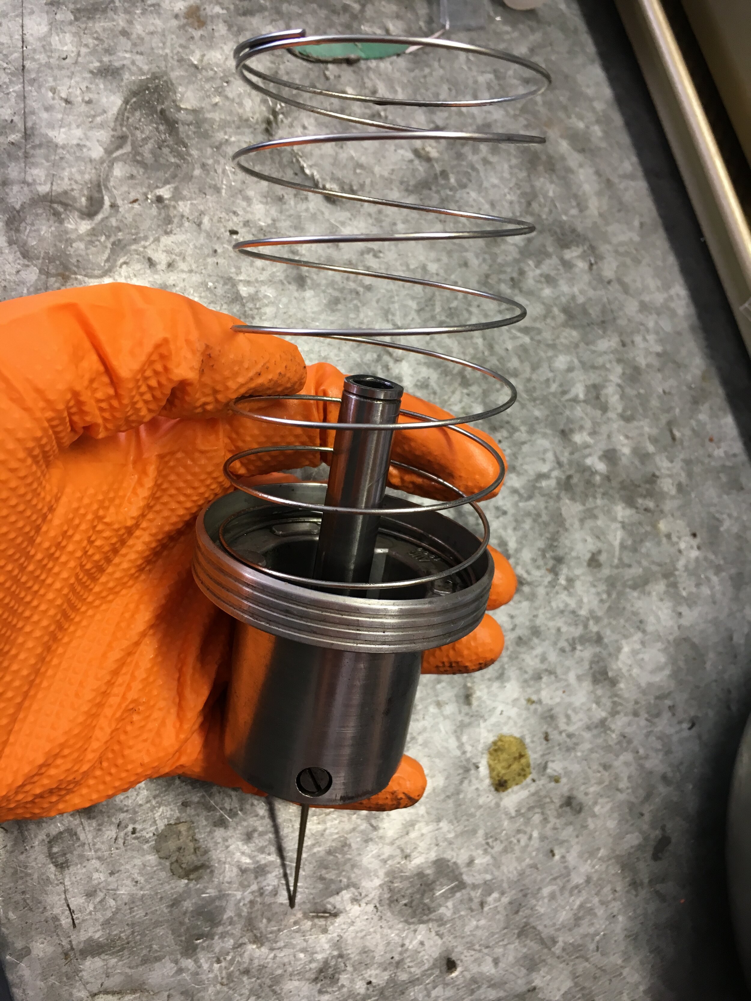
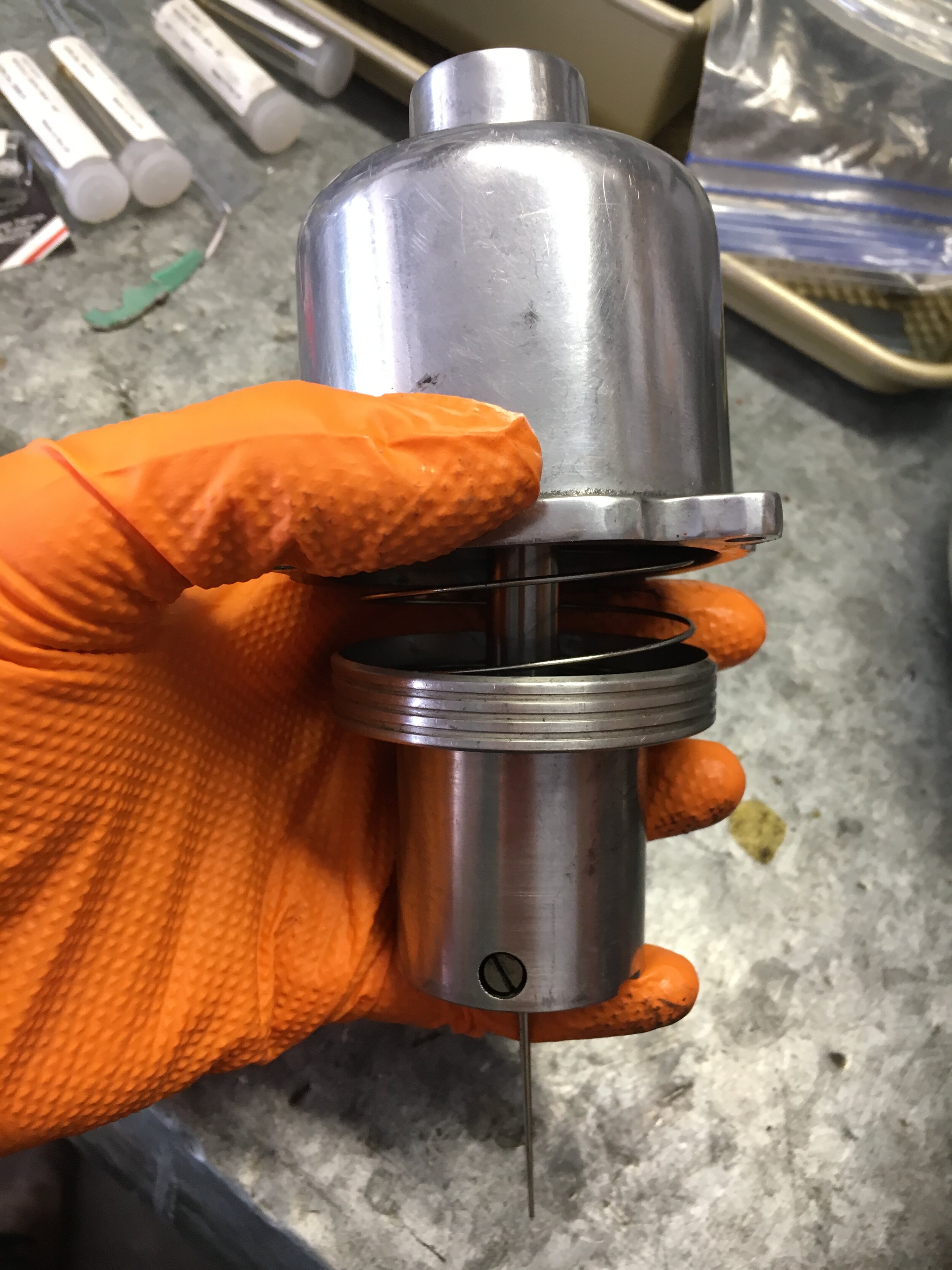
STEP 5 - Select an Appropriate Dashpot Oil
Again, our mixture trials were conducted between 5,000~6,000 ft. / 1,524~1,829 m. If operating at a lower elevation, you will probably need heavier oil in the dashpot to temporarily enrich the mixture during acceleration pulls and abrupt throttle position changes.
We recommend you have the following on hand for your mixture trials, and start with the lightest oil first, working your way up progressively:
Marvel Mystery Air Tool Oil (10W);
20W motorcycle fork oil;
20W/50 motor oil;
40W motor oil;
80W/90 gear oil.
STEP 6 - Adjust the Idle Mixture
It is important to arrive at the correct mixture for your operating conditions, though a supercharged engine is arguably less sensitive to moderate elevation changes than its naturally aspirated counterpart.
Accessing the Mixture Screw
One complication of positioning the bypass valve adjacent to the carburetor is that the mixture adjustment screw is difficult to access. One solution is a flexible extension and 3/16” flat blade screwdriver bit like this inexpensive set:
Hyper Tough 64-Piece Ratcheting Screwdriver Set - Walmart, $12.00
To save money and a trip to the store, the author inserted a screwdriver bit into a piece of 1/4” fuel/vapor hose, and made a serviceable tool. To use it, you reach into the gap just to the rear of the carburetor and turn the hose where it is stretched onto the bit, while holding the end of the hose to apply additional twisting force and keep the bit from falling out of the screw’s slot:

Once you have selected your initial needle, spring, and oil combination, start the engine as usual and warm it up, and then turn the mixture adjustment screw to achieve an average AFR reading of 13:1. You may set the idle slightly richer or leaner as necessary to obtain a smooth idle.
Blip the throttle between adjustments and let the idle settle down each time to take a reading, which will vary up and down slightly—which is normal.
*Note: you may have to readjust the idle speed after changing the mixture.
STEP 7 - Conduct Mixture Trials
You may now drive the car, paying close attention to your AFR gauge and engine temperature—which should not exceed the normal operating range at any time.
You may wish to consider our DIY VW Rabbit (Golf) dual-pass crossflow radiator conversion.
Do not worry about backfiring or rough running during warmup: those are symptoms of a draw-through setup that must heat the supercharger rotor housing by conduction before operating properly, and which lacks an intercooler and dynamic bypass valve circuit. Your car will operate smoothly and retain all of its accustomed drivability, irrespective of operating temperature.
Your goal is to approximate the following AFR readings, but you should avoid running leaner, to avoid damaging the exhaust valves or pistons:
Idle - 13:1 (not critical)
Light throttle - 14.5:1 ~ 14.7:1 (stoichiometric is 14.7:1)
Heavy throttle/Boost - 11.8:1 ~ 12.5:1
Cruising (level ground) - 15:1 ~ 16:1 (you may not be able to achieve a cruising AFR this lean with an off-the-shelf BCA needle, and without utilizing the ‘lean out’ hose discussed in the previous section)
We will soon be experimenting with four of the seven smaller ‘high-boost’ pulleys available for the Smoothflow M45 modular pulley system used in this conversion, and will post the related data as well. The wide range of pulleys allows you to dial-in performance as mild or wild as you wish:

The below image shows what you get for $18 less than the Moss Motors ‘high boost kit,’ which consists of one smaller pulley, an adjuster bracket, and hardware. You get three progressively smaller ‘high boost’ pulleys from Smoothflow, a second idler and bushing in the parts list, and a fastener from your hardware store:

compare your results
We have tested needle/spring/oil combinations and HIF44 restricter ring selections. We have provided Air/Fuel Ratio (AFR) and other data gathered from the internally stock 1275cc test mule in the table below. (“TBA” indicates the data in that column is “to be announced.”)
If you wish, you are welcome to submit videos of track trials, acceleration tests, etc., and/or a slide show of your project, on the ‘customer cars’ page linked here.
test vehicle # 1 - 1967 MG Midget:
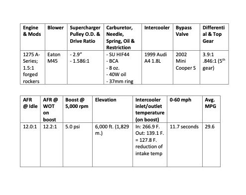
The standing start 0-60 mph acceleration test should be conducted without dumping the clutch to avoid any significant traction variable.
The average fuel economy test should ideally include a mix of city and highway driving, with the overall distance logged provided. The above table shows that the test mule averaged 29.6 mpg traveling 90 miles over a mix of city streets (30-45 mph), two-lane blacktop (50 mph), and interstate (75 mph).
Select and harvest a used supercharger
The M45 (45 C.I.D) Eaton roots-style blower, model no. 207018 or 206127 (which are essentially identical), sourced from either a 1999 to 2003 Mercedes Benz SLK230 Kompressor coupe or from certain 1999-2000 Mercedes Benz C230 models—but in either case, without an electronic clutch.
This supercharger can be had from self-service chains such as U-Pull-&-Pay and similar business for as little as $67 (which may not include core and environmental charges). However, the cast manifold and plastic air box to which it is attached are typically extra, and extracting the supercharger from the bowels of the Mercedes donor car takes about an hour.
Here is a video showing how to remove the blower with a handful of ordinary tools—but disregard the method of changing the gearbox oil, which is silly in light of the drain plug on the face of the unit:
Another money-saving alternative is to buy a supercharger from a recycling yard that has already removed it from the vehicle. Prices vary, but expect to pay five to six times as much—and often you will get the manifold and air box, with mass air sensor attached, as depicted in the next image.
Note: if you go this route, make sure to select a listing that allows returns and does not have a restocking fee, as it is common for blurry pictures to hide scoring to the rotors, and of course one cannot smell the synthetic gearbox oil leaking into the rotor chamber. Those seals are not easily replaced and that requires re-timing the rotors.

Either way, try to confirm the mileage of the vehicle. The blower pictured above was the ideal situation: a 2000 Mercedes SLK 230 that had been totaled with just 10,000 miles on the clock.
If you are fortunate enough to find a low-mileage blower, all you need do is unbolt it from the manifold and air box (which can be sold to recover some of your investment), remove the OEM steel pulley, install the SmoothFlow modular pulley system linked from our 5-rib crankshaft pulley’s purchase page, and change the synthetic oil in the gear box.
In any case, be sure to cut or remove the drive belt on the donor vehicle and rotate the pulley, listening carefully for grinding or metal-to-metal contact. This is not necessarily a deal-breaker, as the snout’s bearings and seals are easily replaced as discussed elsewhere in these instructions.
If you are unsure whether the rotor chamber has been gouged due to extended service of the bearings or abuse by the donor car’s owner, and you are looking at a potentially viable $56 blower, it may be worth your while to remove the unit to peer into the rotor chamber and inspect for damage.
Light scuffing on the tips of the rotor lobes and around the circumference of the chamber are not a concern, as the boost level needed to multiply the performance of the A-series engine is very modest; deep scratches into the casting and visible wear on the tips of the lobe disqualify the unit.
Here are pictures of a good unit (left) and a unit that is questionable (right):
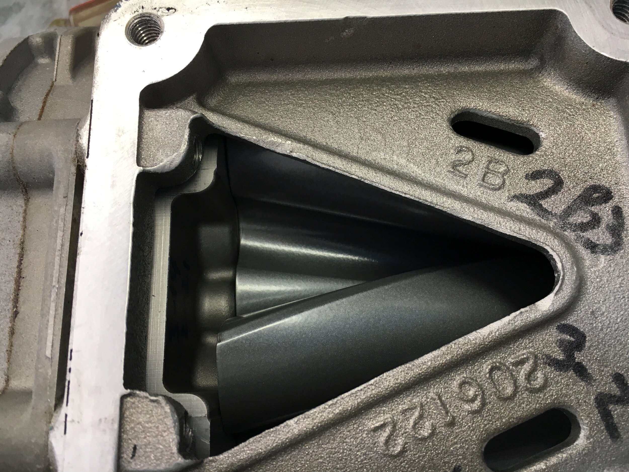
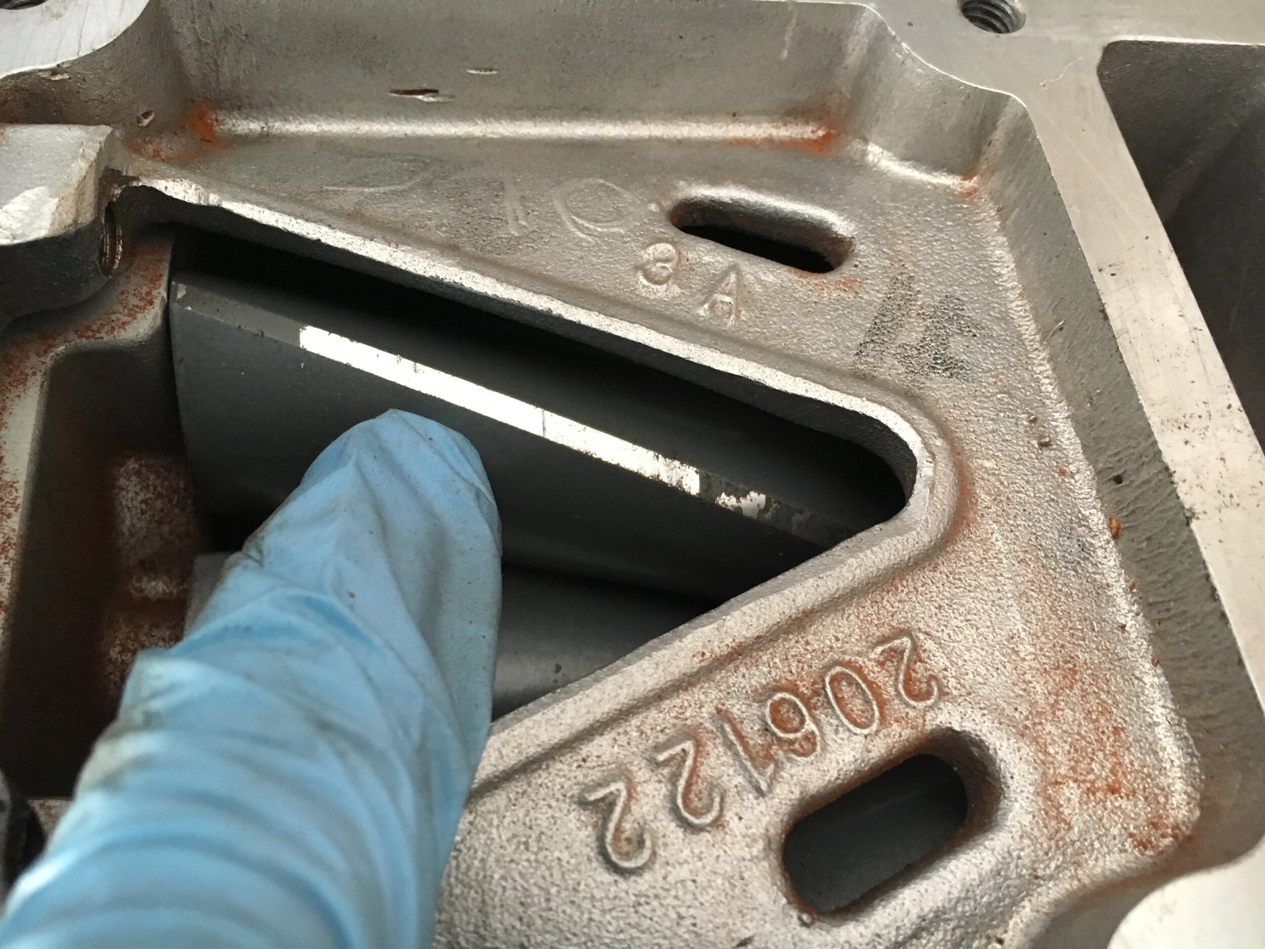
If the wear or scuffing is light, the unit is viable—but if the ‘pocket’-style needle bearings pressed into the rear of the rotor housing are going (likely if the car has well over 100,000 miles), they can be difficult to extract. We are developing a special tool to extract the bearings for a nominal charge, but until that service is available, try to locate a blower that, if anything, just needs a snout rebuild—which is well within the skills of the typical ‘shade tree’ MG mechanic.
Finally, if the rotors are coated with smelly fluid, it is likely that the seals between the gear box and rotor chamber have gone. That, too, will require a rebuild that involves timing the rotors—for which you need another special tool.
rebuild a used supercharger
If you are fortunate enough to find a low-mileage used supercharger, or wealthy enough to buy a new one, all you need to do is replace the pulley as described above. However, many people will obtain a used supercharger that needs either a front seal or snout bearings, or both. Occasionally, a supercharger will need the ‘pocket’-style needle bearings pressed into the rear of the housing.
This section covers the first two possibilities; we have designed a tool to remove the rear needle bearings, should they become frozen and impossible to remove with a standard slide hammer-style removal tool. We hope to add a related section in the future.
STEP 1 - Removing and Replacing the Snout Housing
This step involves a complication—separating the snout from the gear case housing without disturbing the anaerobic sealant sealing the gear case housing to the rotor chamber. That complication is readily overcome with a simple flat pry bar you can fabricate from 3/16” or even 1/8” mild steel bar, as shown in the following photo series.
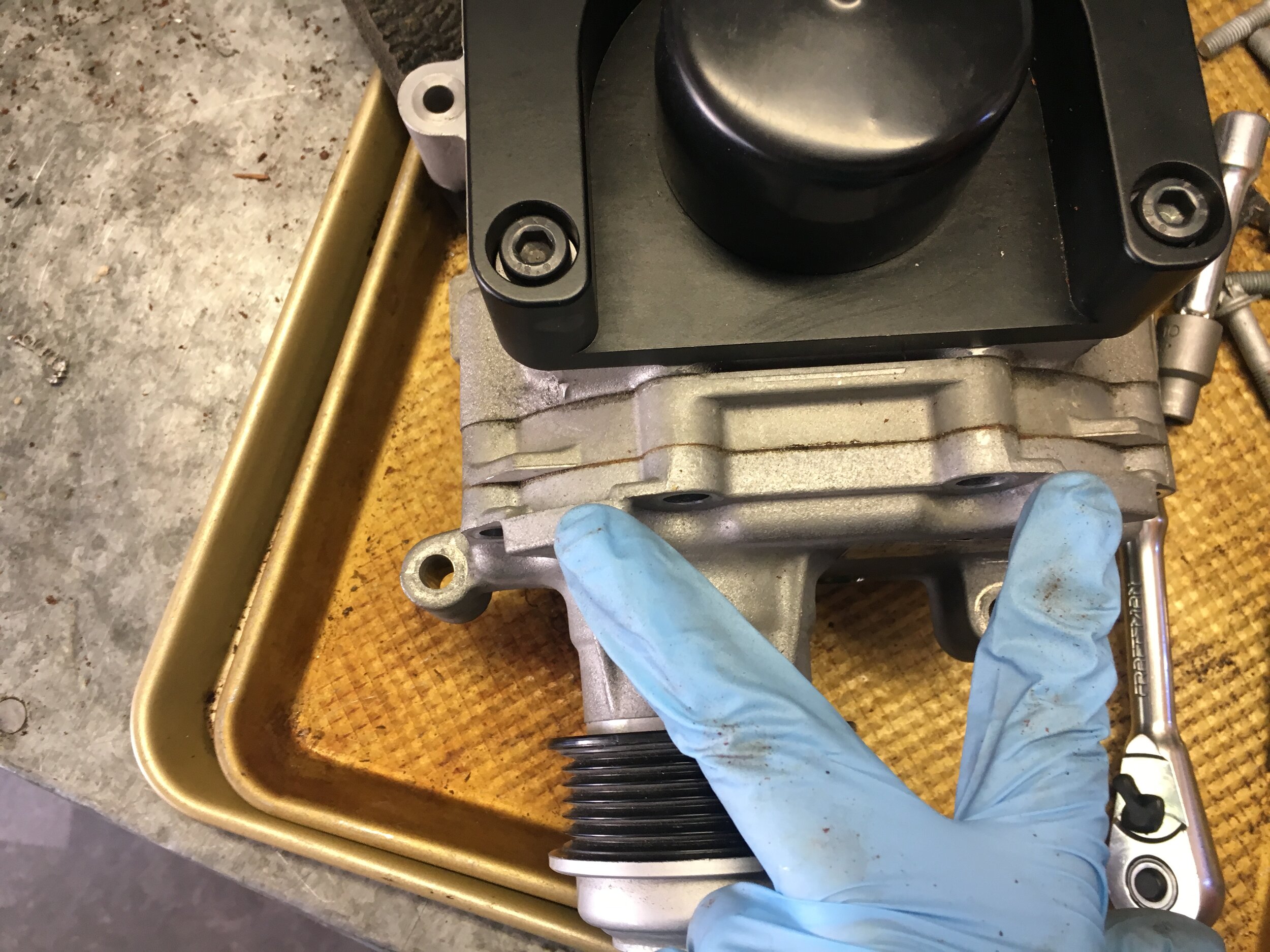
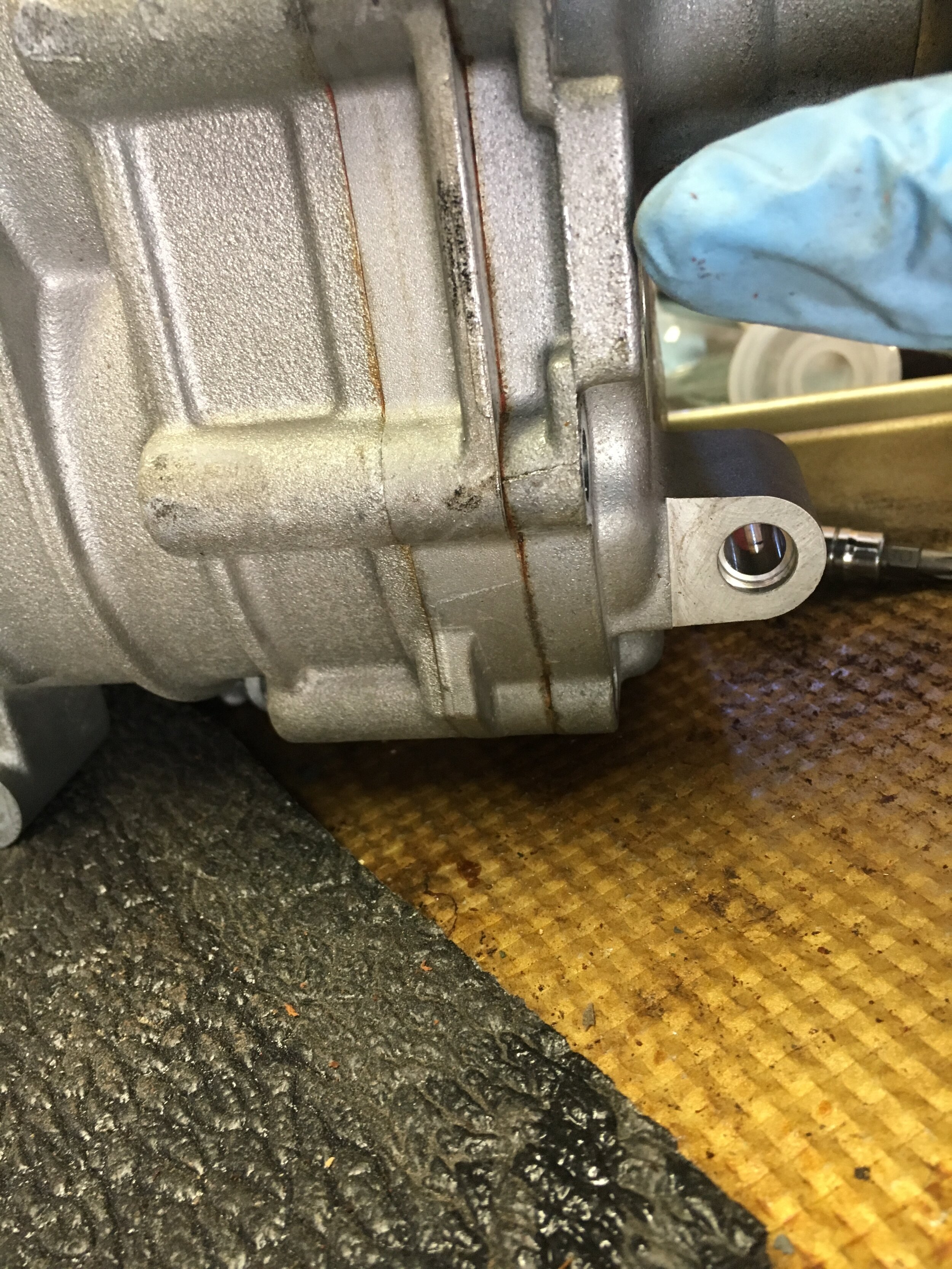
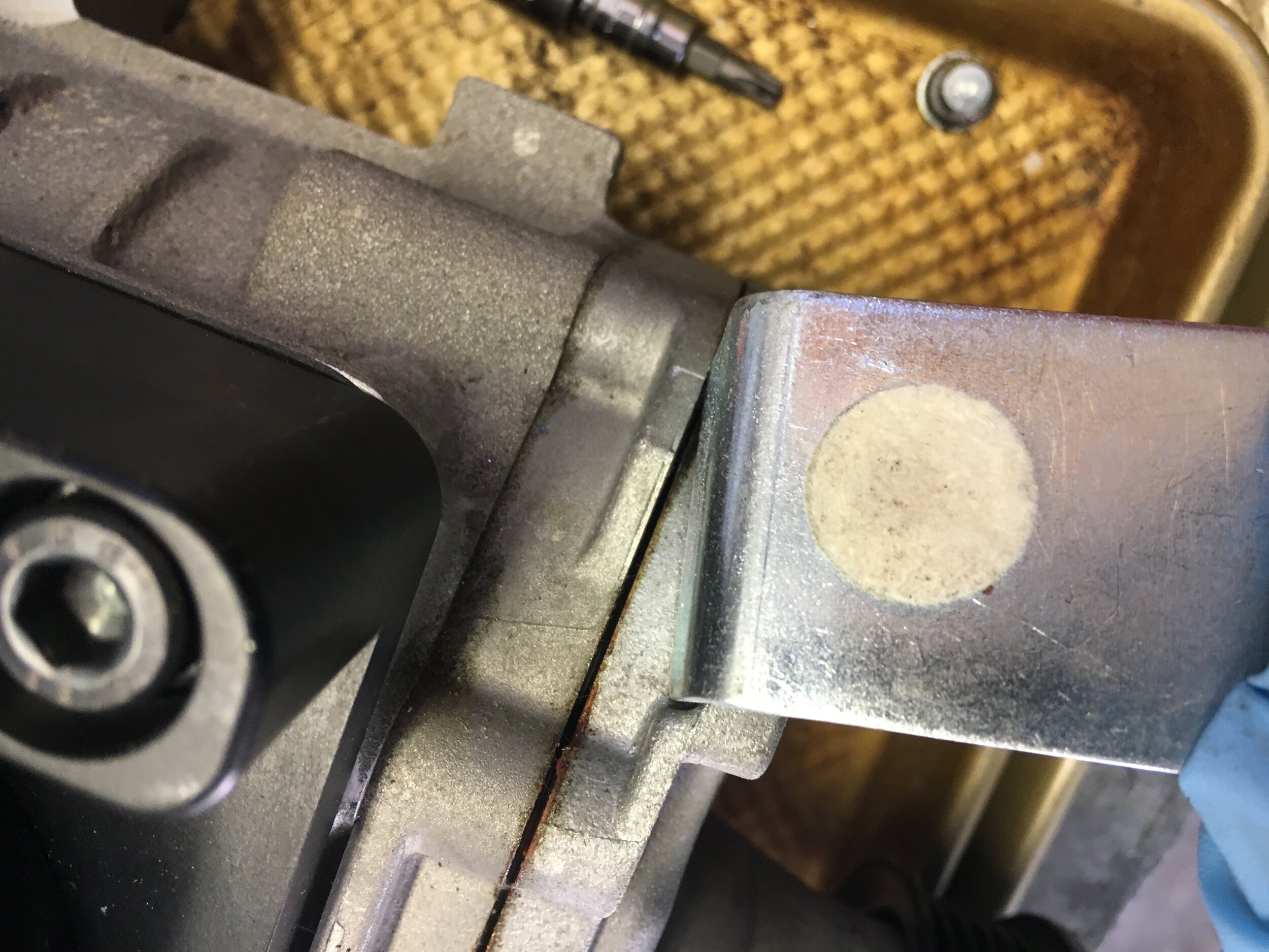
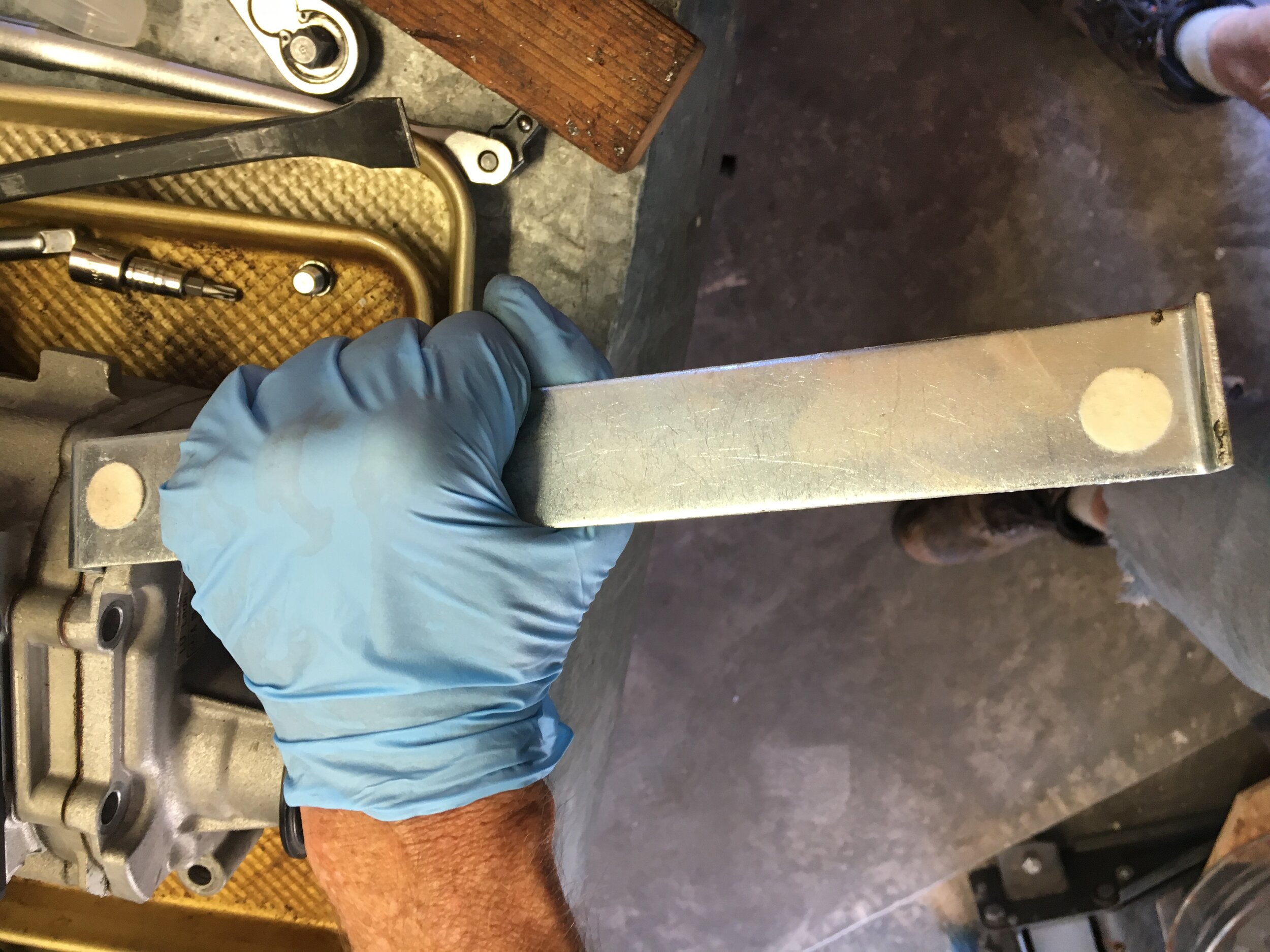
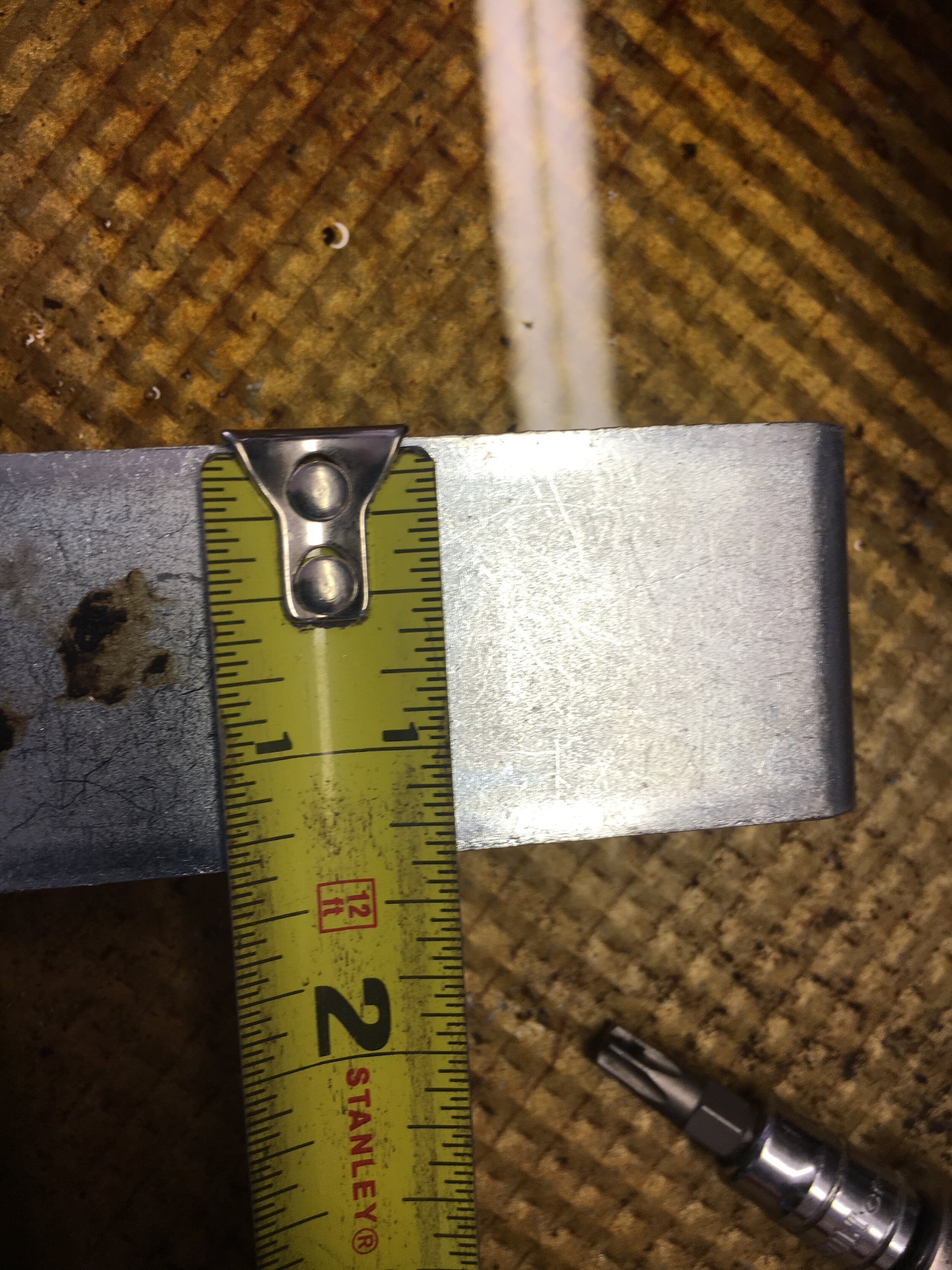
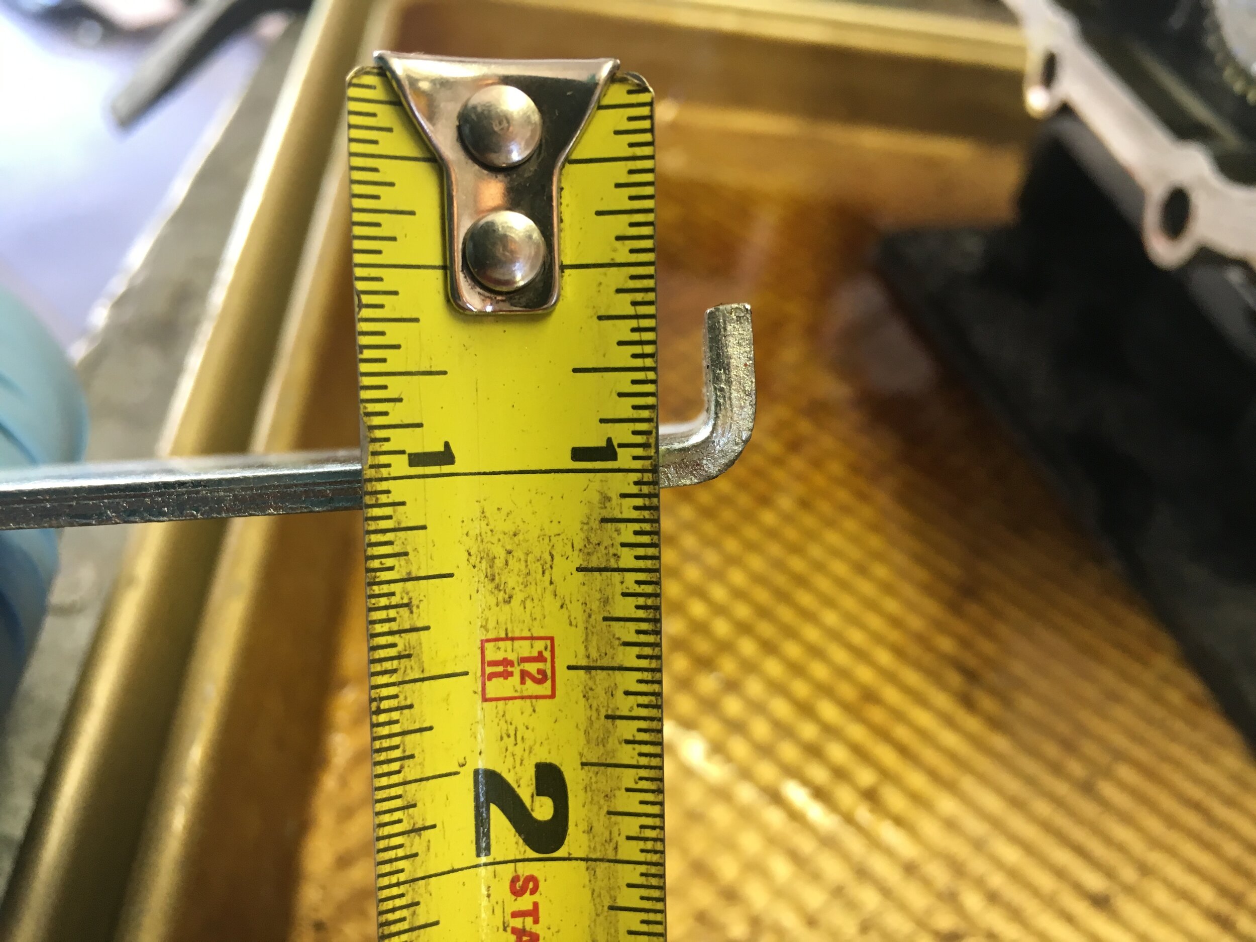
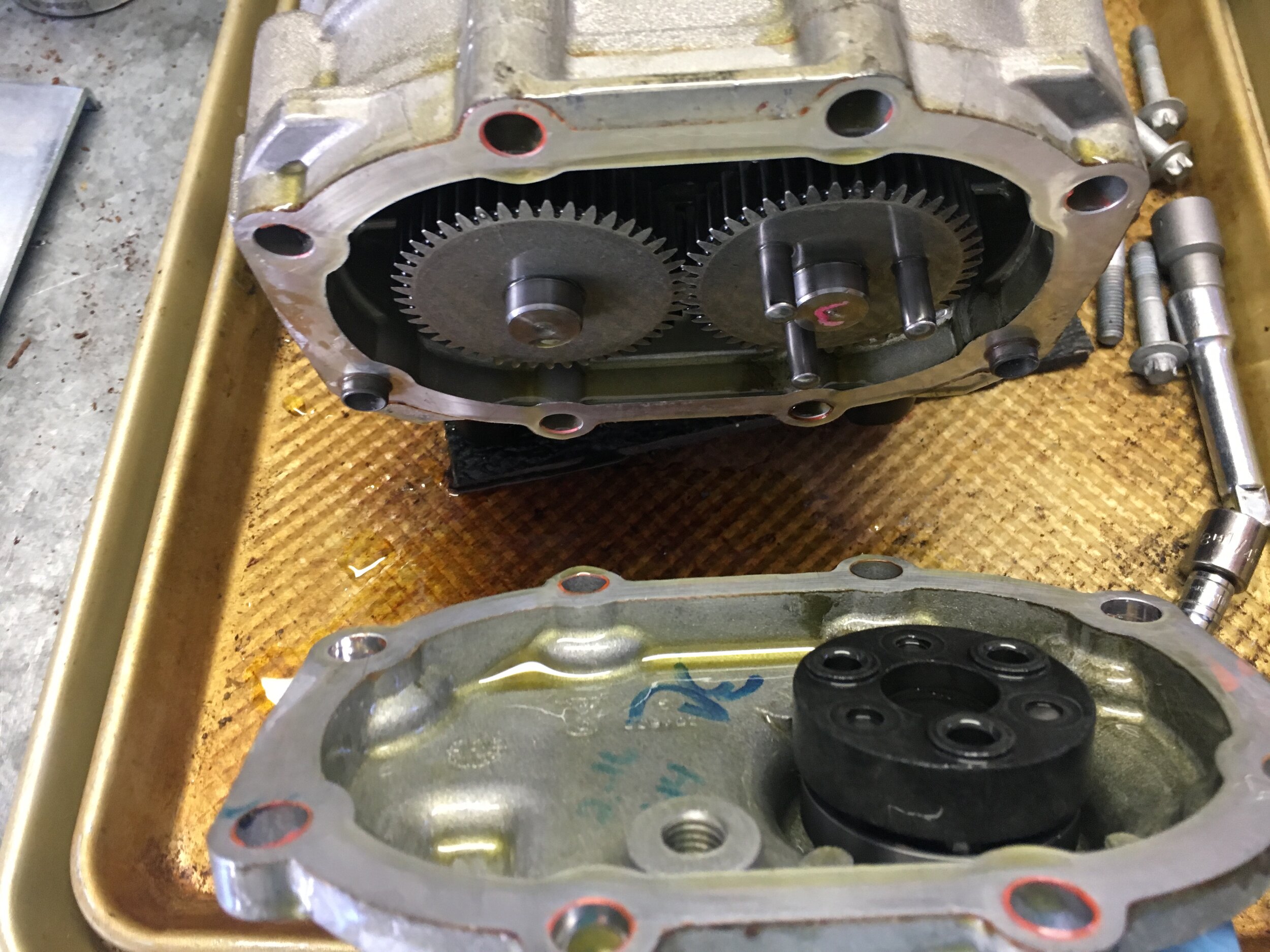
Note in the last photo the black plastic coupler that transfers rotational force from the pulley to the driven gear. After you have separated the snout from the gear housing a little ways, the coupler will cling to the pegs. DO NOT apply a pry bar or screwdriver to the mating surfaces, or the aluminum may become gouged—a condition that the anaerobic sealant is not designed to rectify.
If you are merely replacing the coupler or wish to use an arbor press to install the Smoothflow modular pulley hub, all that is left is cleaning the mating surfaces to remove the leftover sealant. You may use gentle pressure with #0000 steel wool and Goof Off or your favorite solvent to produce serviceable mating surfaces like these:
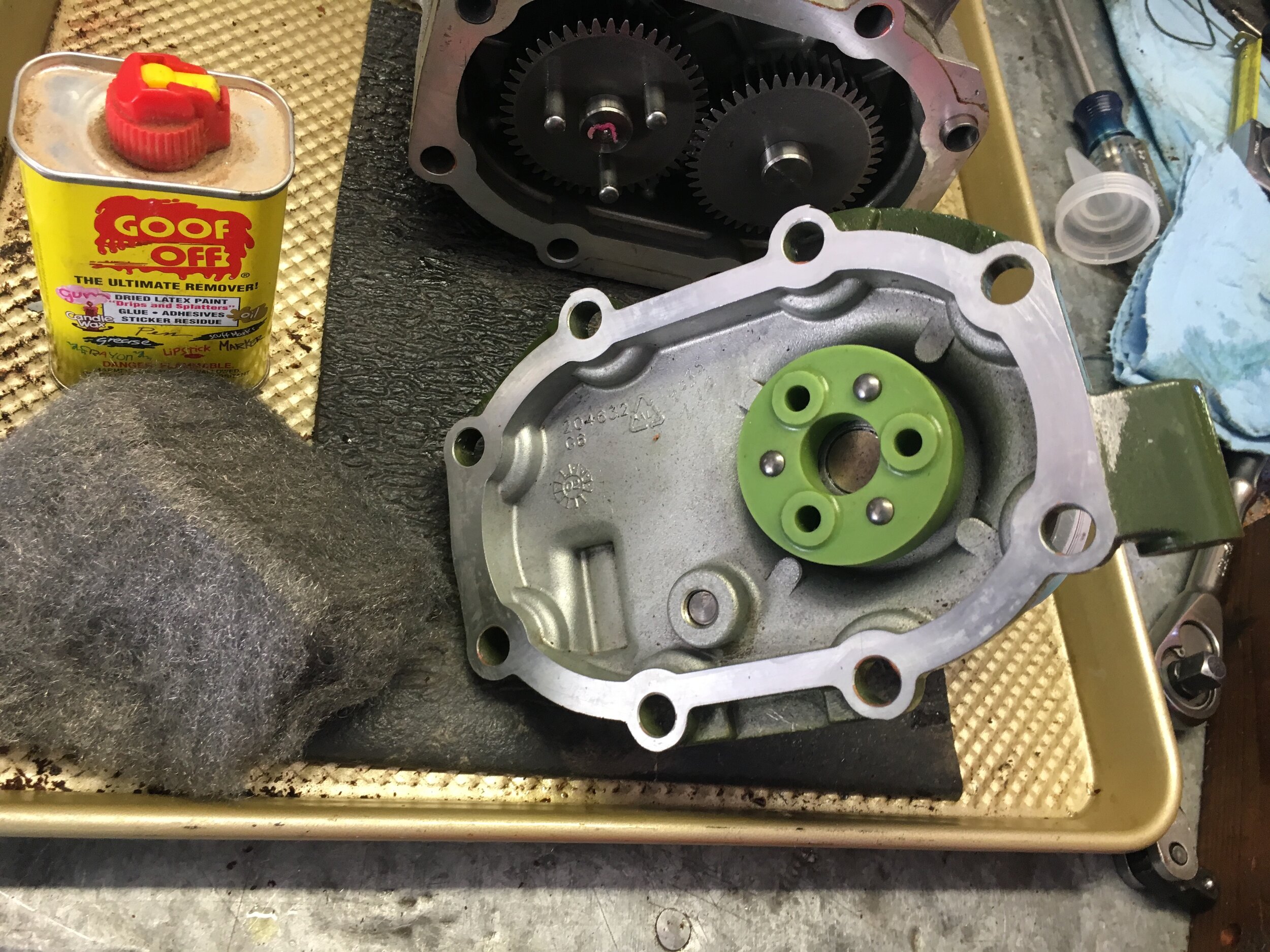
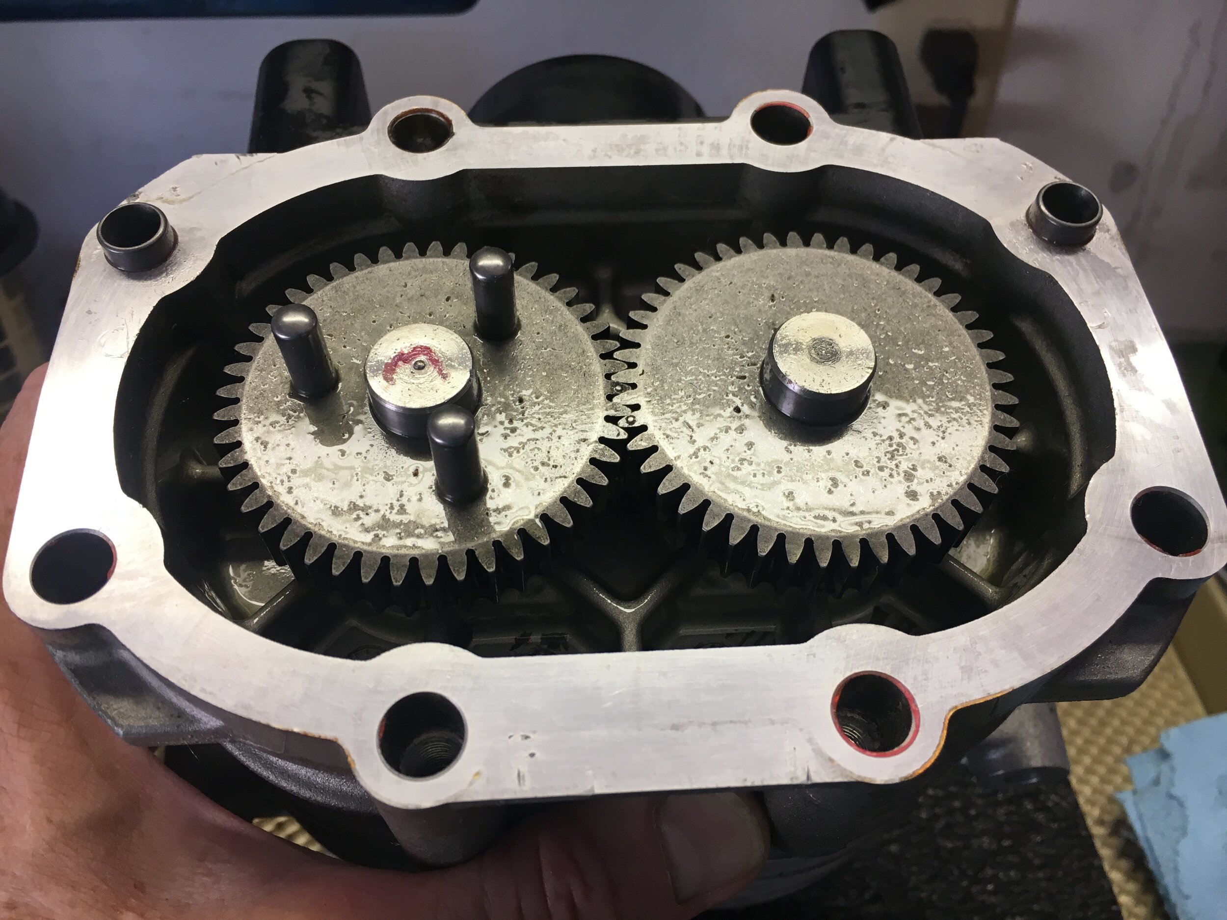
The green coupler in the first above photo is an upgraded type available on the internet. You may wrestle the old coupler off with your hands, but it is also safe to use a flat blade screwdriver to pry it off so long as you do not apply force to the mating surface. Use a block of wood or small angled pry bar, such that leverage is not applied to the mating surface.
Use the correct Permatex anaerobic sealant for aluminum flanges pictured below (they make more than one kind), and make sure to follow the directions on the back closely—such as using their special surface preparation on one side of the joint only:

Here is a photo series showing how to prepare the surfaces for resealing—and a handy way of holding the rotor chamber during the operation.
Note that you should (i) carefully insert the drive gear’s pins into the plastic coupler; (ii) start the screws a few turns; and only then (iii) firmly but carefully tap the pins fully into the coupler with a plastic dead-blow hammer or rubber mallet, before torquing the screws as you would a cylinder head—in a cross-hatched pattern, and remembering that you are working with an aluminum casting (so do not strip the threads):
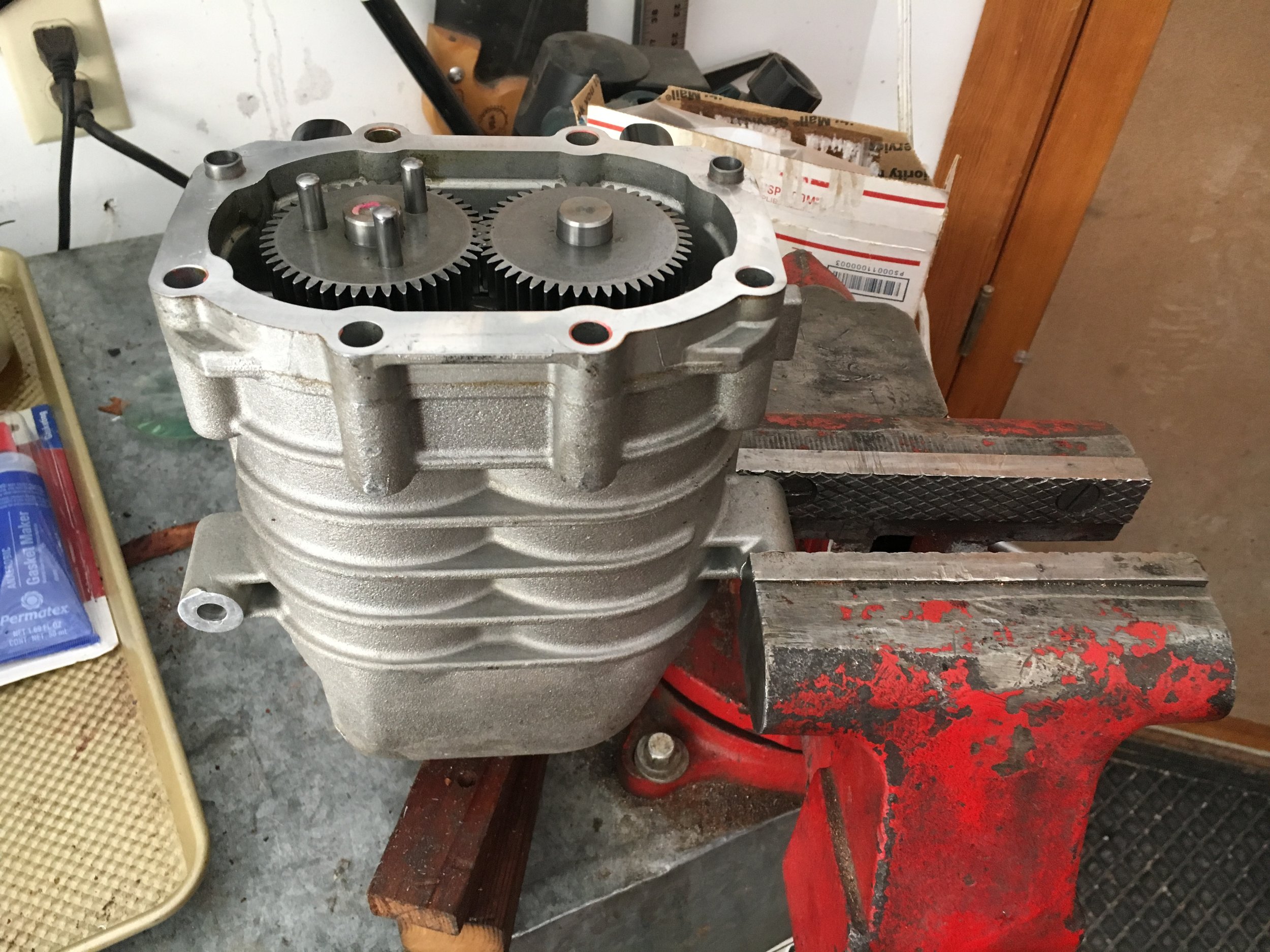
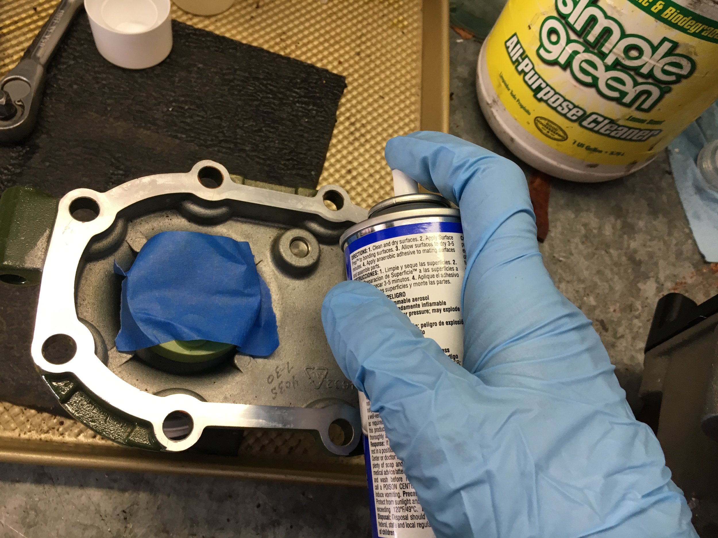
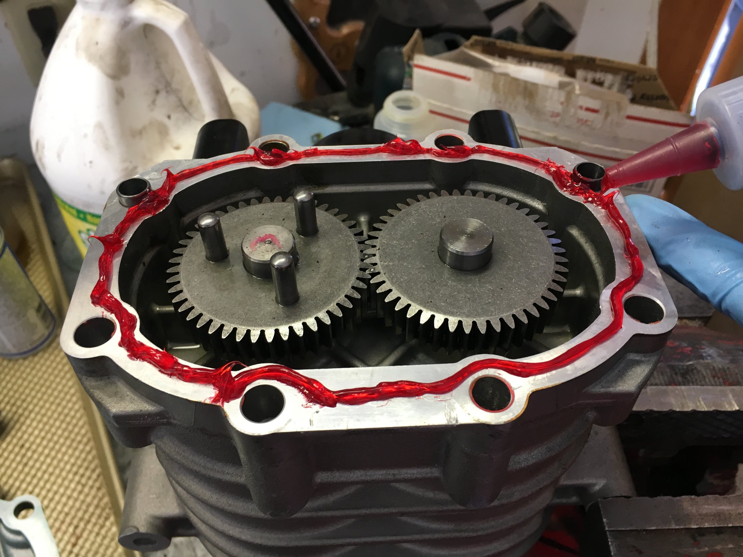
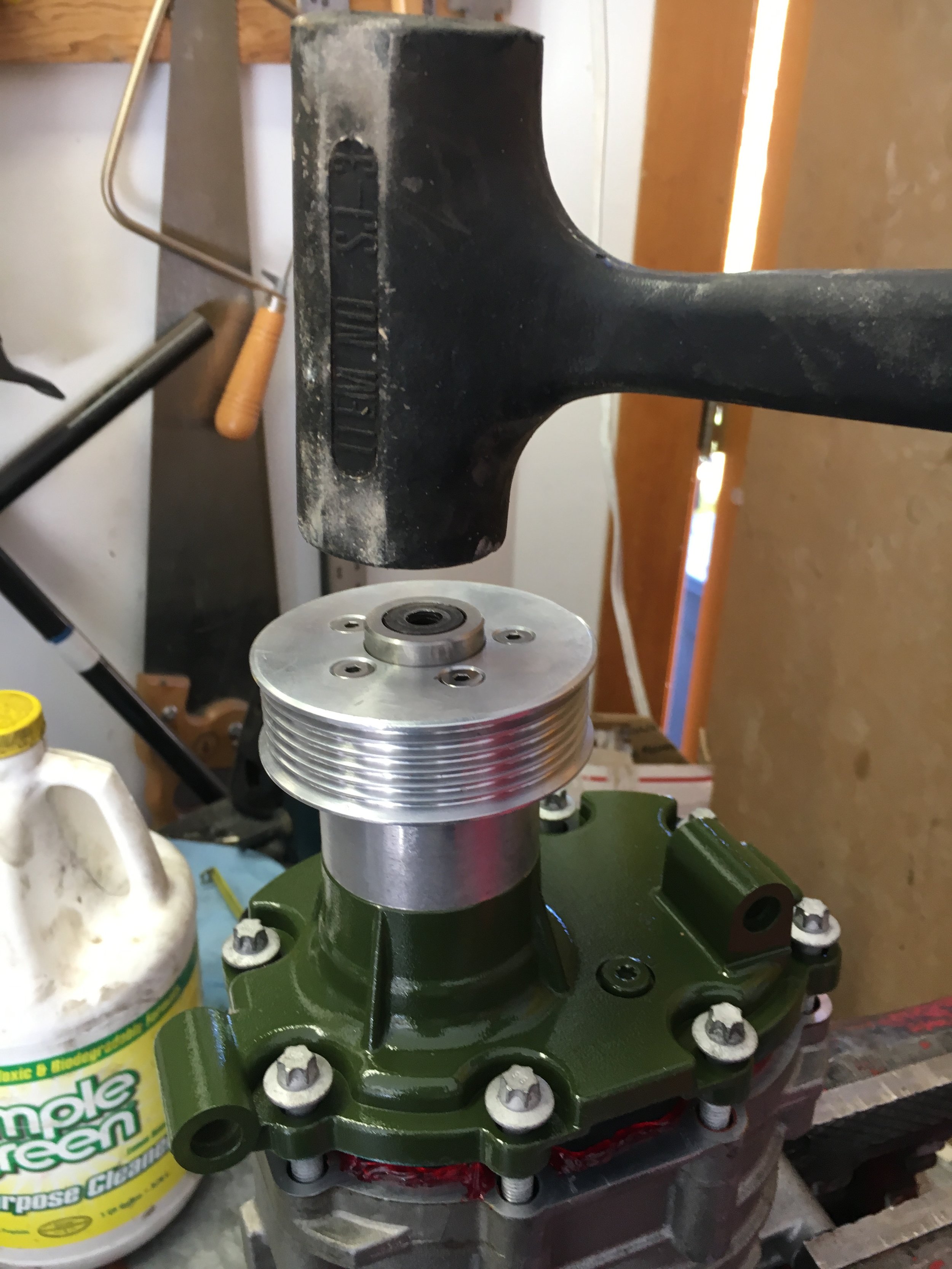
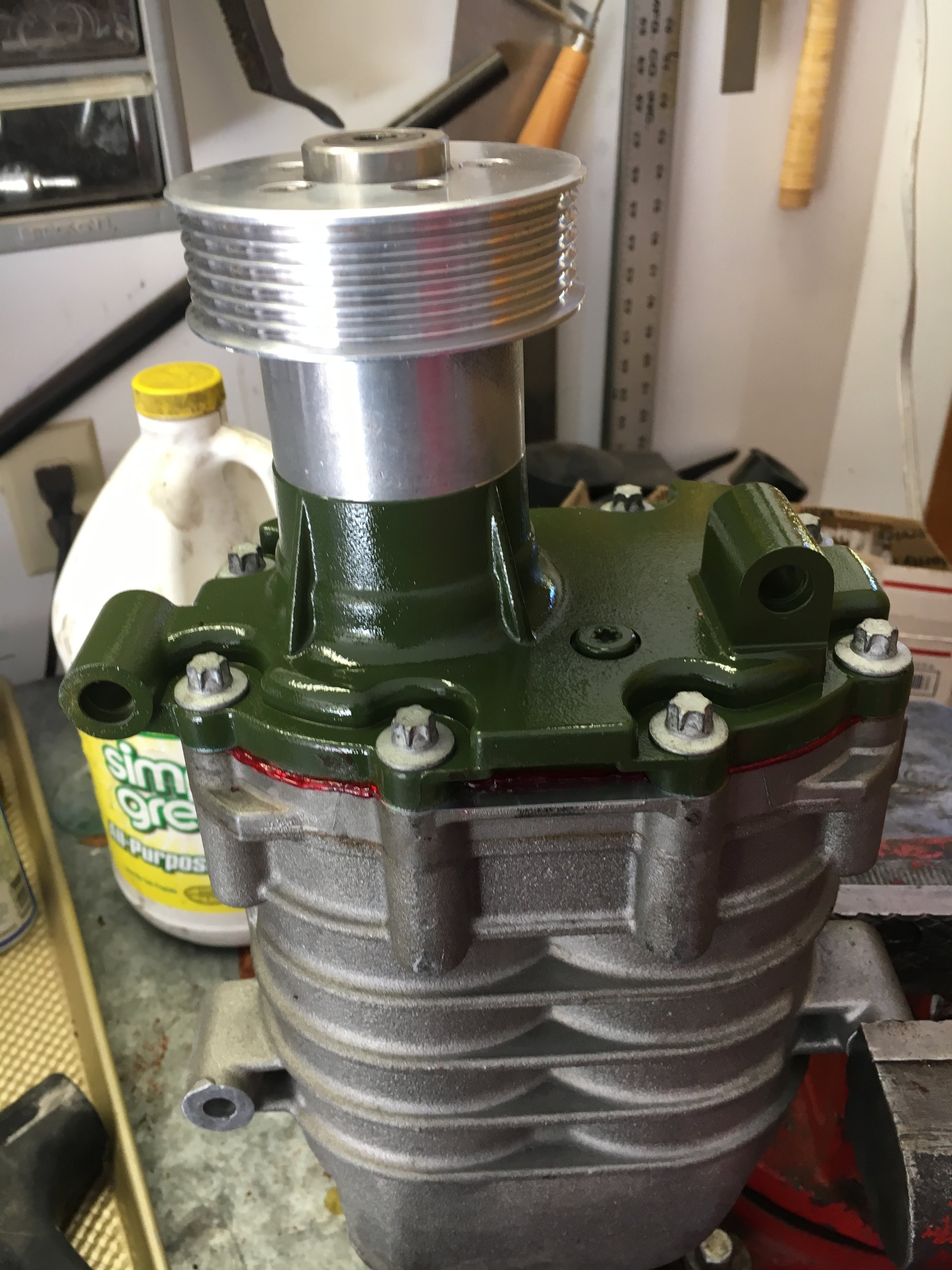
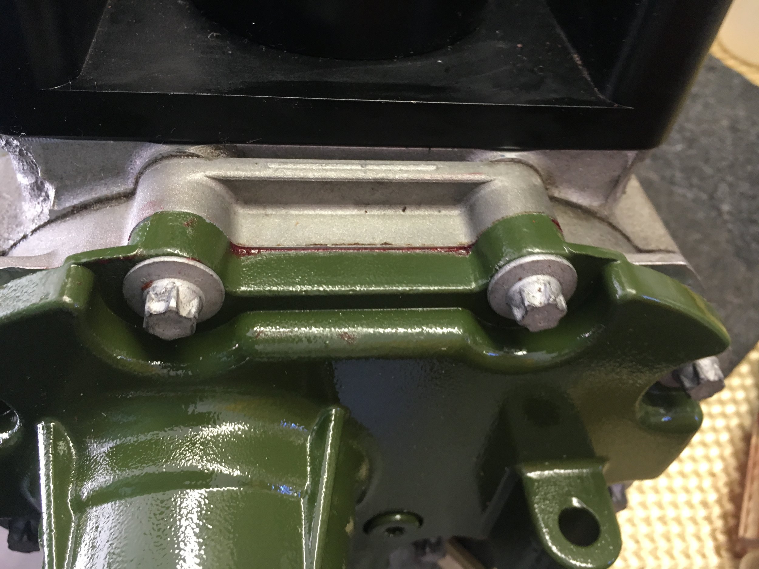
Here is a completely rebuilt snout assembly ready to be fitted, that has been painted OEM olive green to match the engine and mounts on the ‘67 MG Midget test mule featured in these instructions:
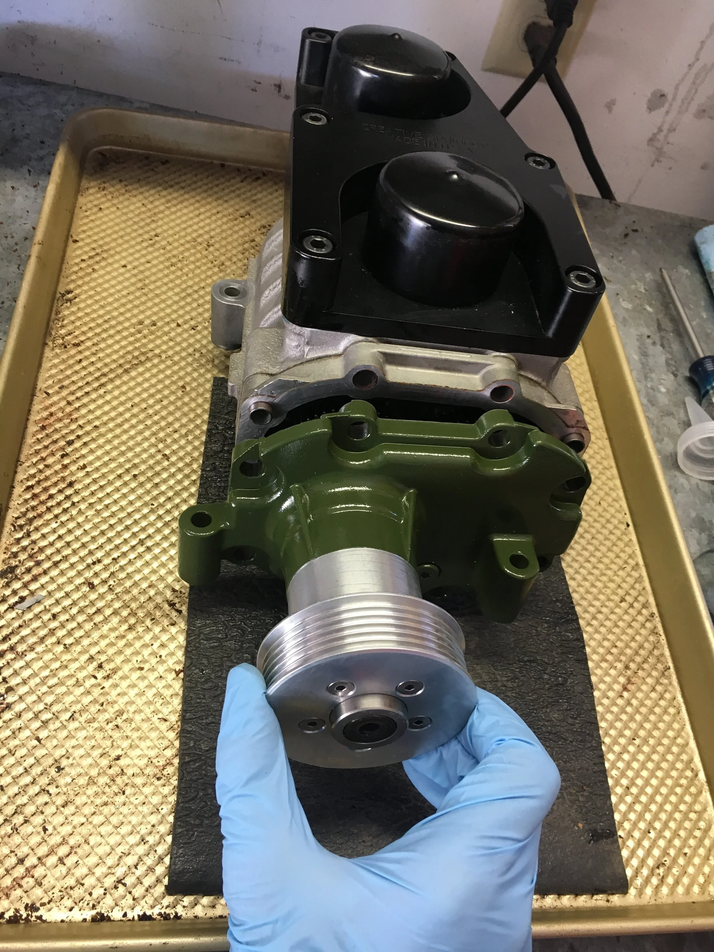
STEP 2 - Replacing the Snout Bearings
This operation requires an arbor press. The press shown in the following photos was inexpensive, and obtained from Harbor Freight Tools. It paid for itself just in this supercharger rebuild, but if you have room for one, it will prove useful over and over when working on a Spridget.
First, remove the OEM pulley as discussed above.
Next, follow the disassembly sequence set forth below, selecting sockets which are as large as possible without binding in whatever recess they must go into.
Essentially, you first press the shaft down and out of the housing, then flip the housing and press the frontmost bearing out through the front of the snout, and finally press the bearing and splined hub off of the shaft:
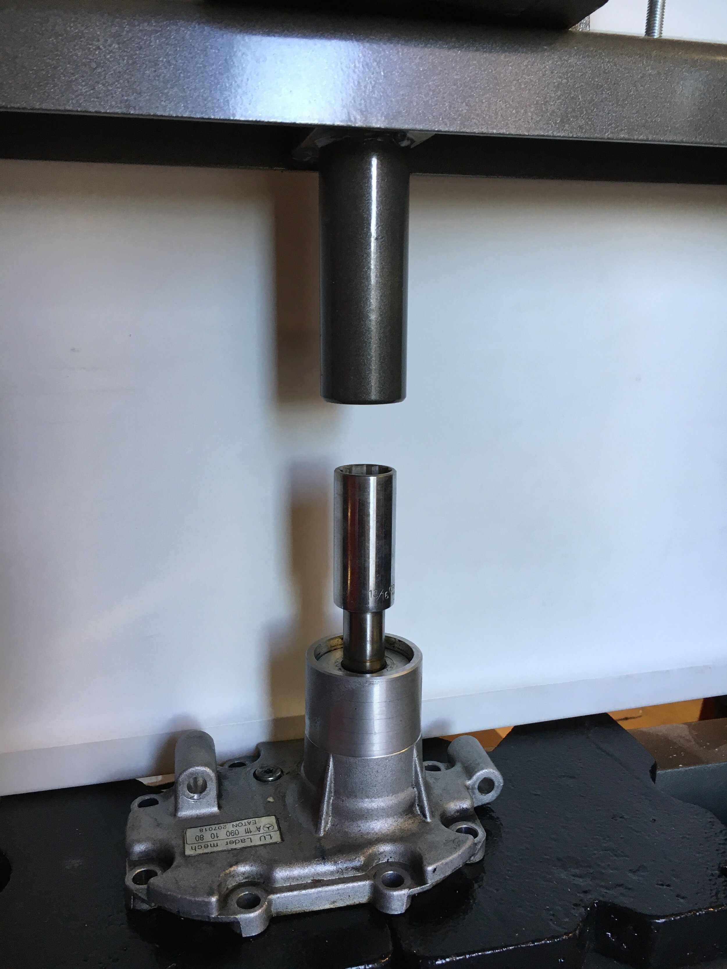
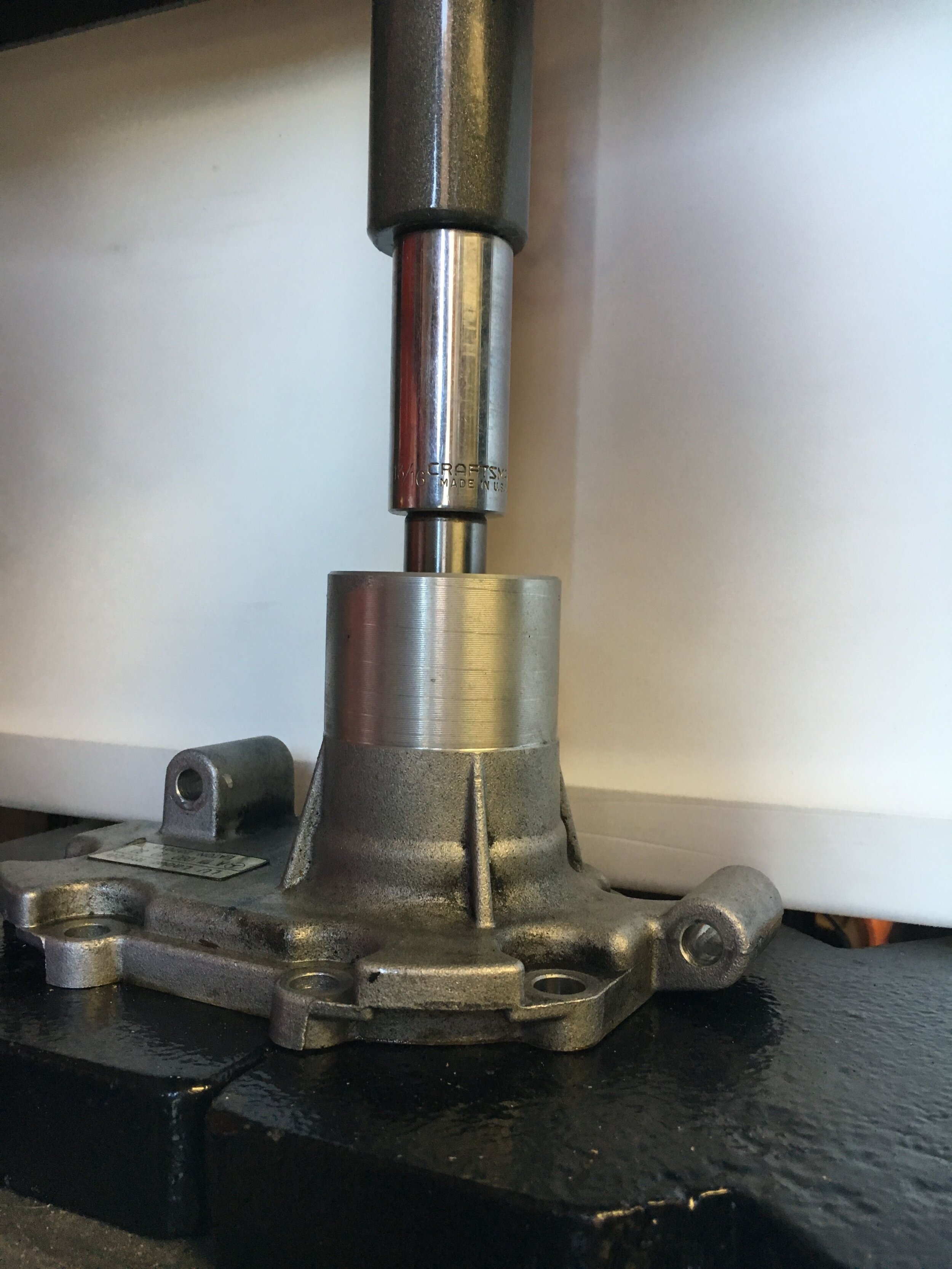
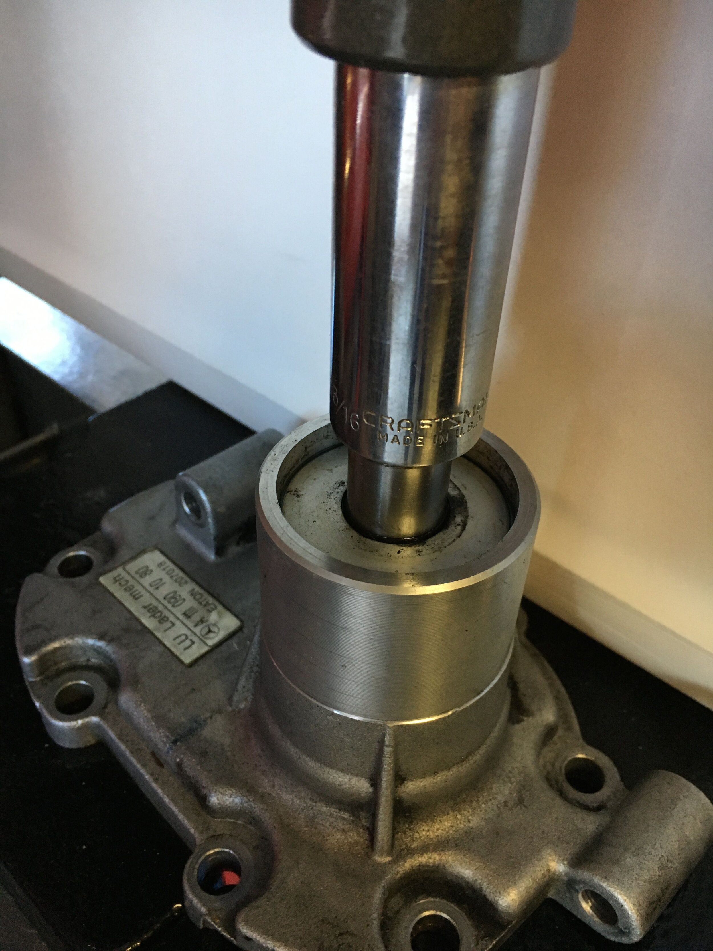
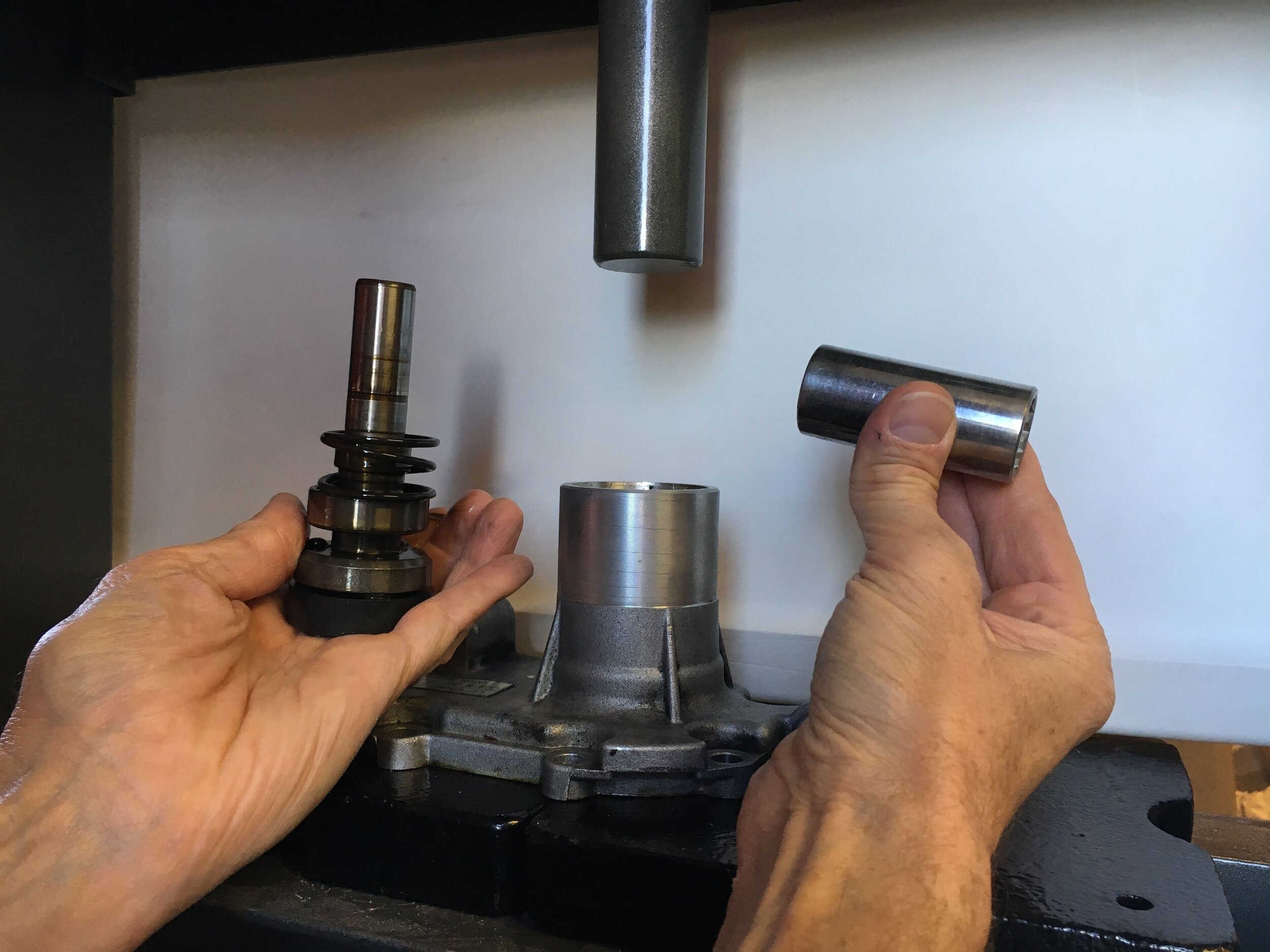
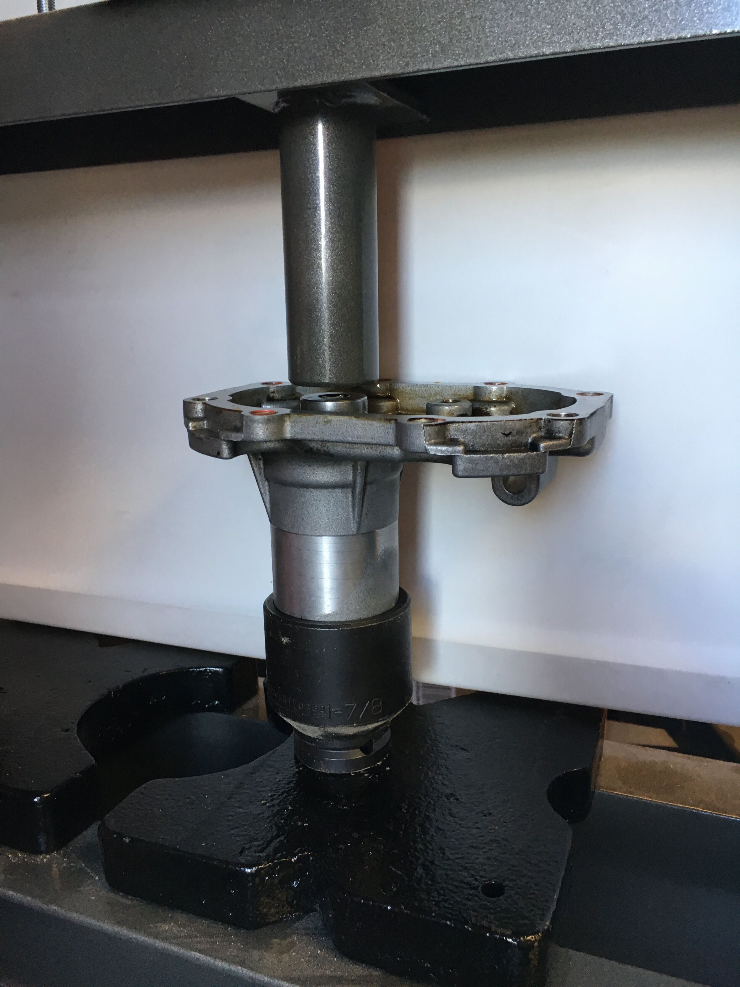
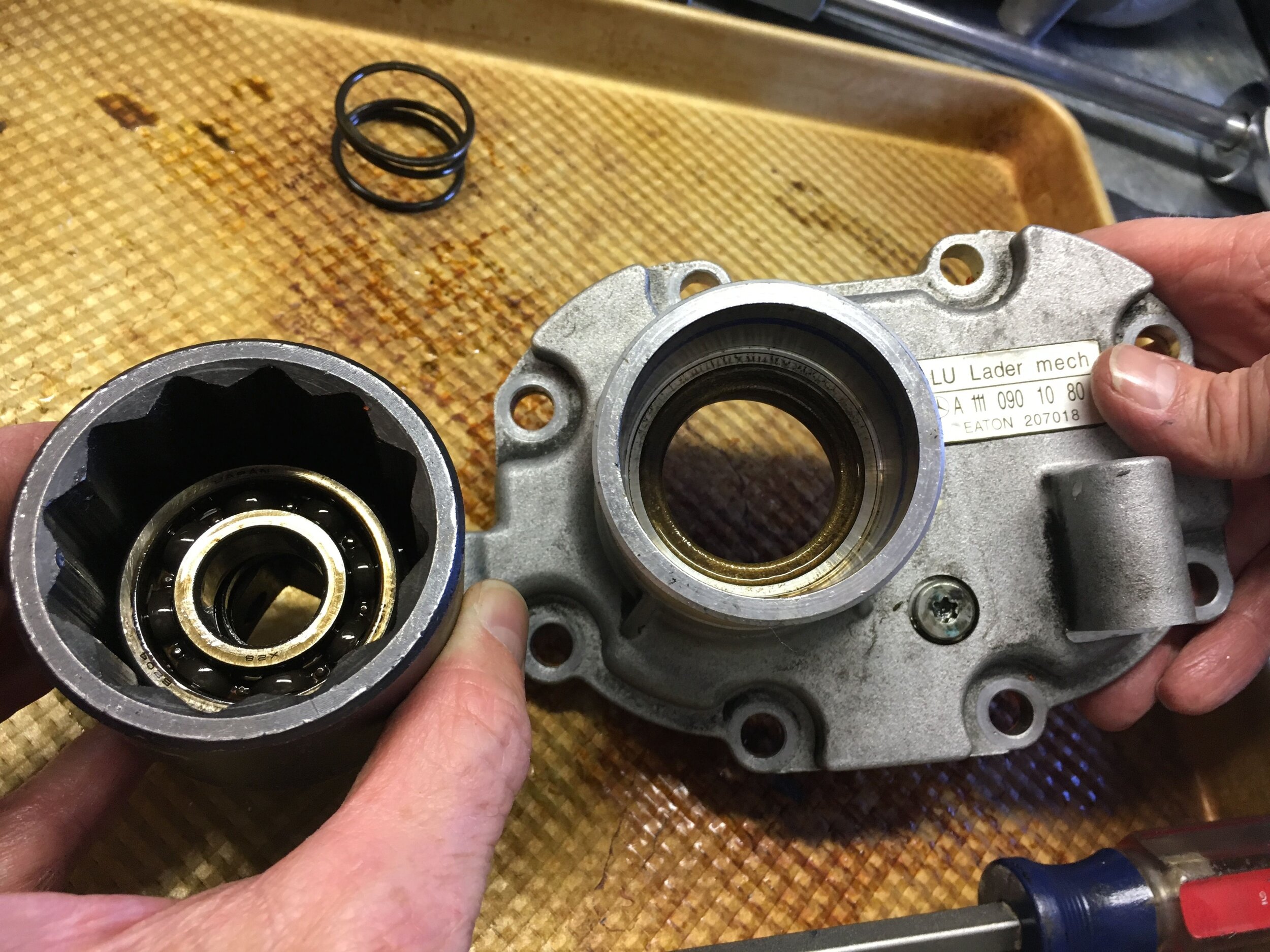
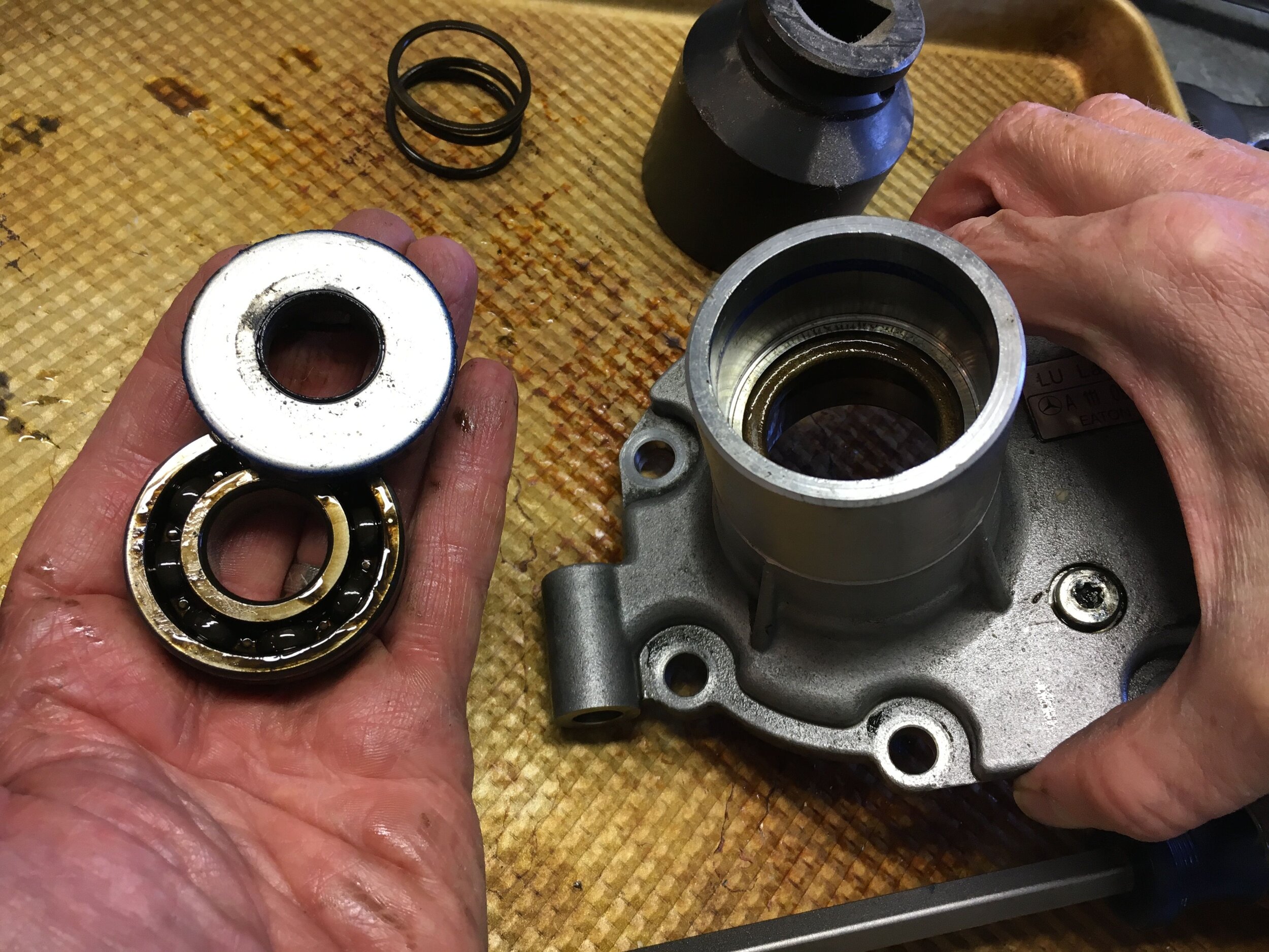
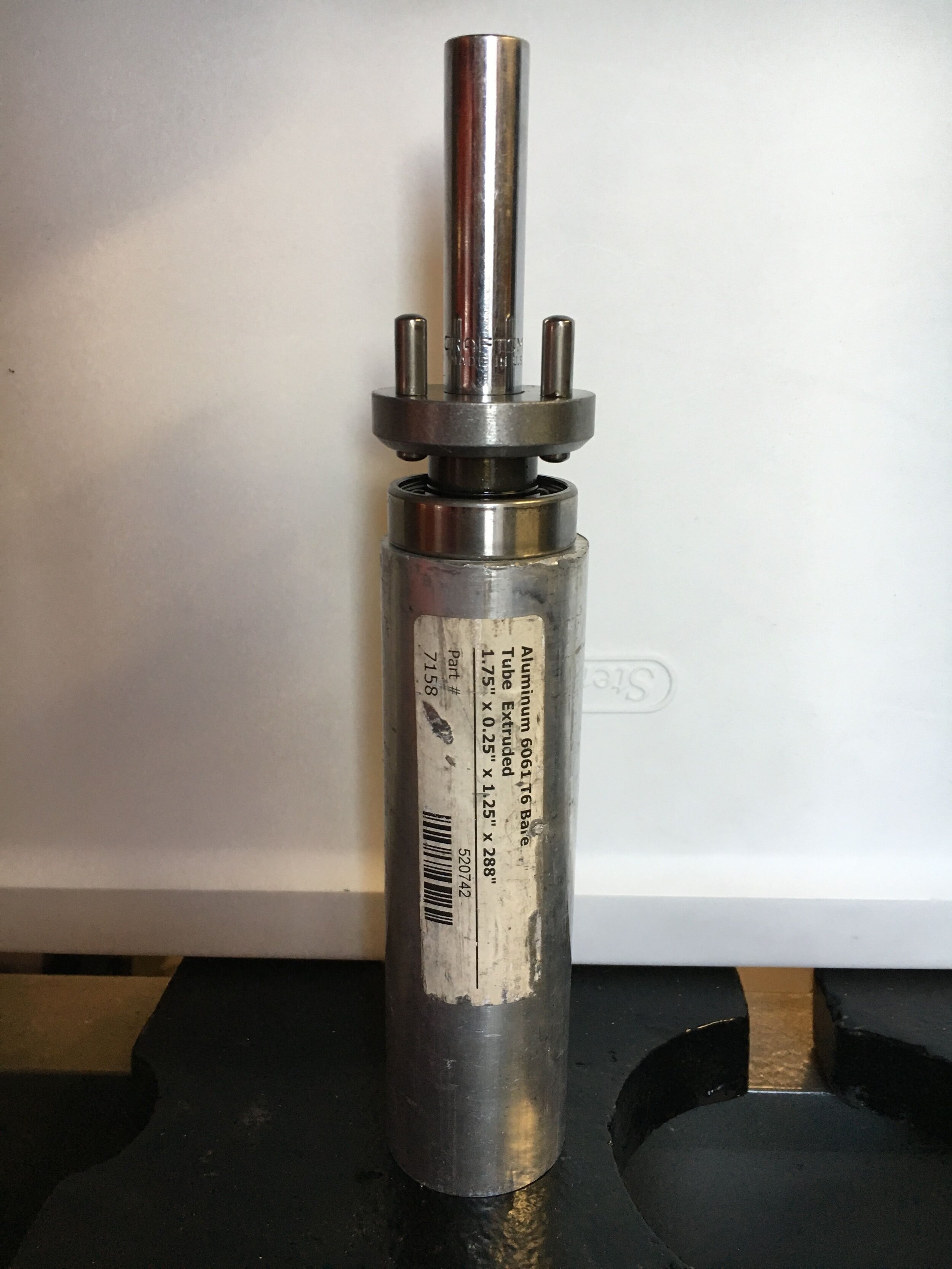
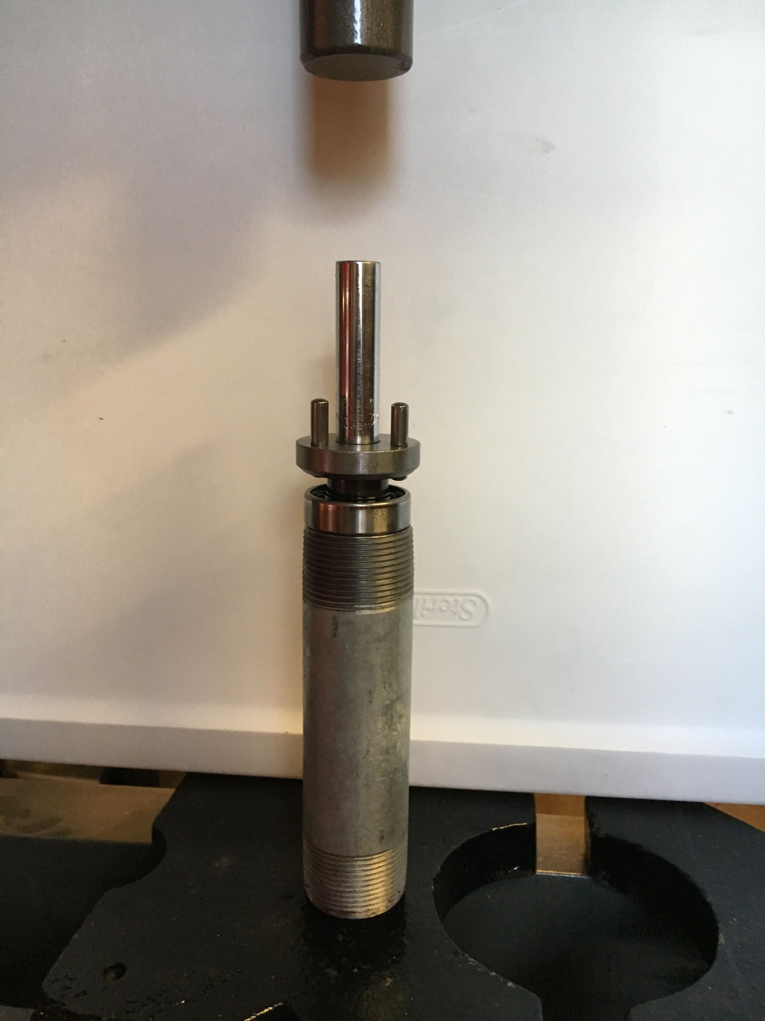
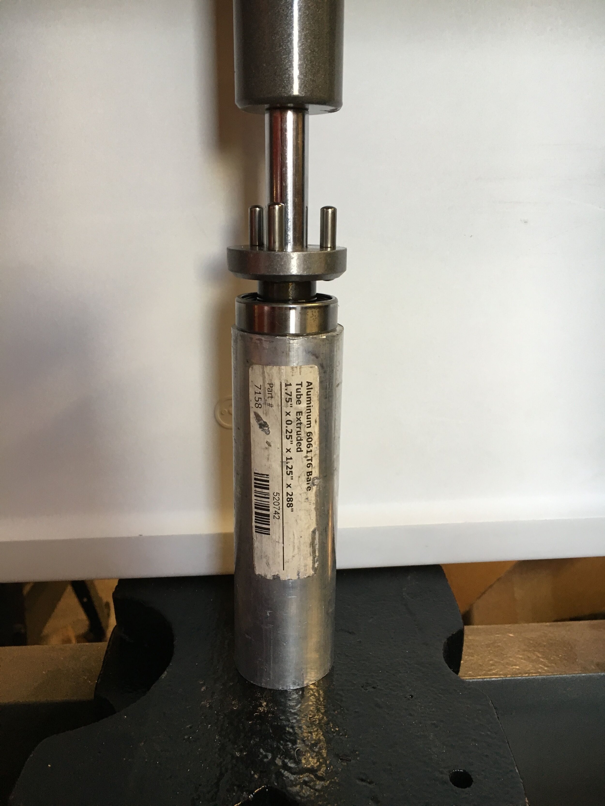
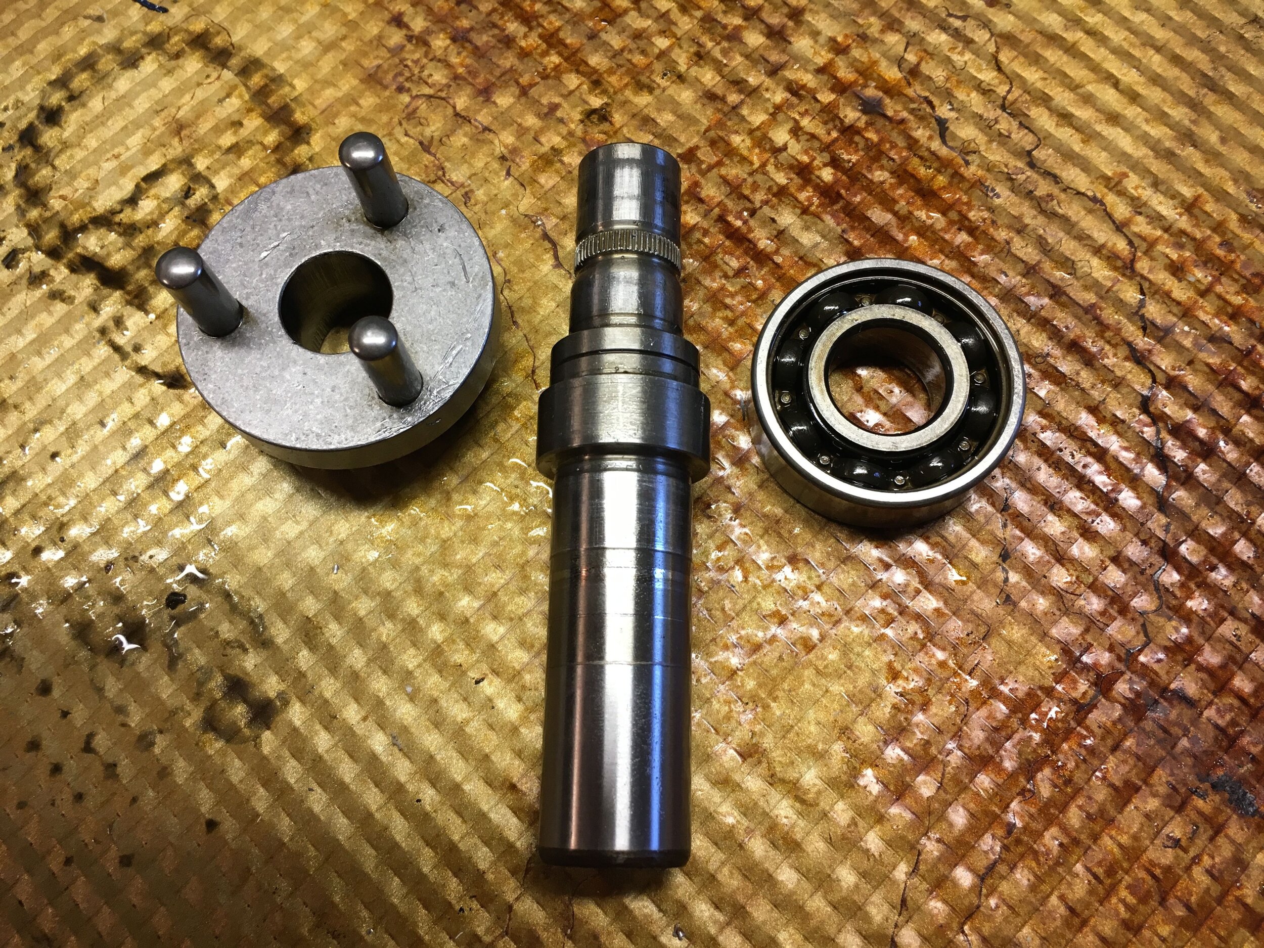
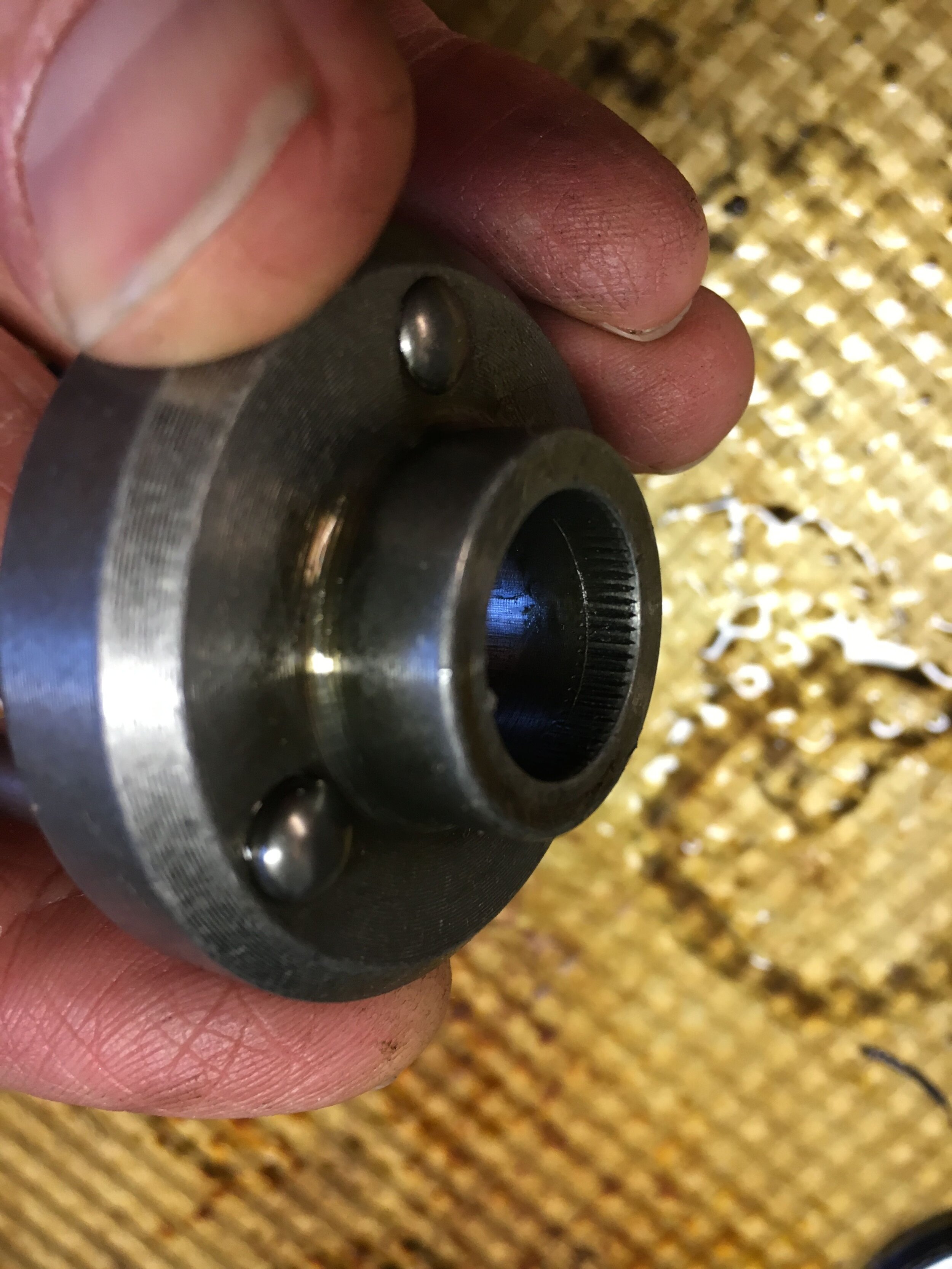
Now, reassemble the hub and bearings, proceeding in reverse order, and finally press in the front seal, retaining clip, and the Smoothflow modular pulley hub:
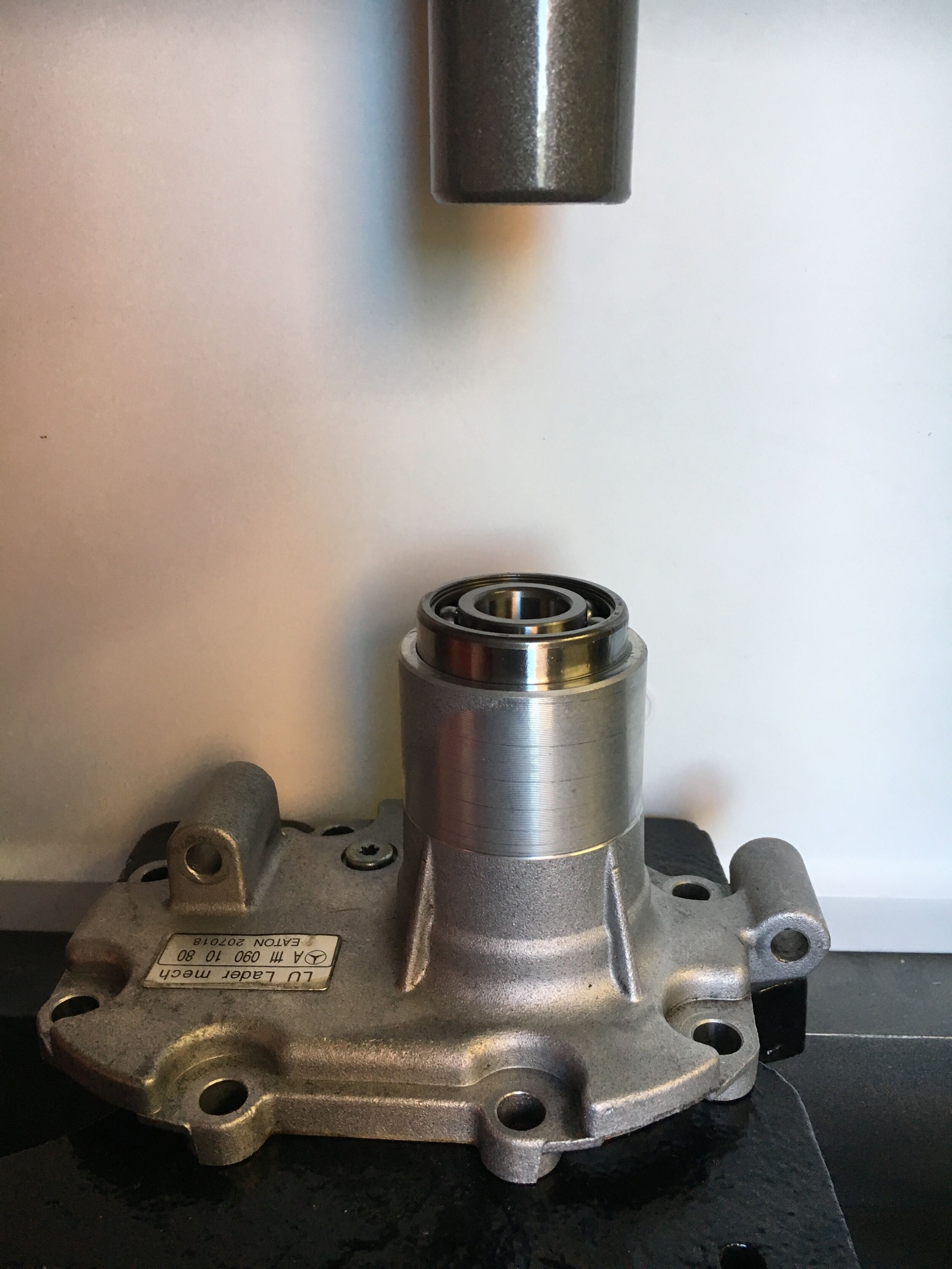
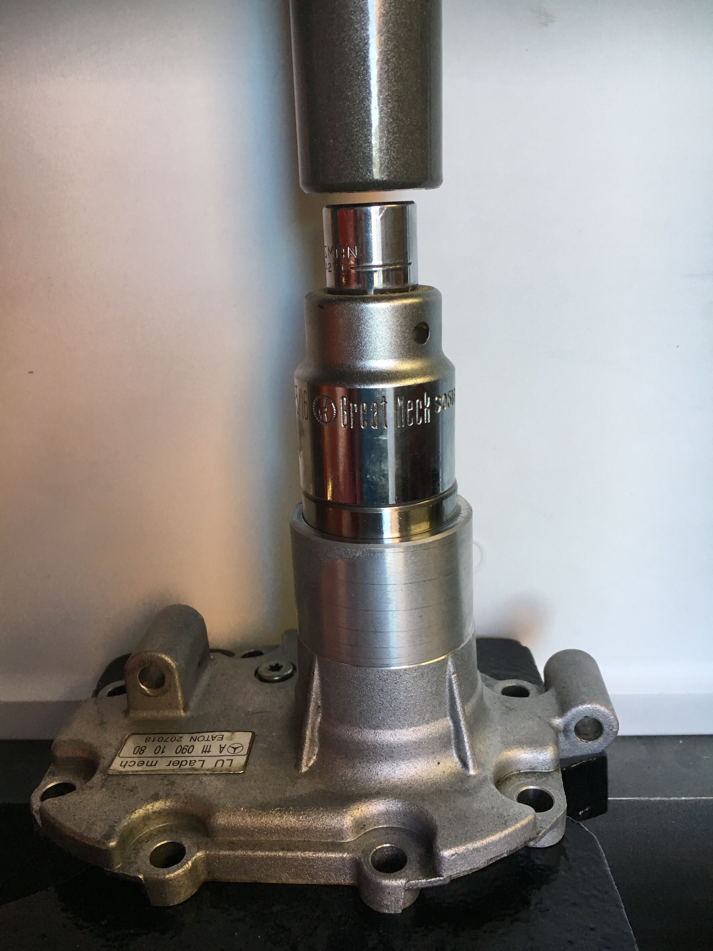
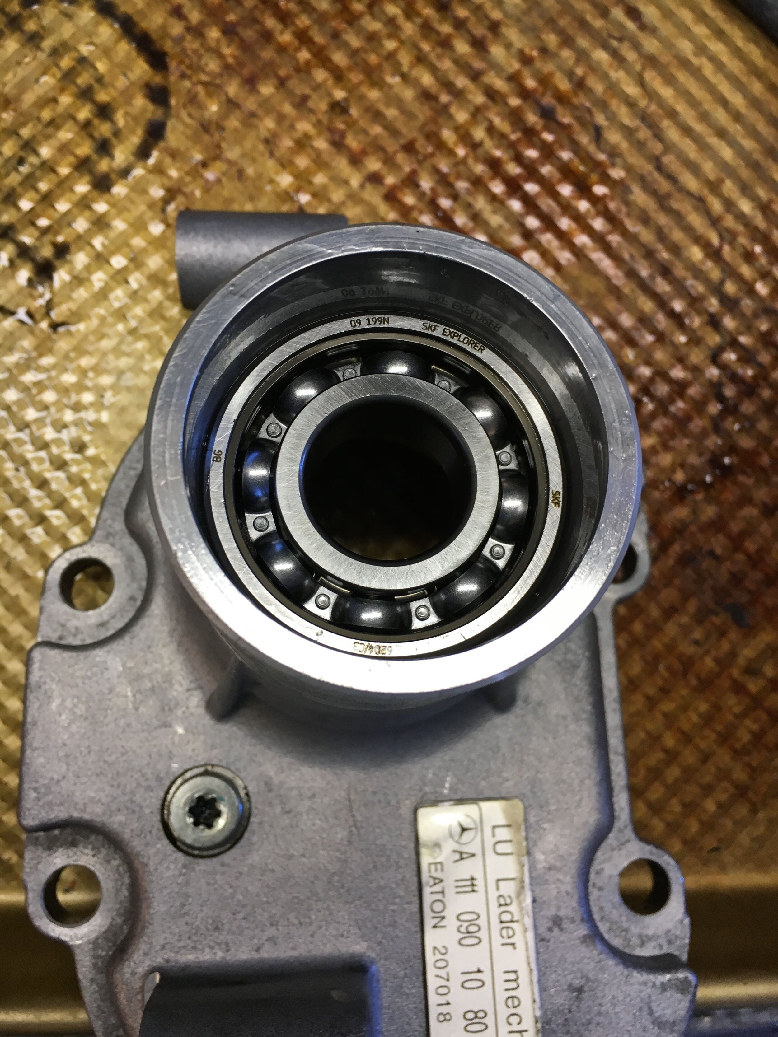
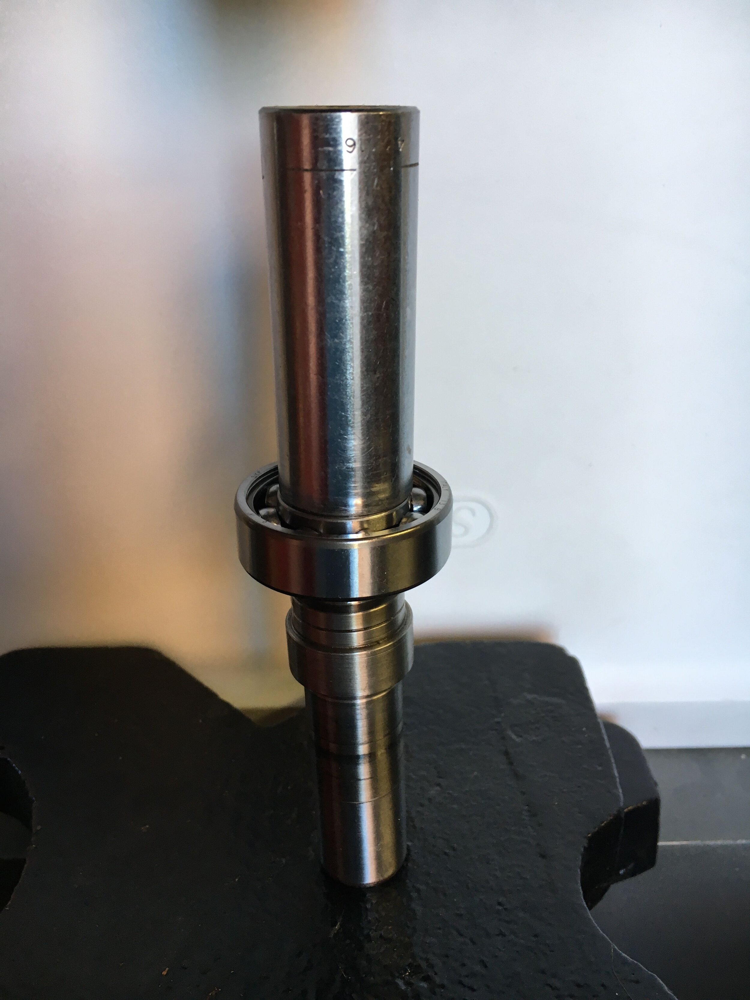
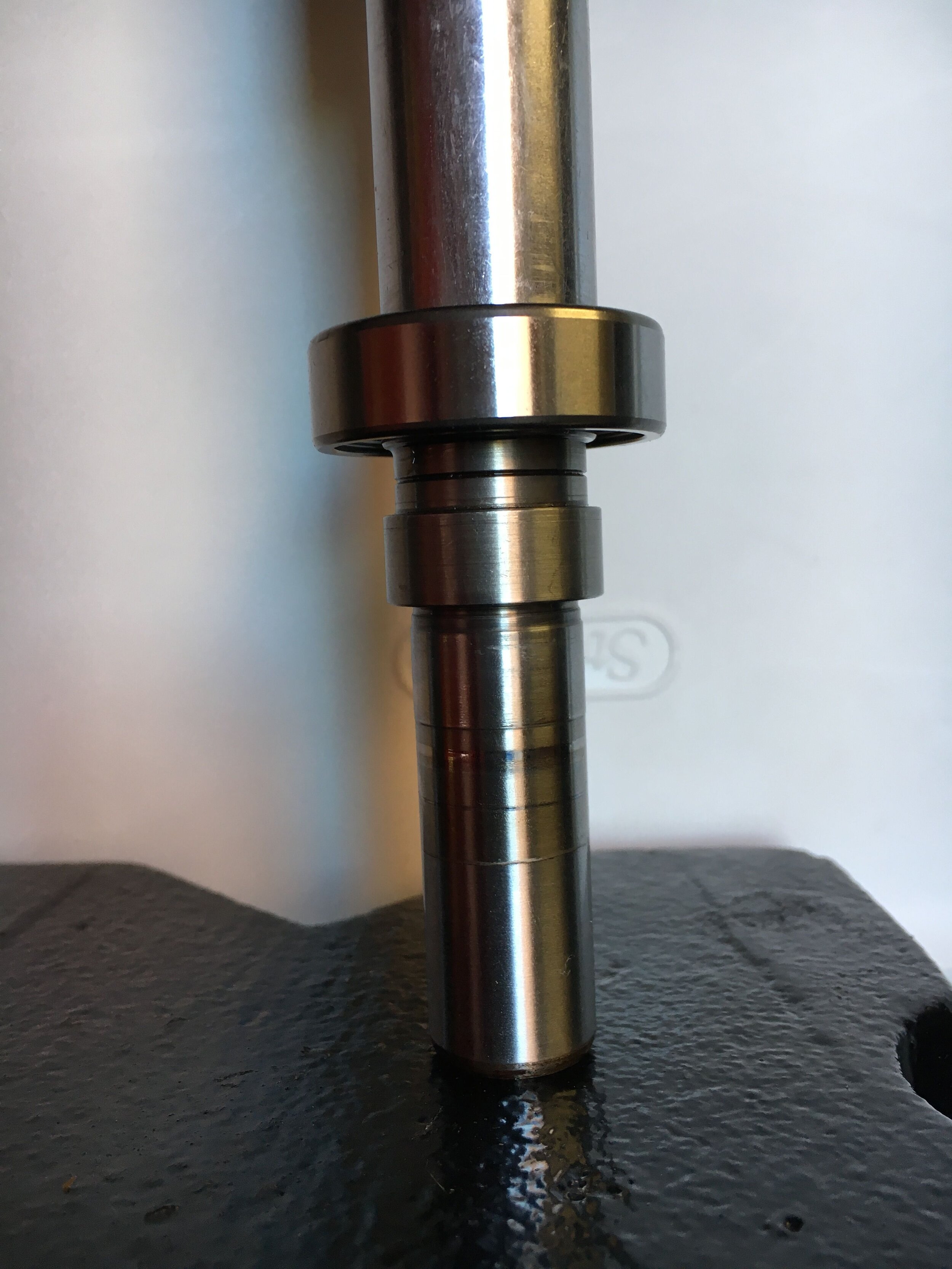
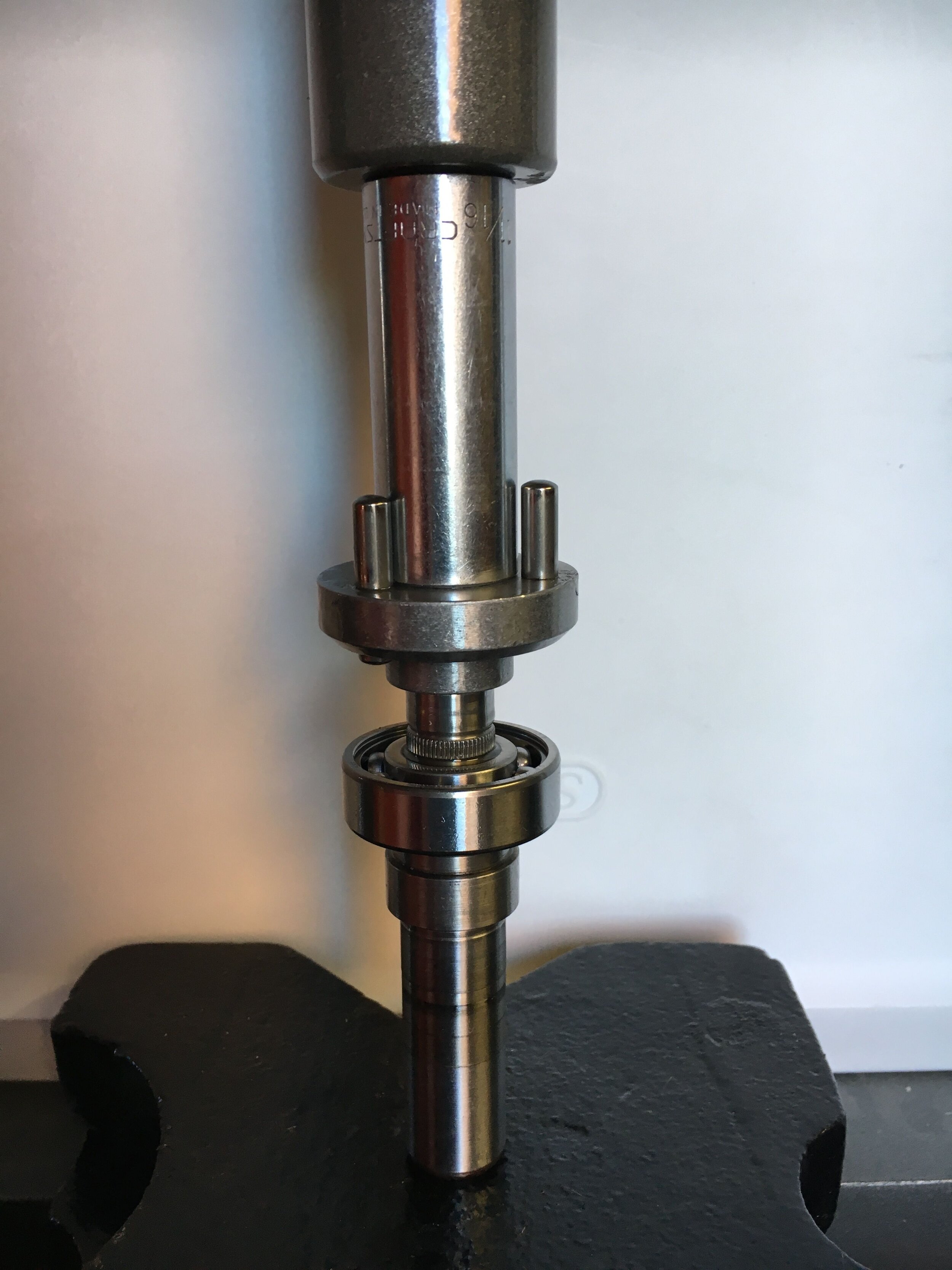
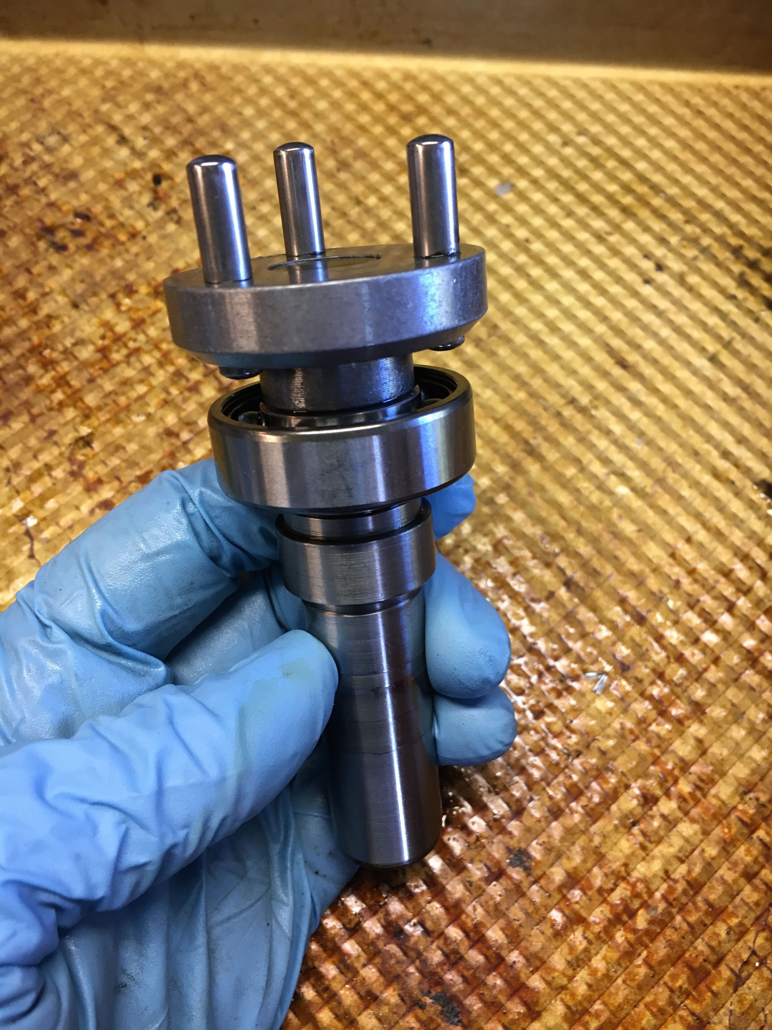
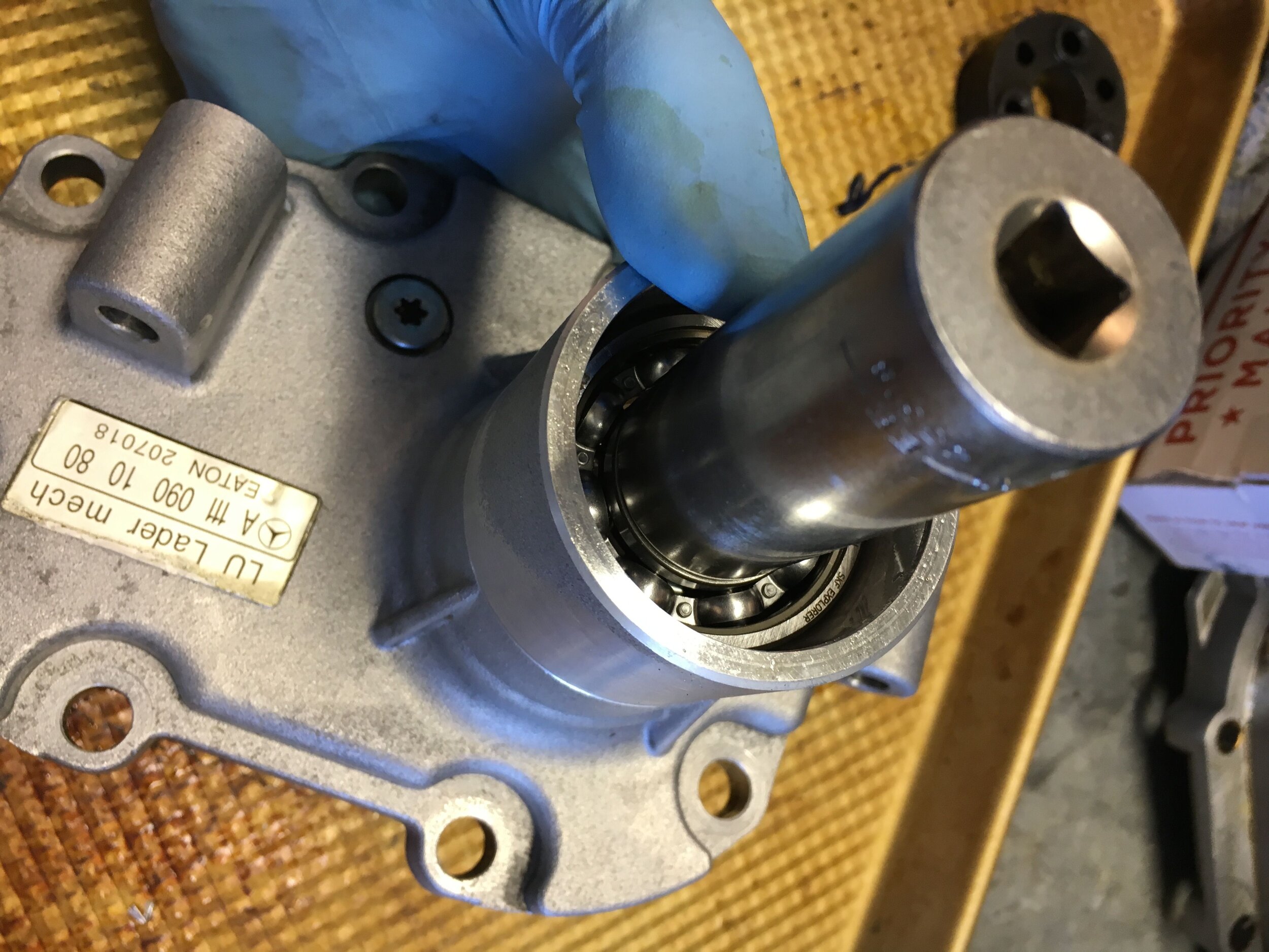
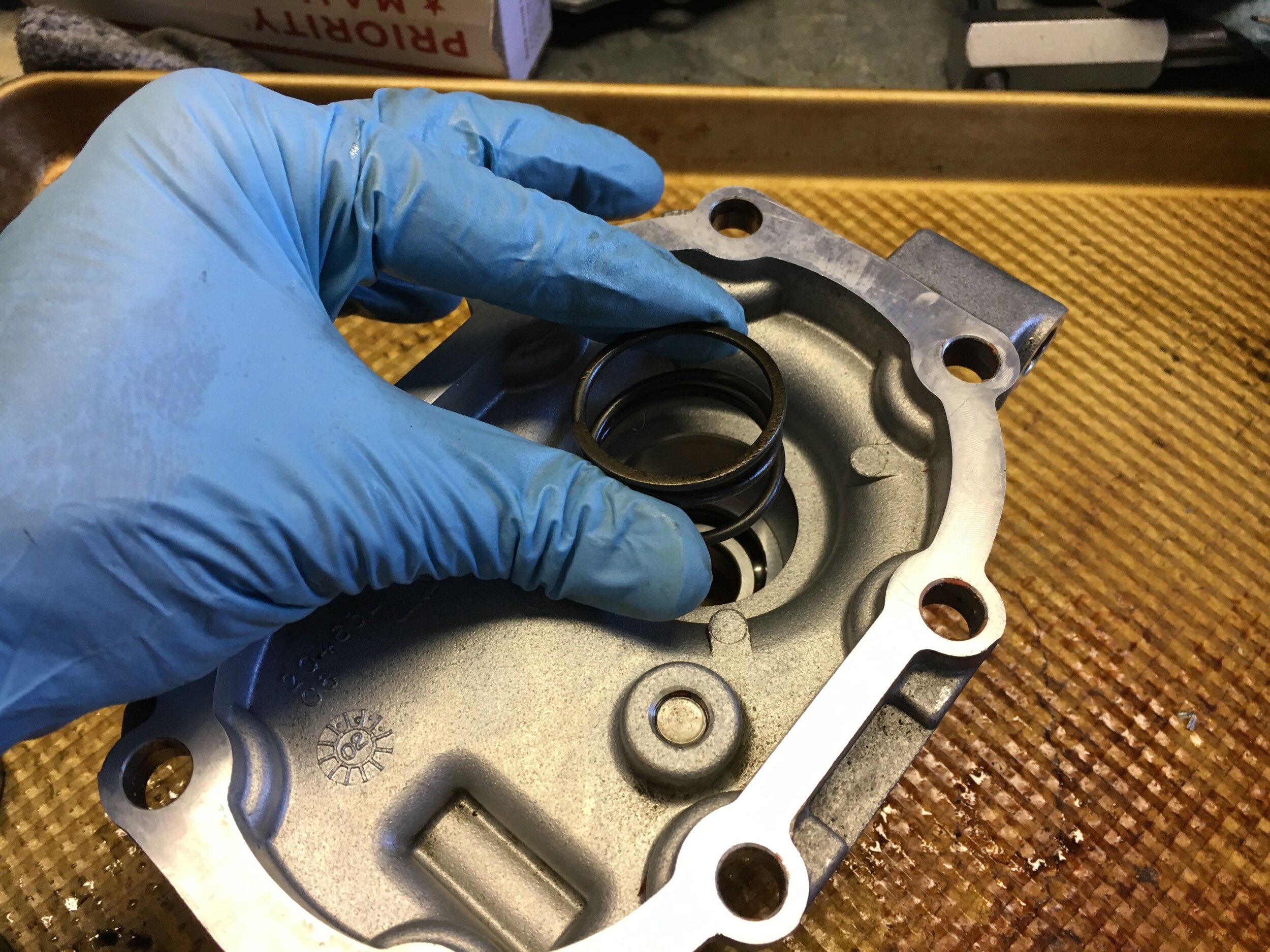
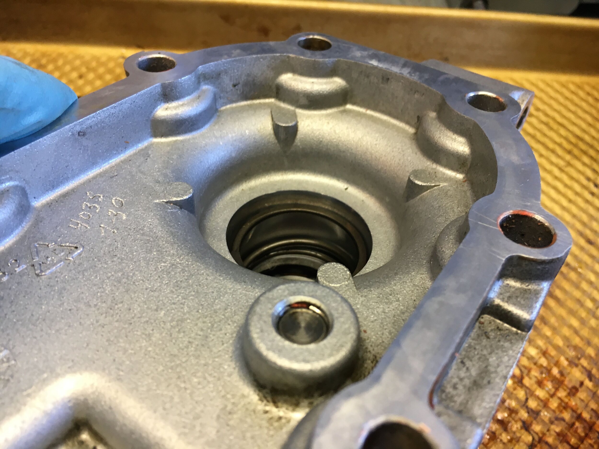
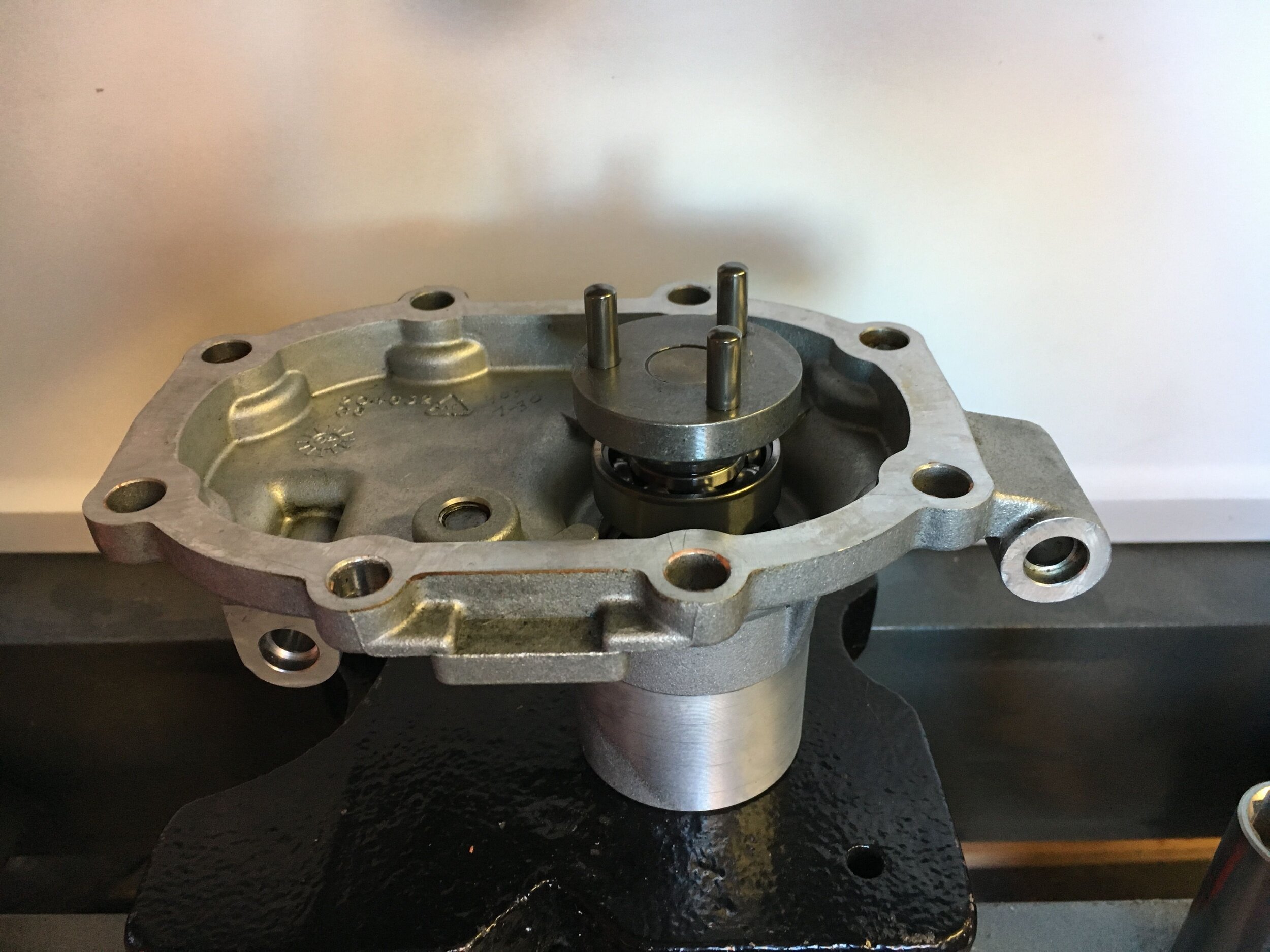
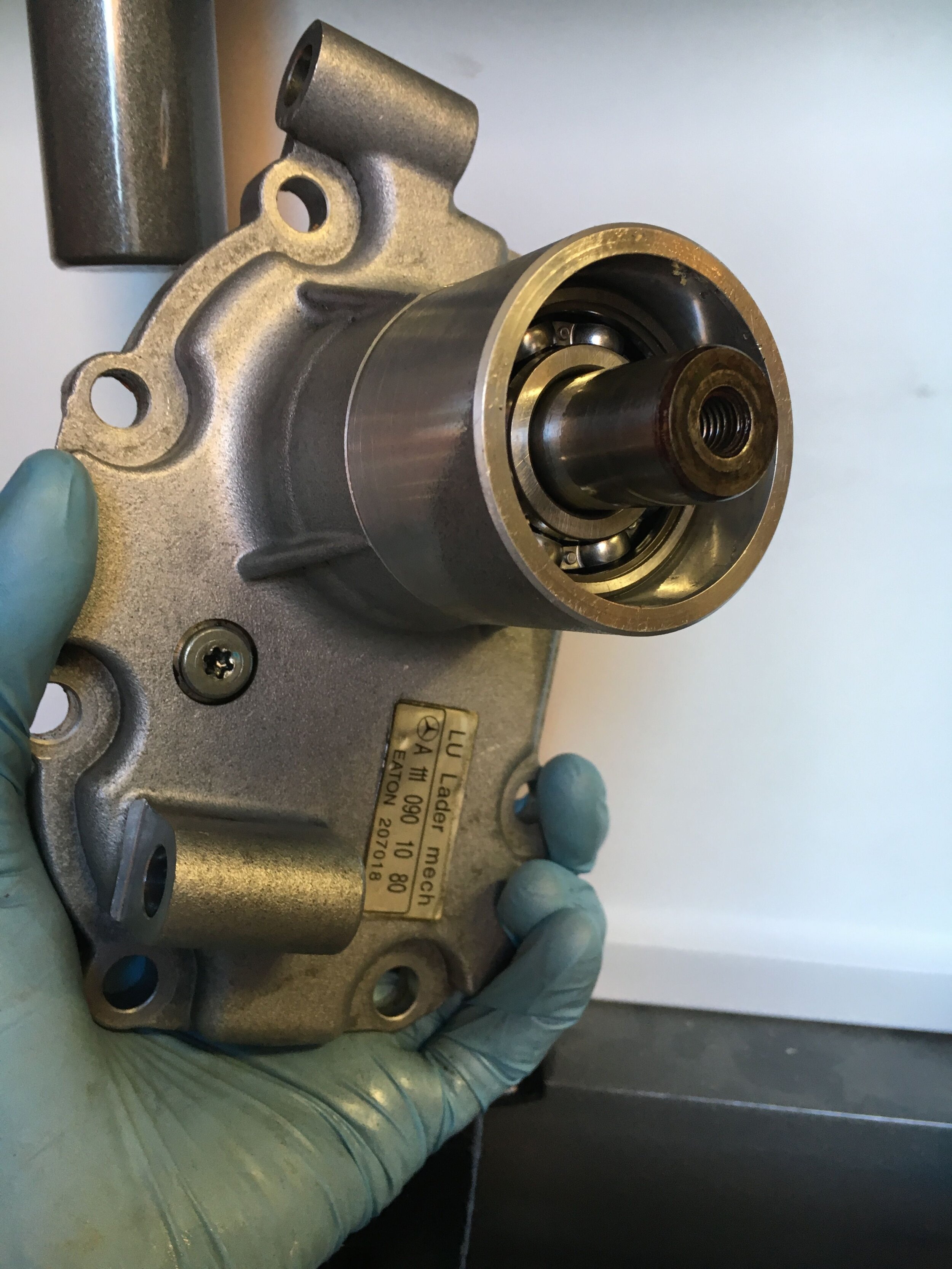
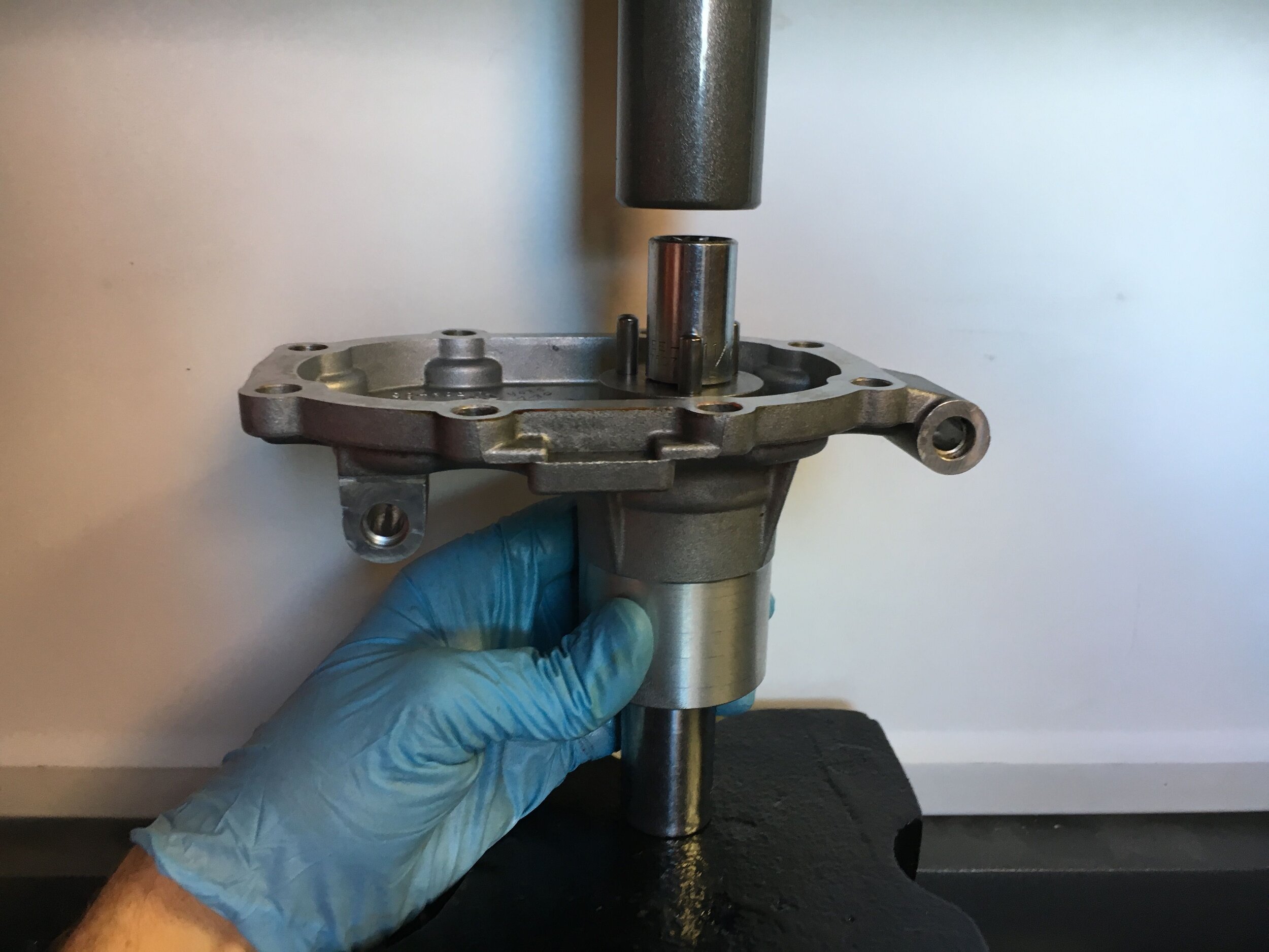
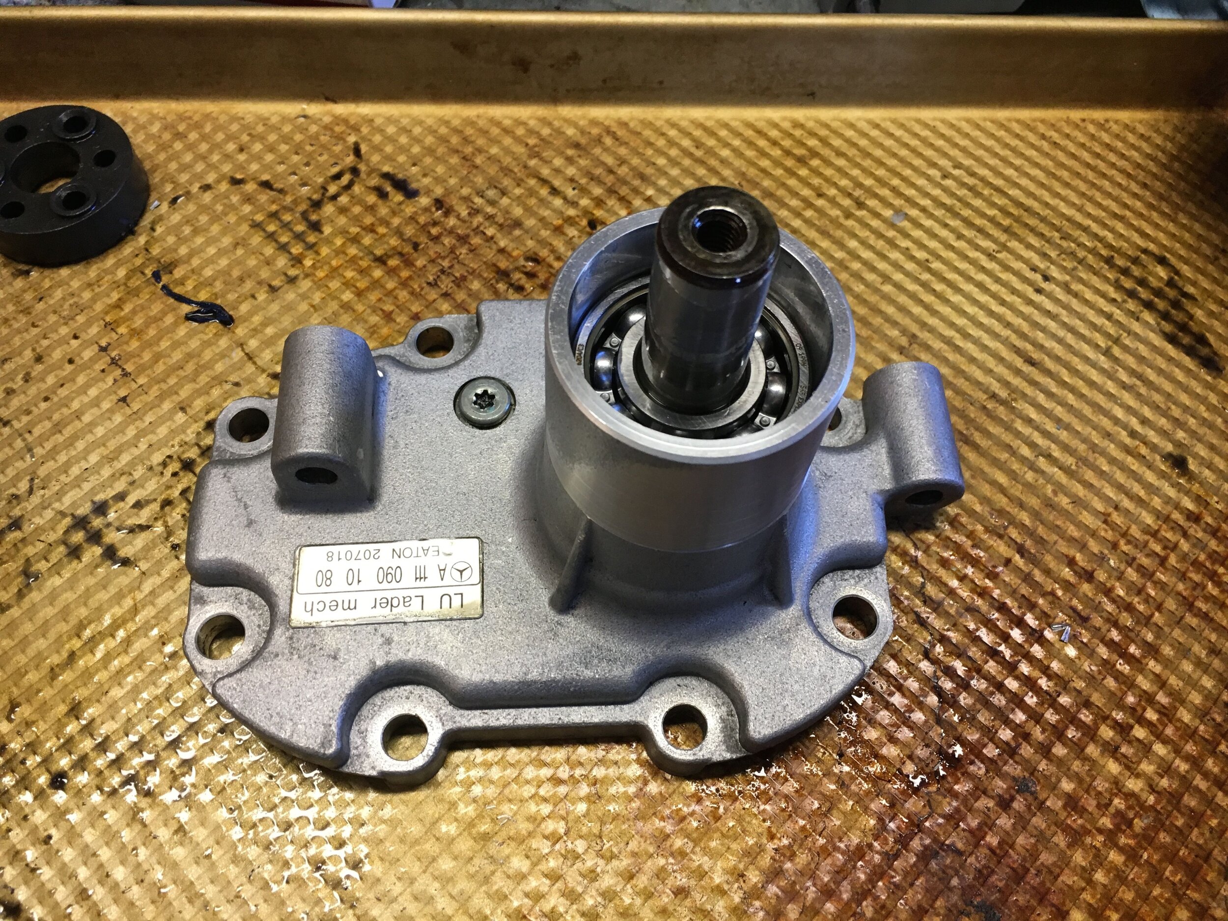
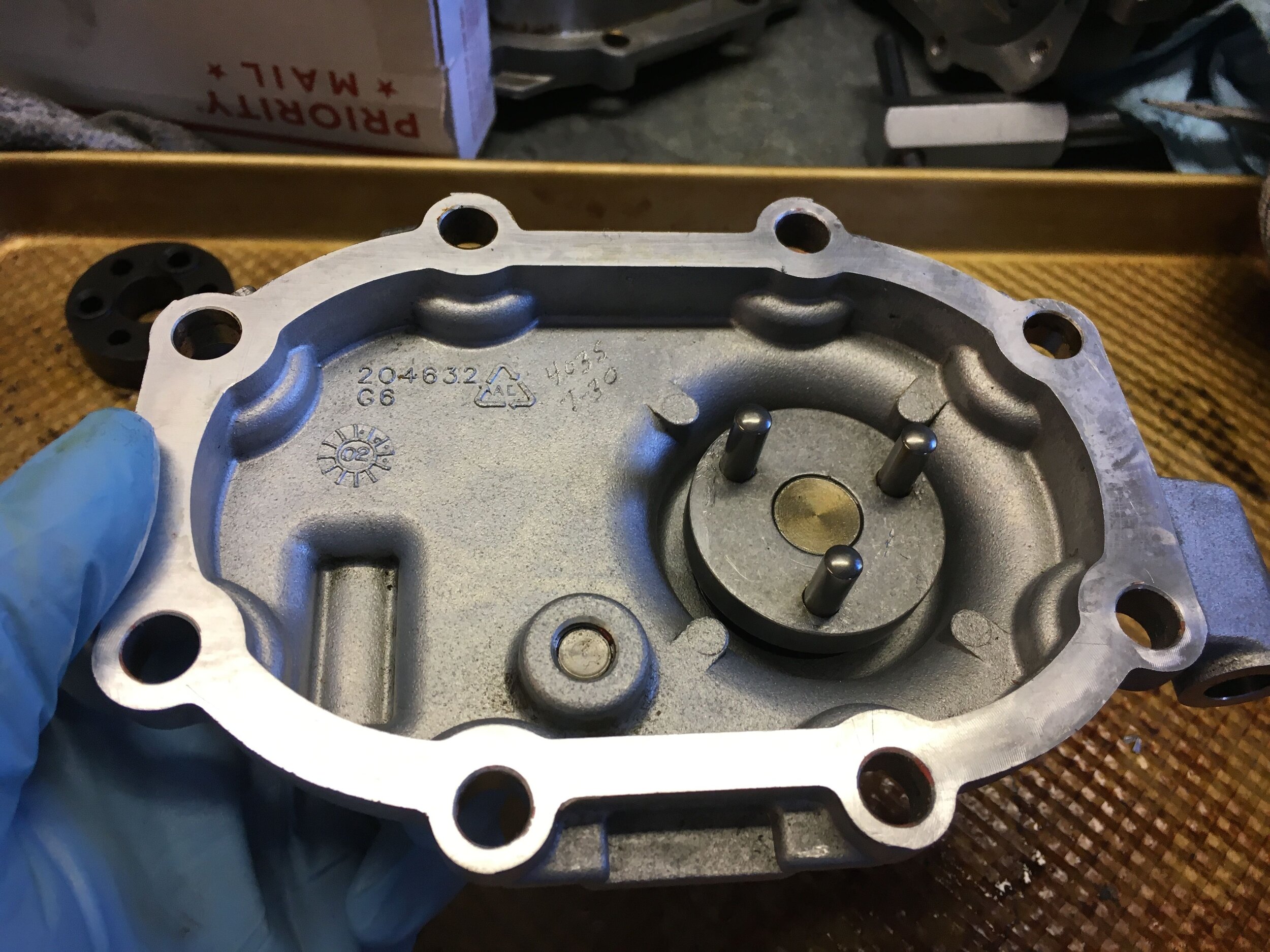
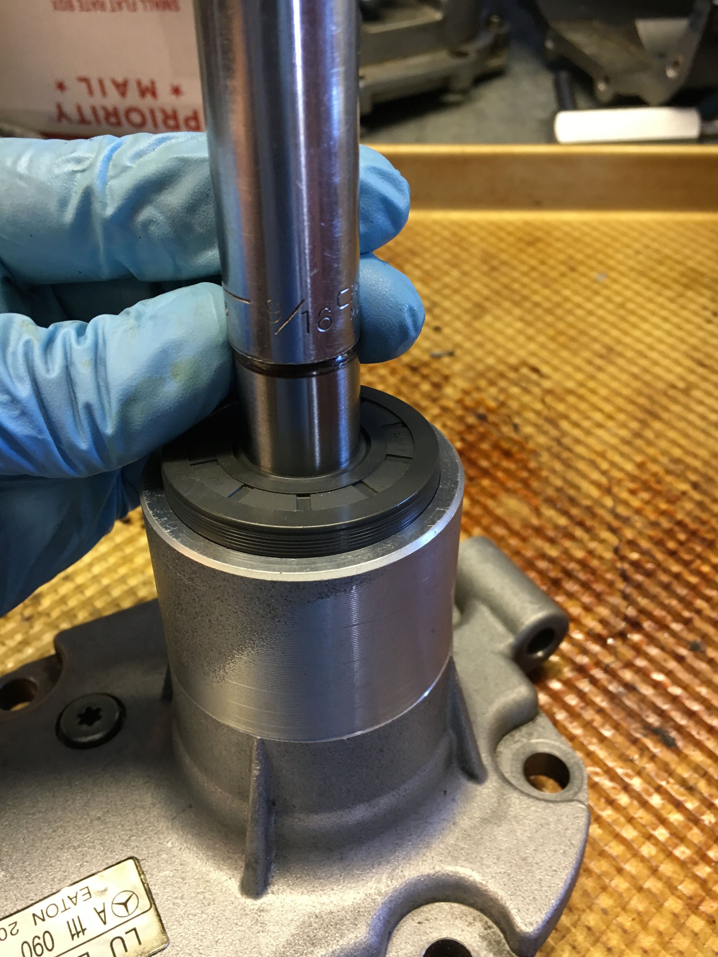
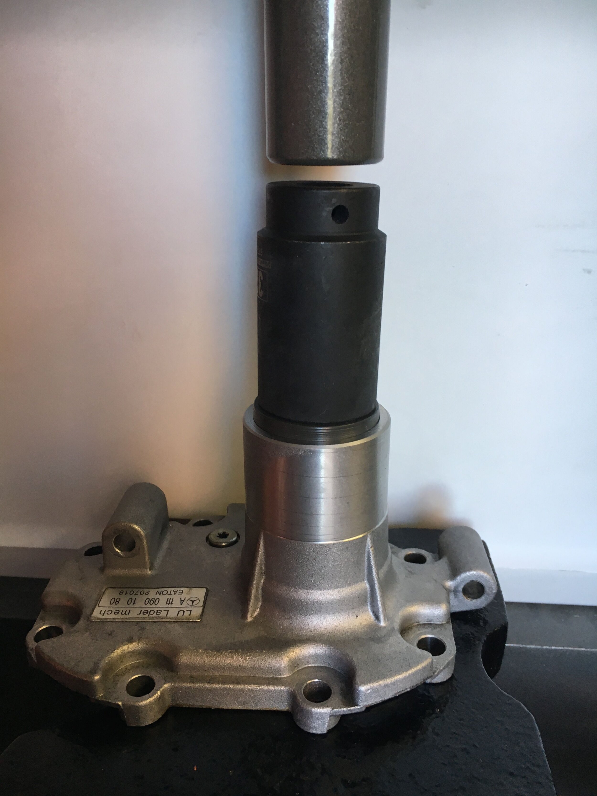
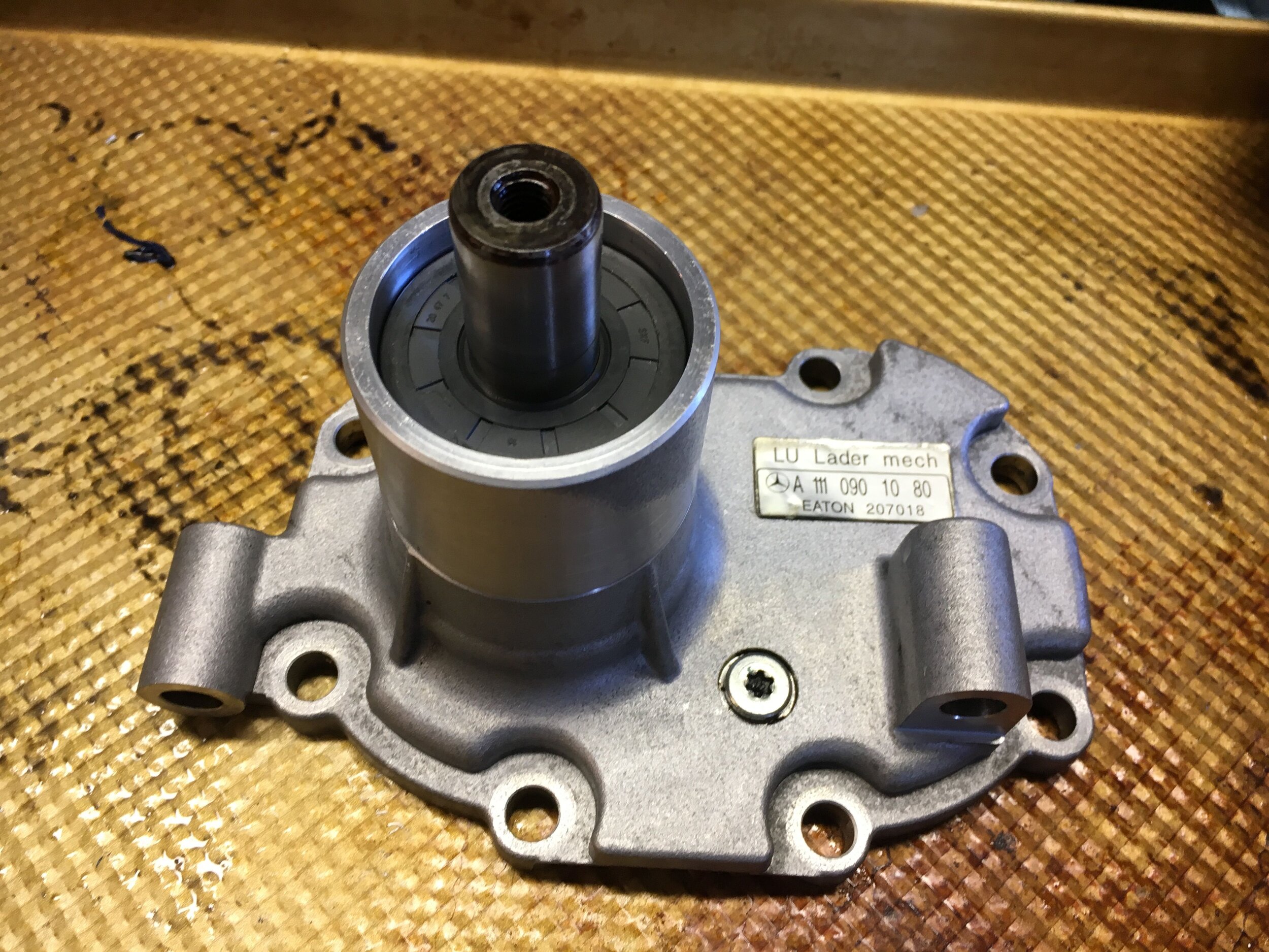
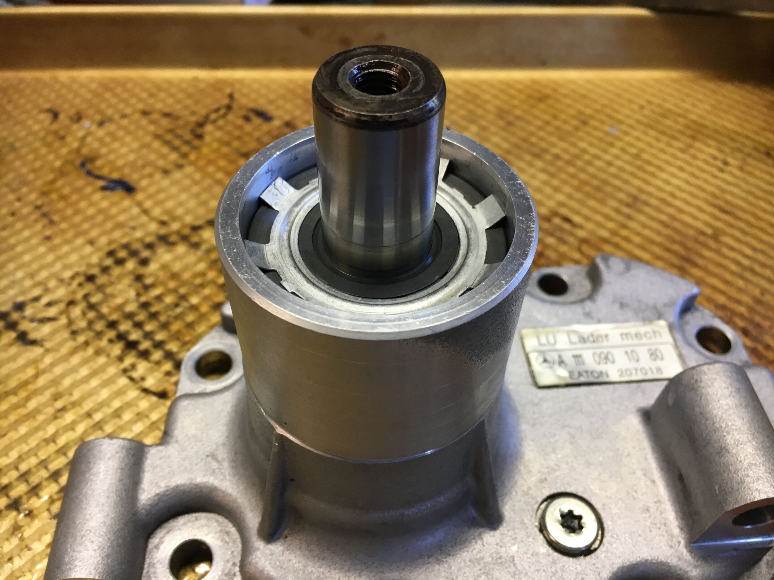
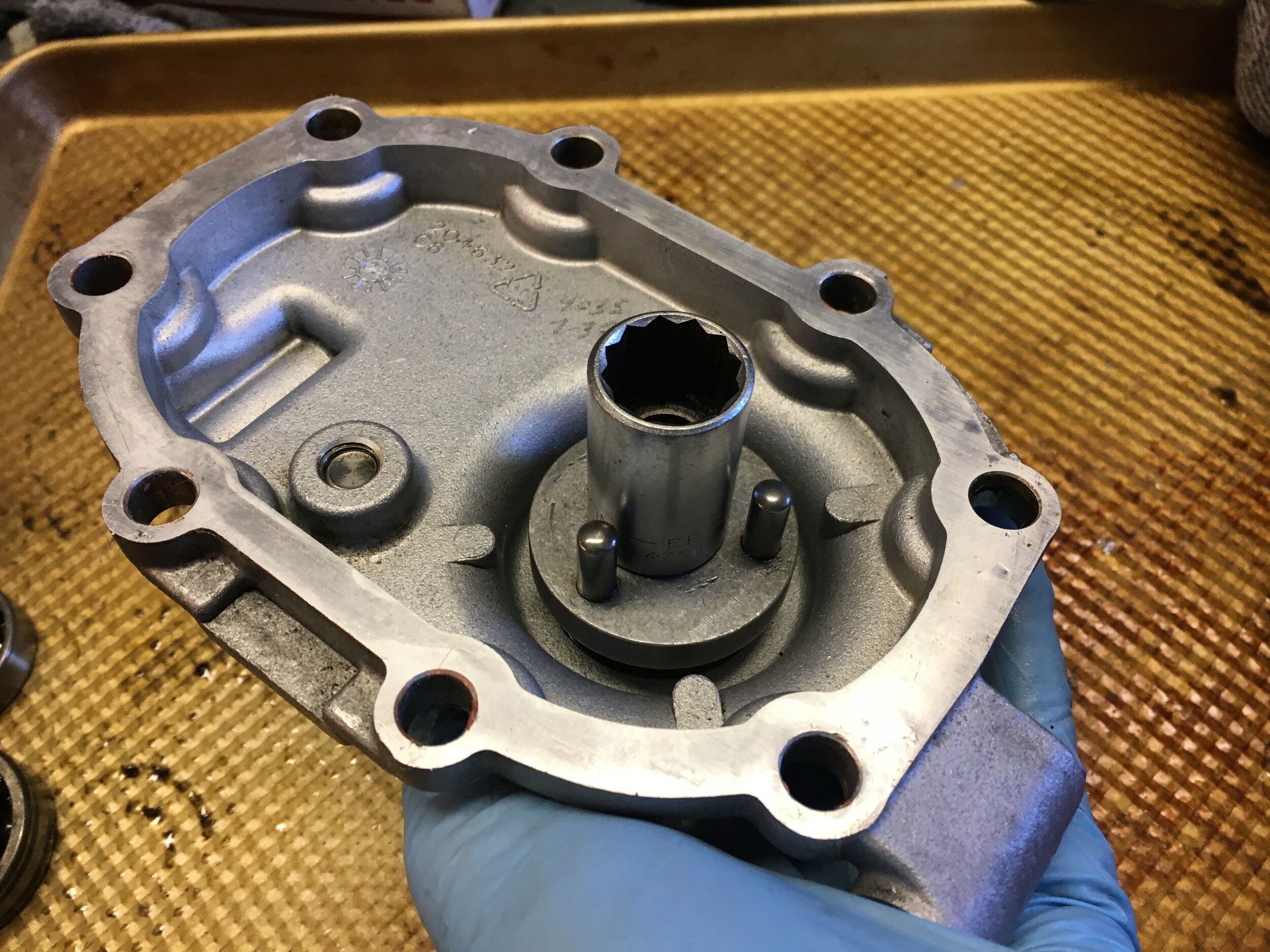
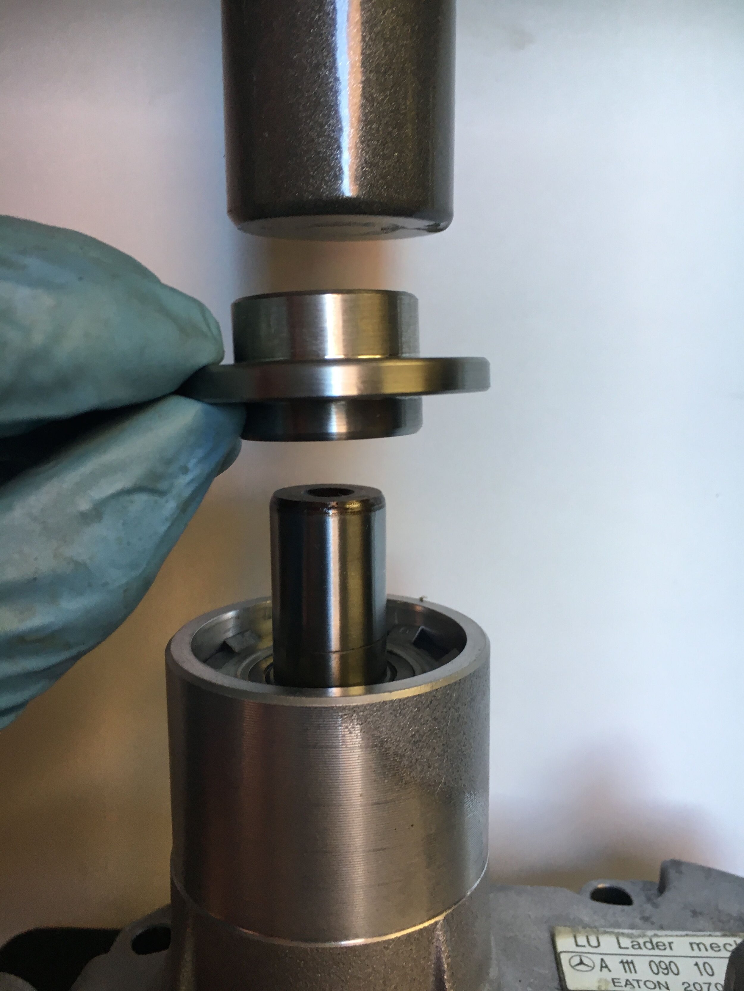

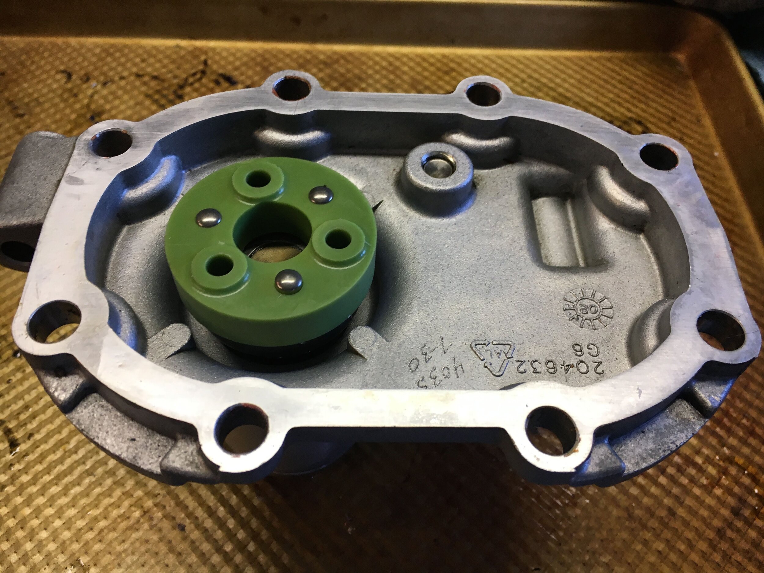
Note that you install the plastic coupler with a couple of firm smacks with your hand, or with a plastic dead blow hammer.
Finish the job by reinstalling the snout assembly and adding the correct amount of synthetic supercharger oil to the gear box as discussed here.
install a ‘stealth’ cold air intake
It is easy to direct cold air from the high-pressure area behind the car’s grille onto the K&N air filter tucked under the left-hand fender or wing. All that is required is a 3” air duct mounting plate (see the parts list), a length of aluminized 3” HVAC or automotive flex hose, and appropriate hose clamps.
We used a 3” bimetal hole saw to cut the hole, drilled the bolt holes using the plate as a template, expanded the duct as necessary to reach the air filter. The effectiveness of the system is evident in the last image in this series: