
How to install Rear Disc Brakes on a Spridget*
*Note: creative spridgets no longer sells rear disc brake adapters. This web page will continue to be hosted for informational purposes.
Please contact us if any part of these instructions is unclear, or to have your installation tips, photos, or videos posted on this page.
For an overview of this project, click here.
For FAQs, including fitment limitations, click here.
For a parts list, click here.
PART I - MOUNTING THE ADAPTER PLATES
part ii - preparing and mounting the discs
PART III - CALIPERS and PADS
PART IV - BRAKE LINES
PART V - PARKING BRAKE LINKAGE
part vi - proportioning valve and bleeding system
PART I - MOUNTING THE ADAPTER plateS
STEP 1 - Support car securely on jack stands with wheels free of ground. Never work around or under a car unless it is properly supported. In other words, not like this:

STEP 2 - Remove rear wheels, brake drums, shoes and springs, half-shafts, and hubs. You will need a 1-7/8" socket for the large bearing retainer nuts.

Be careful not to pull the car off the jack stands! Position your breaker bar as close as possible to parallel to the ground, so you are exerting force straight down onto the jack stands. When loosening, that means the breaker bar will be pointing toward the rear bumper on both sides.
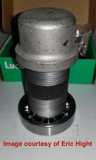
In the below photos are two DIY options for pulling the hub and bearing.
Many parts stores will loan you a timing gear puller, but they are cheap. (The AMPRO T75904 Timing Gear Puller is $16.00 on Amazon.)
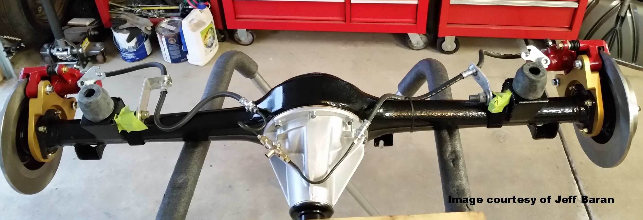
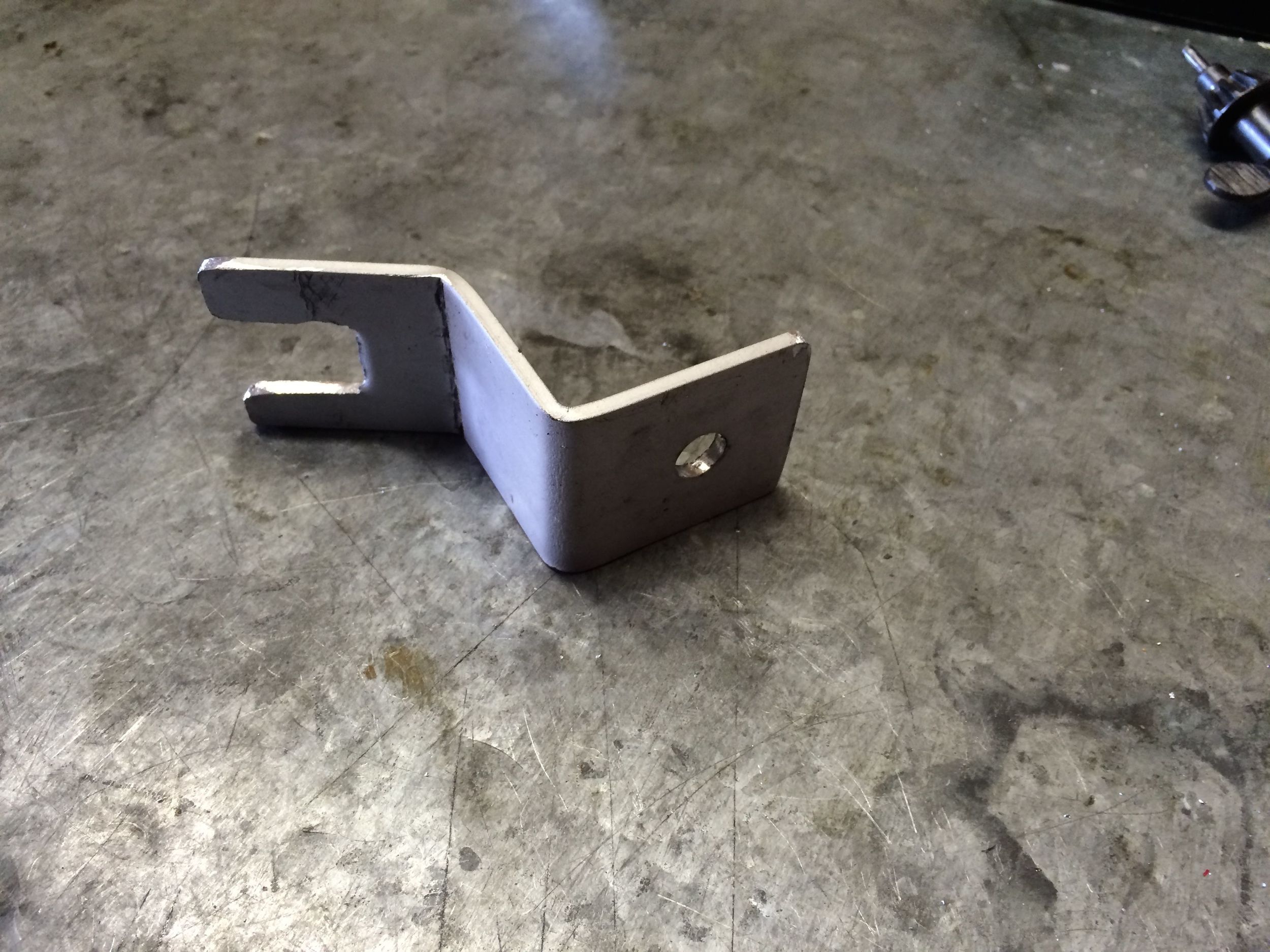
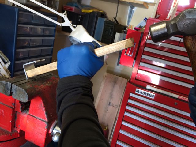
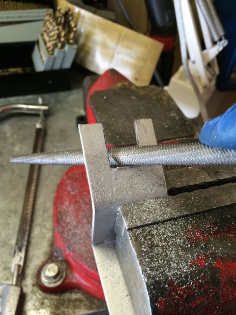
The bolts that thread into the hub are 1/4-28. The first photo shows a piece of 1/8" x 1-1/2" aluminum stock that will be used for 'L' brackets to secure the brake hoses to the axle housing.

The next photo series shows how to use a 3/4" brass plug inside the axle tube for the puller to exert force. It then shows how to use a 3/4" x 5" nipple with fender washers and 3/8"x6" bolt to get the bearing started, after which you can tap it home with a 1-1/2" nipple and cap.


STEP 3 - Disconnect parking brake linkage and steel brake lines behind backing plates. Remove backing plates with wheel cylinders attached.
STEP 4 - Clean the axle housing flange to remove gasket cement, dirt, etc., as the adapter plates must lay perfectly flat on the axle flange's mating surface.
STEP 5 - Bolt on the aluminum adapter plates, using 5/16-24 bolts, washers, and lock nuts, torquing them to 20 ft. lbs.
The bolts need to be 1-1/4" long to accommodate the thickness of the adapter plates and washers. 1-1/2" is fine if you don't mind them sticking out the back a little. You might squeeze by with 1" bolts if your washers are very thin, but you must not defeat the locking function of the nuts by using bolts that are too short and do not extend into the nylon insert or oval portion of the nuts.


STEP 6 - Check your bearings for play, replace the oil seals if necessary, and reinstall the hubs as described in your shop manual. Click the button for tips on reconditioning and updating your hubs and axle housing:
Norm Kerr, author of the webpage accessible through the above button, recommends 140 ft. lbs., which is what was done on the test Midget in the photos. Other mechanics conclude that roughly half that amount is ample.
PART Ii - preparing and mounting the discs
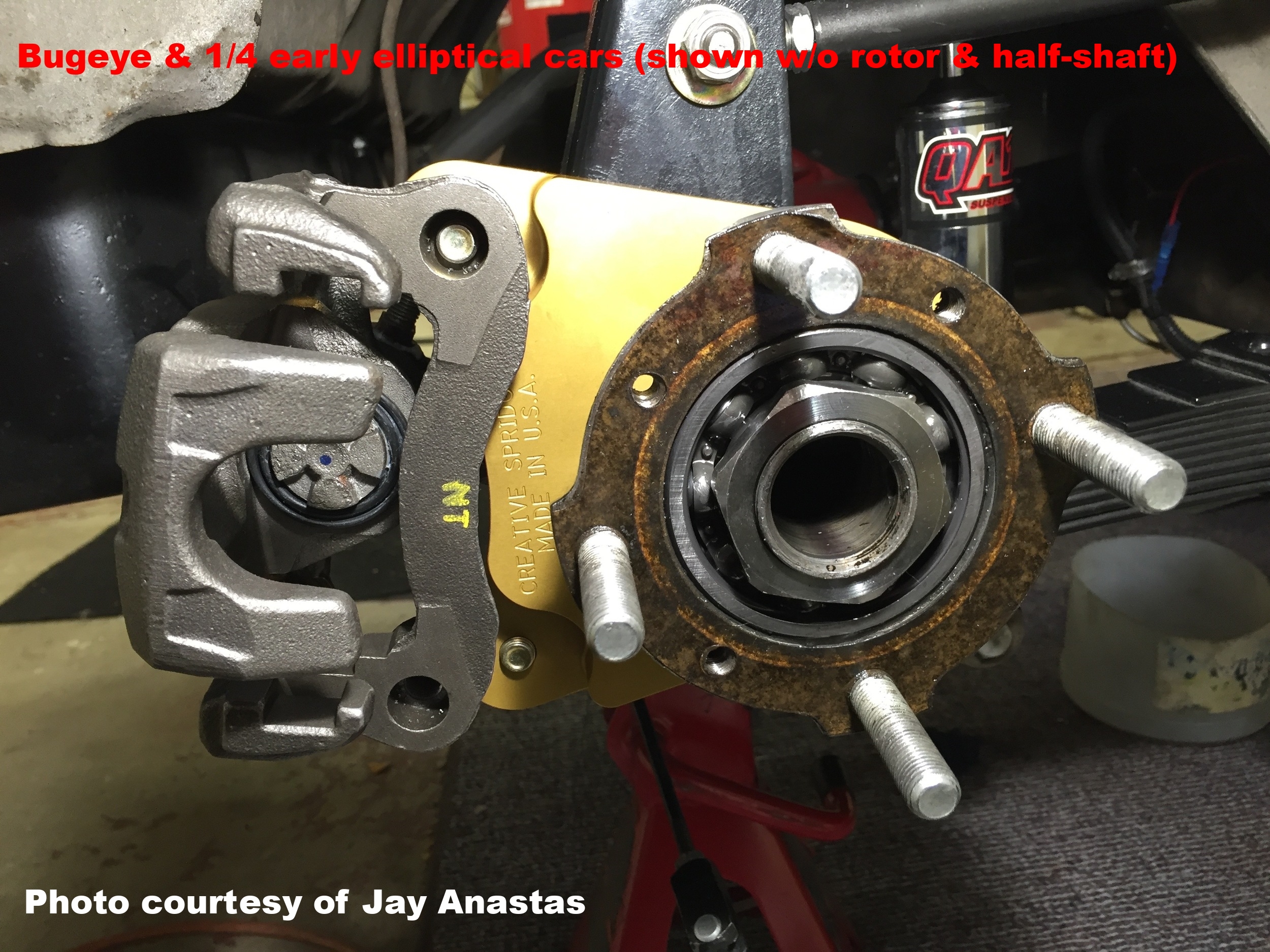
STEP 1 - Enlarge the bores of the rotors using your Dremel or drill motor. This is EASY to do accurately, and is the first of three minor fabrication tasks on 1/2 elliptical spring cars; four on Bugeyes and some--but not necessarily all--early 1/4 elliptical spring cars.
Before you enlarge the central bore of the rotors to achieve 'self centering,' read the following notes on inboard-outboard alignment.
BUGEYES: the Bugeye axle housing requires 2.0mm ~ 2.2mm (.080" ~ .086") spacers or shims between the half-shafts and the rotors. See the parts list. On disc wheel cars ONLY, these shims MUST be in place on the half-shaft before you machine the rotors as described below.
OTHER EARLY 1/4 ELLIPTICAL SPRINGS: some but evidently not all of these cars require spacers.
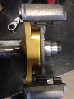
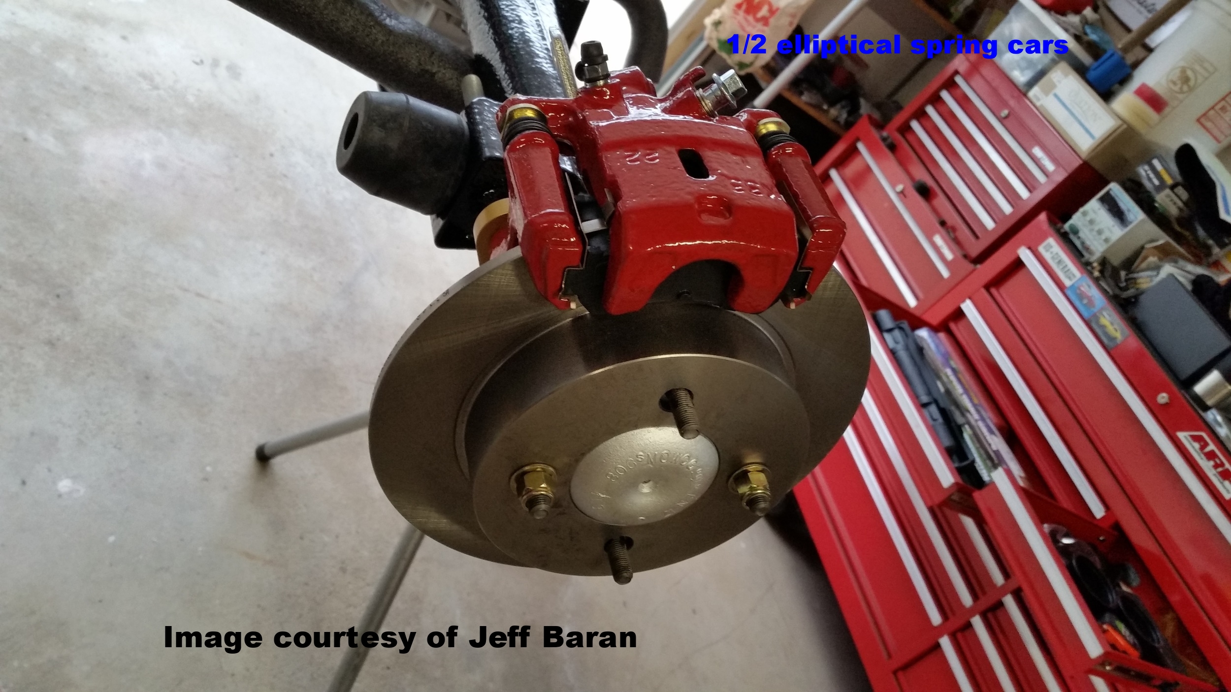
Below are two properly aligned rotors. As discussed above, Bugeyes typically require shims between the half-shafts and rotors. The same is true with some, but not all early 1/4 elliptical spring cars.
This 1/4 elliptical spring car did not require shims behind the rotor, but the owner did put washers between the caliper and adapter bracket:

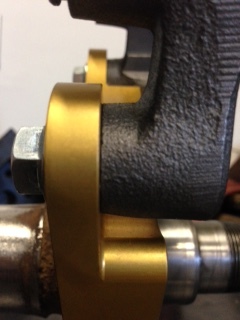
Occasional variations in manufacturing tolerances may reduce clearance on one side of the rotor or the other. All that matters is there should be no contact between the rotor and the caliper's 'floating' guide bracket:

Wire wheel cars are VERY straightforward. Simply enlarge the rotor's central bore by holding the Dremel or drill motor perpendicular to the rotor's surface:

Take your time. Your aim is to enlarge the bore just sufficiently for the rotor to be a slip-fit over this portion of the half-shaft, ideally with no lateral movement:
Cars with disc wheels are only slightly more complex. Enlarge the central bore by alternating between 90 degree and 45 degree passes. The chamfer angle of 45 degrees is maintained by laying the Dremel or drill motor body against the shoulder of the well in the rotor, as you will see in the video below.
The central bore should just slip over the bulge so the rotor lays flat on the flange without any lateral slop. A tiny audible 'clink' is acceptable, but try to avoid visible lateral movement if at all possible.

Below is a video. Rest the rotor in the jaws of a 6" or larger vise padded with a towel or thick rag for smooth turning. If you do not have a vise, you can use two pieces of lumber to elevate the 'hat' of the rotor above the workbench.
If you have heavy-duty or racing half-shafts, they may not lend themselves to the self-centering method described above. In this case, you will need to have a machine shop redrill the rotors to the Spridget stock PCD, as pictured here:
STEP 2 - Reinstall the half shafts using new paper gaskets and 'O' rings, and do not forget the countersunk screws that hold the half shafts onto the hubs. I use a thin film of non-hardening gasket sealer on both sides of the paper gaskets, but that is a personal preference.
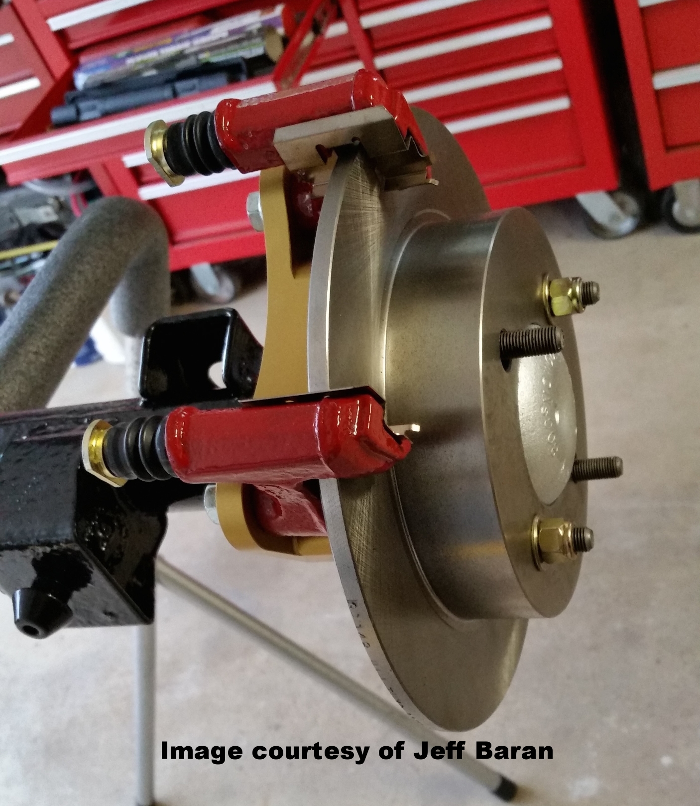
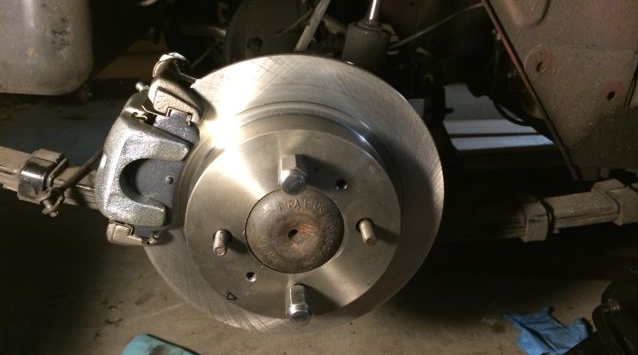
STEP 3 - Slip the rotors onto the studs.
On cars with disc wheels, use a couple of lug nuts to hold them in place temporarily until you mount the wheels, which will pin the rotors against the hubs once the lug nuts are torqued:

On cars with wire wheels, reinstall the tab washers (Moss Motors 181-915) and nuts as you would have done if replacing the drums, making sure to bend the tab washers up to retain the nuts and keep the rotors in place. The below image does not yet have the tab washers in place:

PART Iii - calipers and pads
STEP 1 - If you opted for used calipers, clean them up and consider installing new seals. You do not have to fully rebuild the calipers, and some 'pre-loved car dismantling emporiums' (a term suggested by a respected United Kingdom consultant) will exchange leaking calipers.
If not, consider replacing the piston seal and dust boot, as well as the seal on the parking brake cam bolt. These are simple to replace. Below is a video on rebuilding a similar Nissan rear brake caliper.
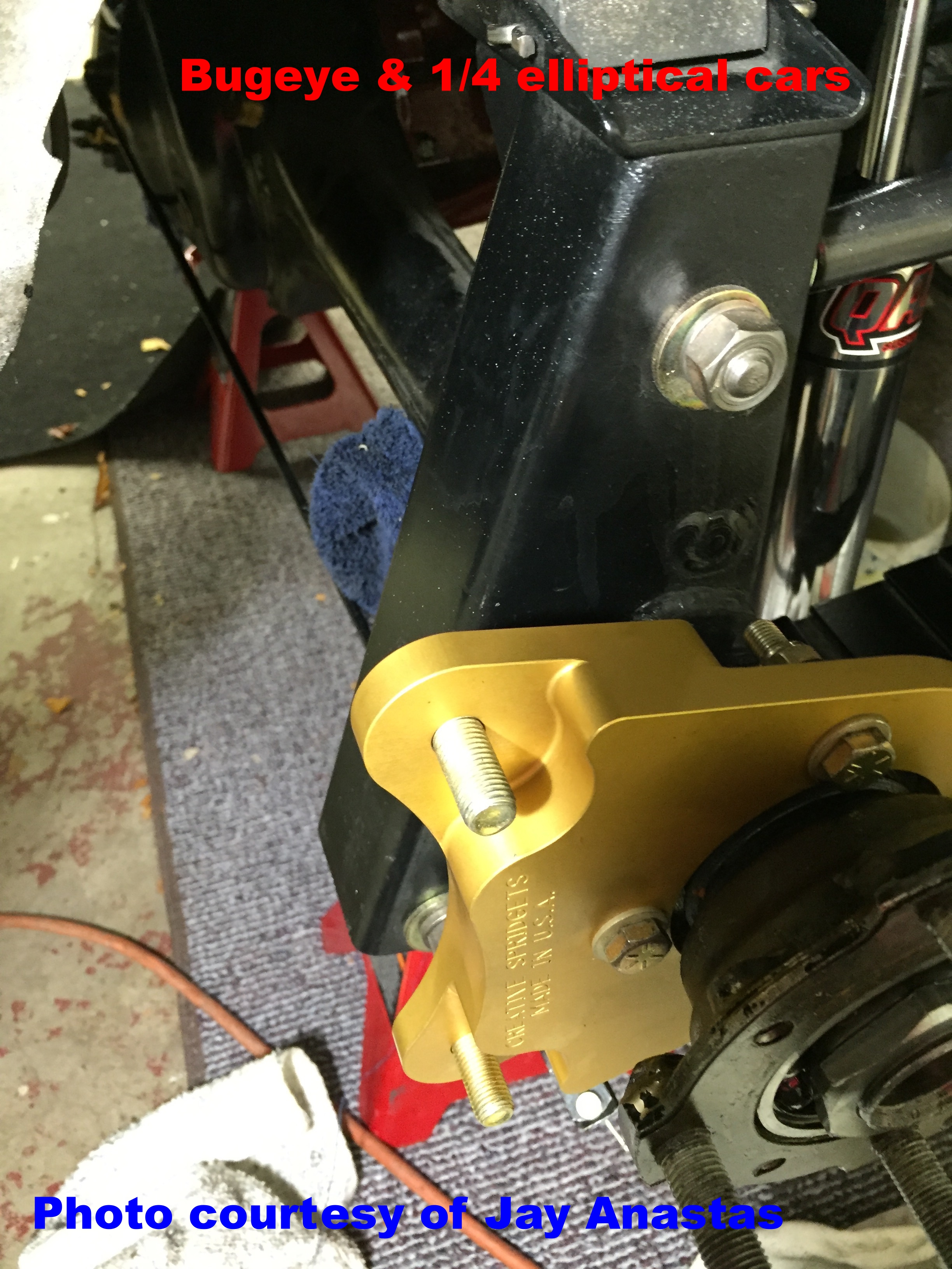
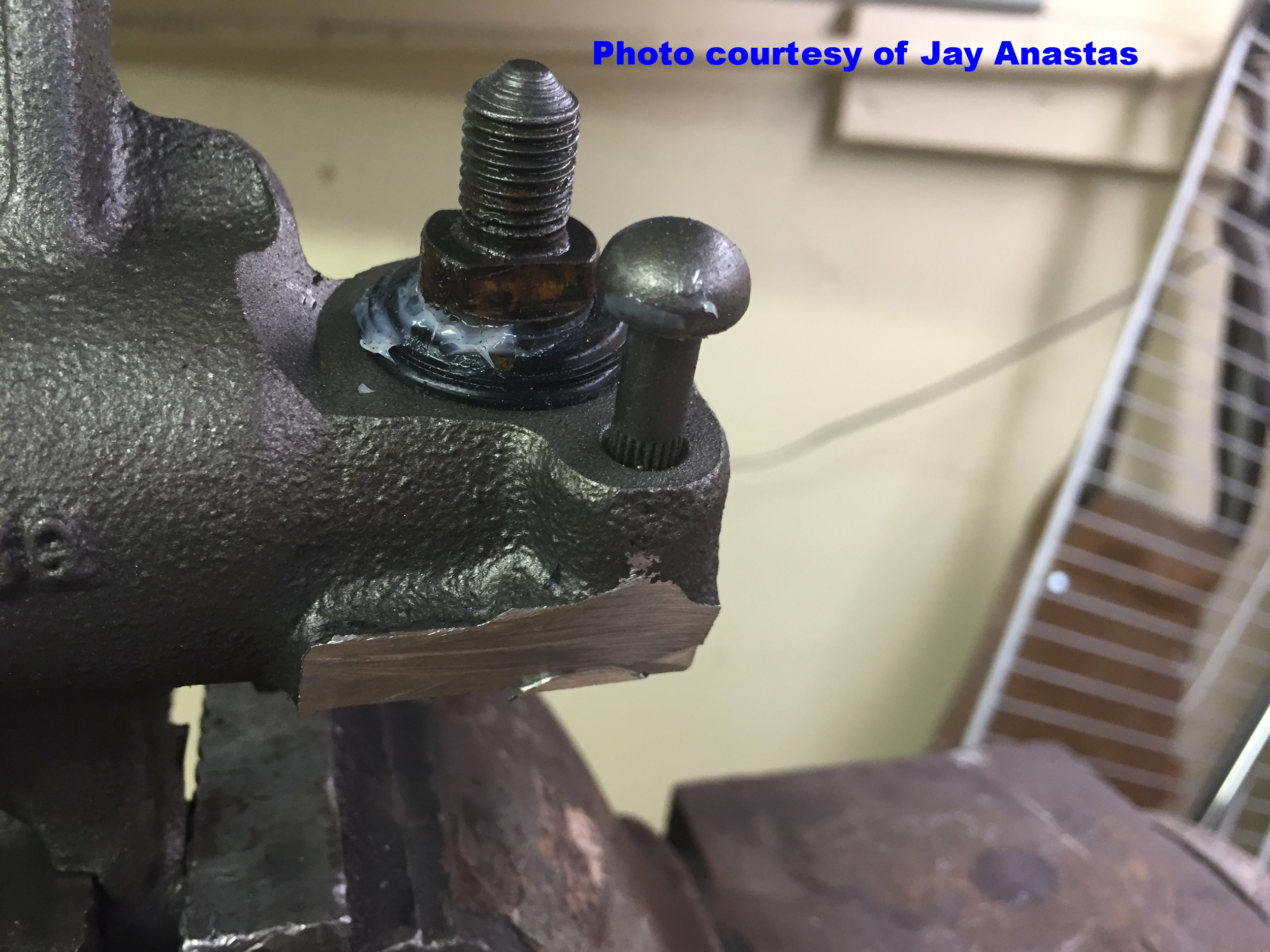
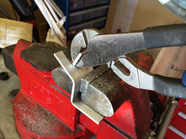
STEP 1.5 - for Bugeye and early 1/4 elliptical spring cars only. For cars with the 1/4 elliptical spring suspension, you must cut off the unused cable bracket from the Sentra calipers with a hacksaw, as pictured here. This provides clearance for the upright welded to the rear of the axle housing on these cars:

STEP 2 - If you did not rebuild your calipers, remove the return springs, nuts, and lock washers from the Sentra caliper cam bolts, and remove the parking brake toggle levers. Pay attention to how the tab rests against the stop to simplify reassembly later on.
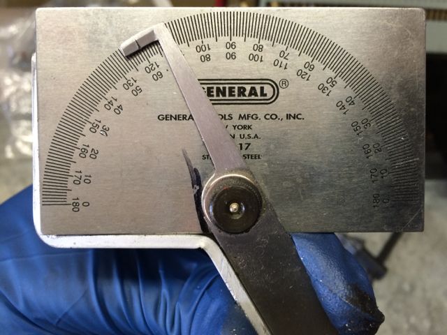
STEP 3 - Now drill a 1/4" hole in each lever like this:

The location of the holes is not critical, but you should follow two guidelines. First, keep the edge of the hole far away enough from the edge to avoid wearing through. Second, with the former caution in mind, drill as far away from the cam bolt as you can, to increase leverage.
STEP 4 - Bolt on the toggle levers using the lock nuts, but note that you will not need the return springs. The Spridget cable system and the calipers' natural rebound effect are sufficient to retract the pads. You will have to turn the cam bolts slightly with an 11mm spanner slid partway onto the cam bolt, to allow the toggle levers to clear the stop pin and fit down onto the keyed portion of the cam bolt. This is a little tricky, as they want to rotate back before you can slip the levers on. Be patient and you will get them on.
STEP 5 - Bolt the Sentra caliper guide brackets onto the aluminum adapters using the OEM Sentra bolts and lock washers you harvested with the calipers, or use Grade 8 M10-1.25 bolts. Torque them to 30~32 ft. lbs.
STEP 5.1 - Address fitment issues related to manufacturing variances (if any). Here are three problems that users have encountered arising from the manufacture of either the Spridget axle housing or the Nissan parts.
Problem (a): If you bought rebuilt calipers, the factory may overdo it on the anti-corrosion coating, making it hard to start the bolts.
Solution: Run an M10-1.25 tap through the threads using plenty of oil, and things will go a lot easier. However, this may not be a problem, and simply running the bolts through a couple of times could be sufficient.
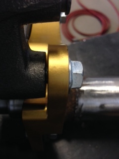
Problem (b): Charlie Durning has noted that manufacuring differences in the axle's backing plate flange may reduce rotor-to-bracket clearance.
Solution: If the rotor is too close to the floating bracket on the inboard side, place shim washers between the hub and rotor. (Note that this is the same measure taken on Bugeye Sprites above in Part II, Step 1.) If clearance on the outboard side is the problem, place shim washers between the aluminum adapter and the Sentra 'floating' caliper bracket.
**If you have a wire wheel car, do not forget to affix the nuts retaining the rotor by bending up the tab washers.
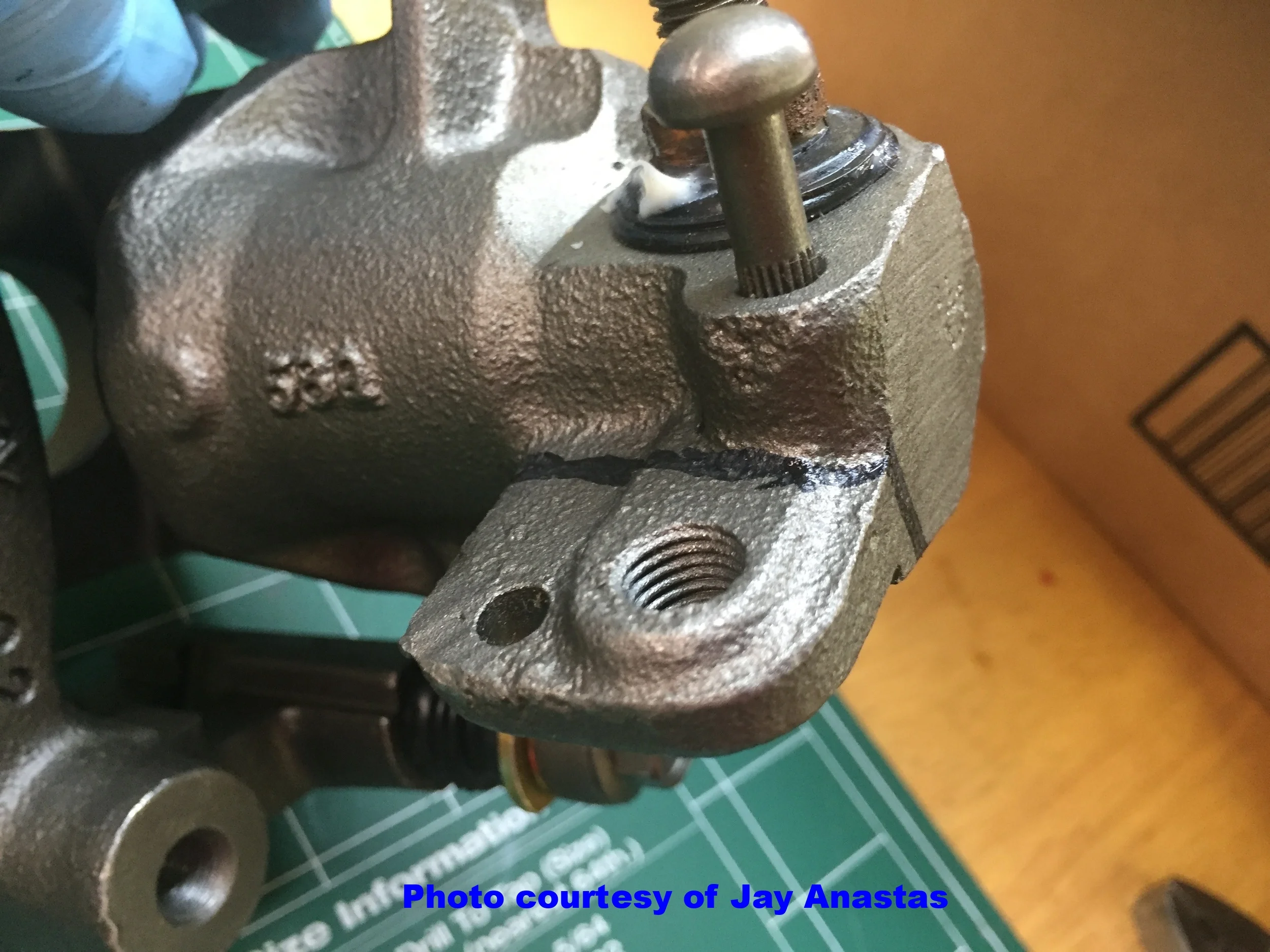
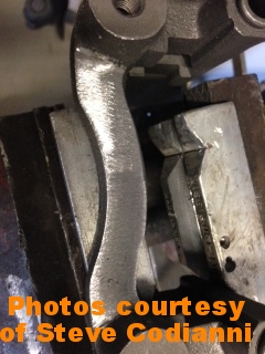
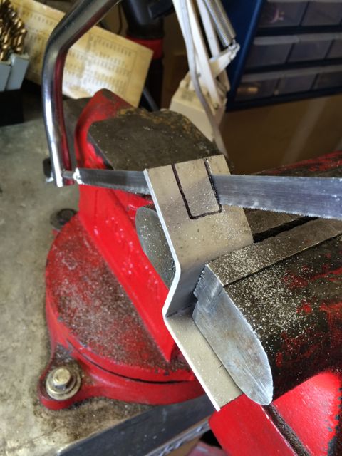
Problem (c): Steve Codianni encountered a casting whose identifying letters contacted the adapters:
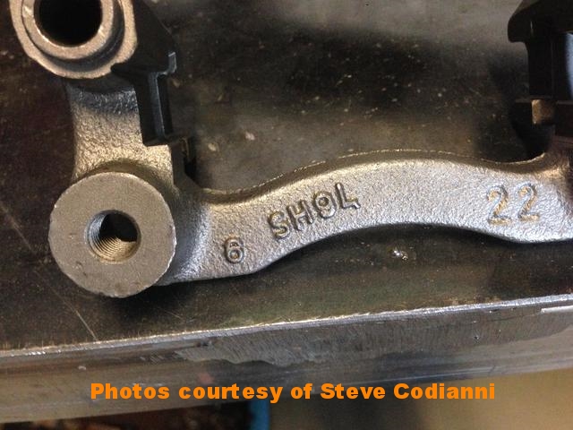

Solution: Simply grind down the raised lettering as shown:
STEP 6 - Install the pads.
Clean the bedding surfaces of the rotors thoroughly on both the inboard and outboard sides with brake cleaning solvent and paper towels, until absolutely no grease appears on the towel.
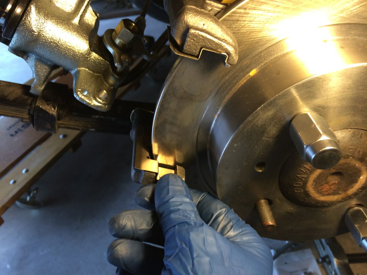
Then position the brake pads, making sure you have the brake hardware (thin metal guide plates) in place on the Sentra floating brackets and calipers:
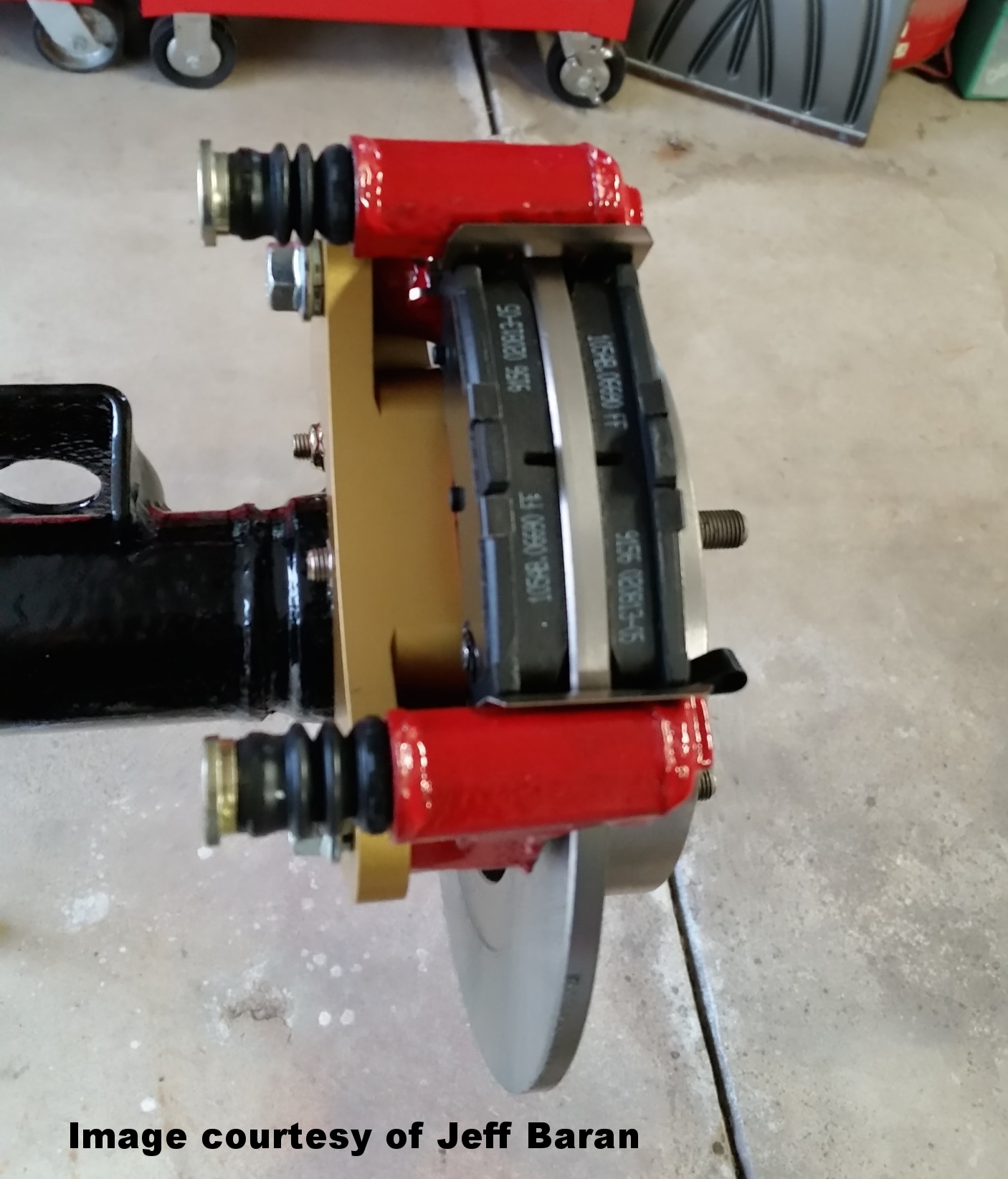
STEP 7 - Install the calipers.

As with the guide brackets, make sure you have the brake hardware (thin metal guide plate) in place in each caliper, as shown in the next photo. Then slip the calipers into place and torque the guide pin bolts to 23 ft. lbs.

Autozone has a kit they will lend you to do this, but I bought an excellent kit from Harbor Freight Tools for $45 that works on every car known to humankind.
Take a moment to step back and admire your work. The more difficult bits are done!


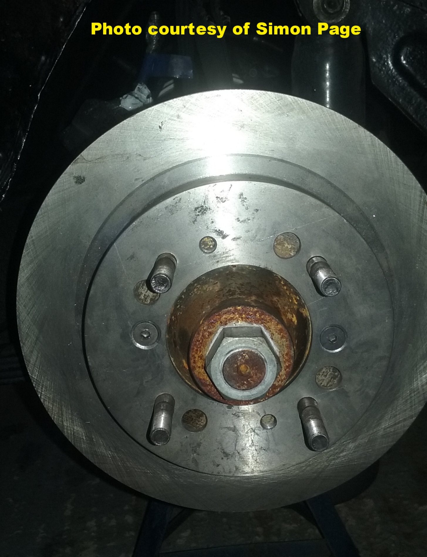
Unlike the rotors, the wheels are centered by the tapered portion of the lug nuts, shown here:

So, if your Rostyle wheels are out of round, bent, or sloppily manufactured, they may contact the calipers here when you slip on the wheels:

However, do not get excited or attempt to fix the problem by filing down the high points on the wheel before you tighten down the lug nuts in the proper sequence to center the wheel, which will produce sufficient clearance.
You should also eliminate a bent or out-of-round wheel before giving these high spots a few licks with a file. Try your spare or another mounted wheel. If you resort to filing the high spots and live in a climate where the roads are salted in winter, put a dab of paint on the bare metal to avoid rust.
Once you have tightened the lug nuts, use a flashlight and look inside the Rostyle wheel to ensure clearance--which will appear very close. Again, this is normal and no cause for concern.
PART Iv - brake lines
You have two choices with the brakes lines:
Replace the original Spridget steel lines with stock Sentra hoses connected to short adapter lines and fittings, as shown in the next few steps.
Buy the 3-AN banjo fittings, tube nuts, and sleeves shown on the parts list to connect the stock Spridget steel lines directly to the calipers.
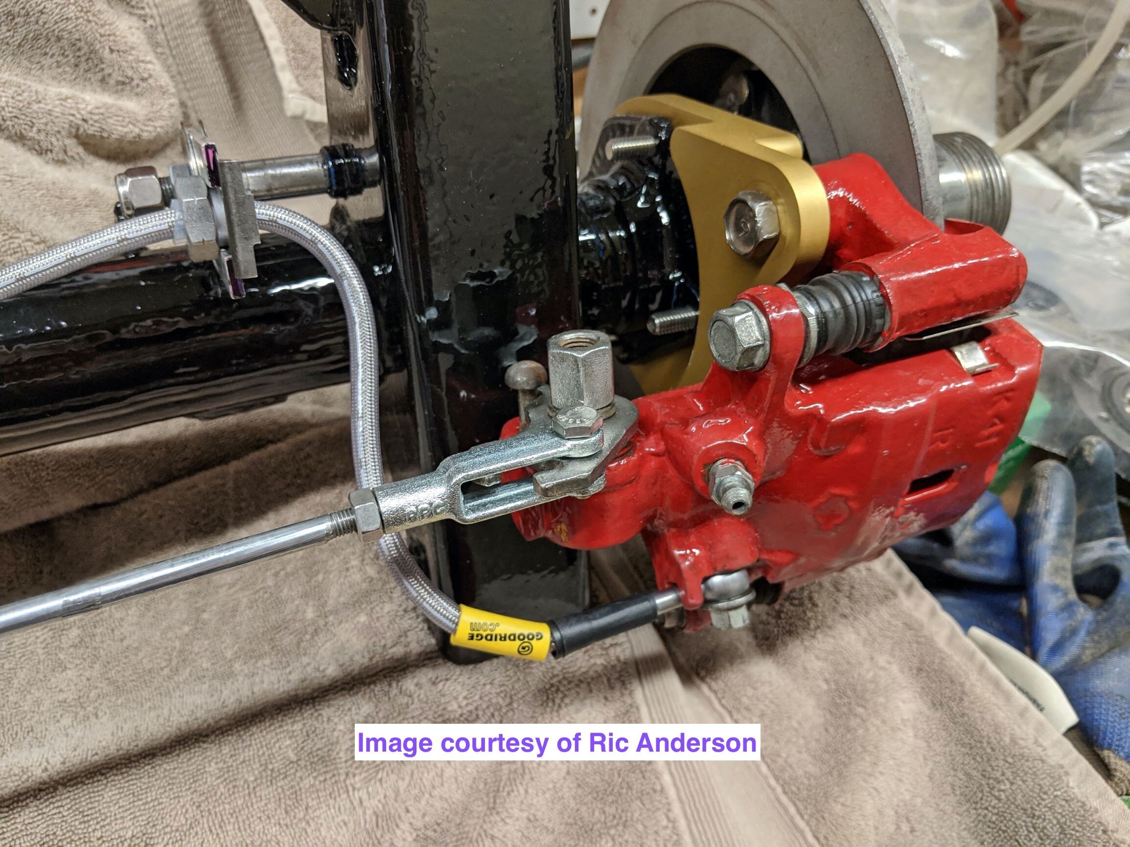
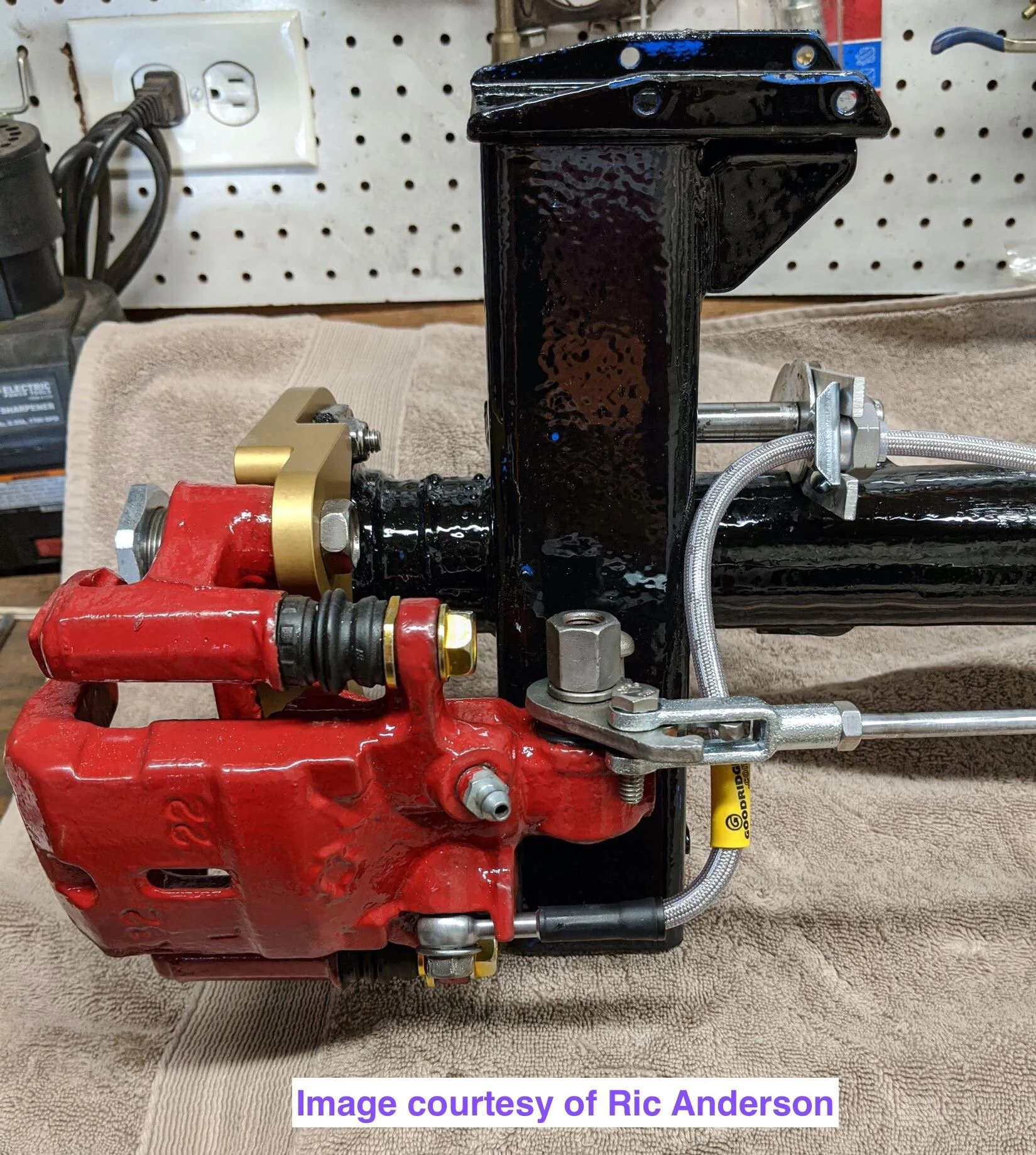
Both options have pros and cons. Using the flexible hoses makes replacing pads and servicing the hubs and so forth easier, since you can just leave the caliper connected to the hydraulic system and the parking brake rod, pivot it on the toggle lever (which acts like a hinge), and rest it on the leaf spring as shown below.

On the other hand, the 3-AN option eliminates the flexible hoses, 8" adapter brake lines, and the British-to-SAE thread adapters, and uses the same fittings and flaring tool used to install the proportioning valve. Also, you do not have to bend the adapter lines, or make 'L' brackets to affix the brake hoses (though those tasks only take about an hour).
However, you must either be very careful to avoid damaging the Spridget steel lines or disconnect them each time you wish to change pads or service the hubs. This option may be more attractive to autocross racers or other owners who don't mind bleeding the brakes more frequently.
If you want to use the Sentra hose setup and wish to add a proportioning valve, note that the listed valve comes with 3/8-24 inverted flare female fittings. So, you can install 3/8-24 inverted flare male fittings on the Spridget 3/16" rear-circuit brake line instead of 3-AN fittings, if you have the standard inverted flare tool.
The following procedure is for the Sentra hoses and 8" Poly-Armor adapter brake lines, which produces a durable, easily-serviced configuration resembling that found on most modern production vehicles.
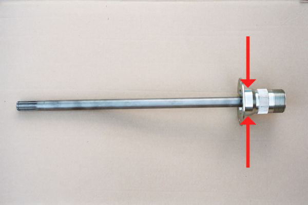
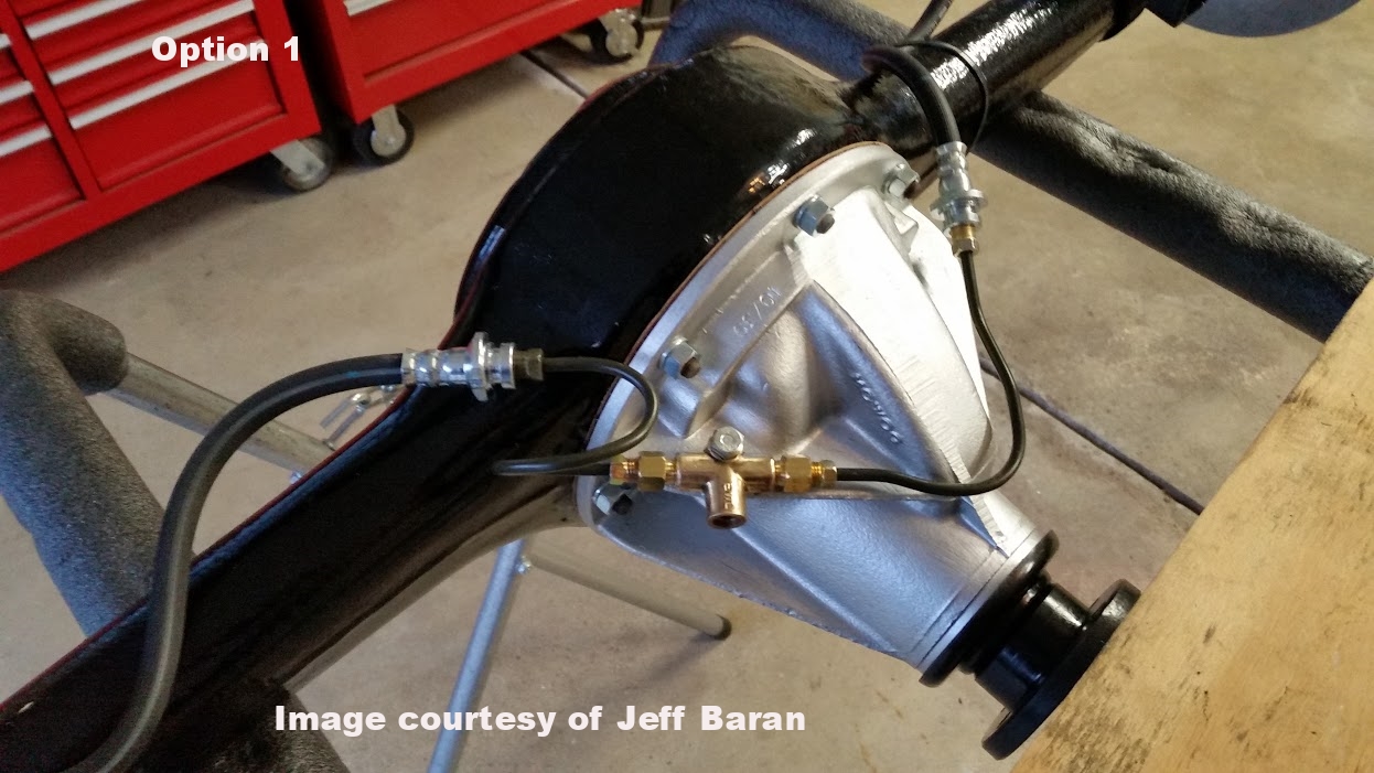
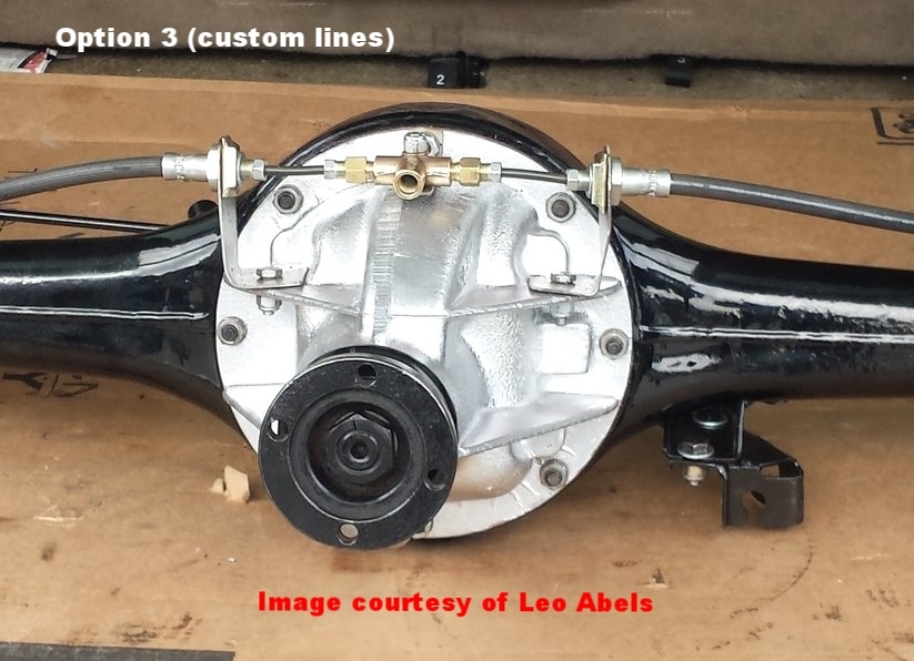
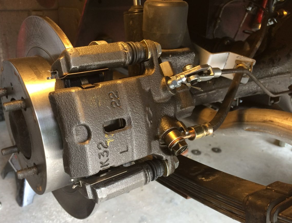
STEP 1 - Unscrew the OEM steel brake lines from the brass tee bolted to the differential, pictured here. You must loosen the bolt fastening the brass tee to the differential in order to get your brake fitting wrench around the brake line fittings. Replace the OEM steel brake lines with the brass British-to-USA thread adapters and seat them tightly.


Here is how the brake line components will fit together (though the steel adapter line is not yet formed as discussed below). The British-to-USA thread adapters used in the above step are shown on the right.
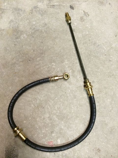
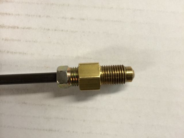
The parts list has both NAPA part numbers for the 8" Poly-Armour adapting brake line, one of which has 3/8-24 at both ends. The 3/8-24 threads will insert in the M10x1.0 female socket of the hose, but will leak or even strip when tightened securely, so make sure you get this right.
STEP 2 - Using an appropriately sized tubing bender such as that listed in the tool list, form the Poly-Armour adapting 8" brake lines as shown below. The Sentra hoses are in place in this photo to show how they are ultimately positioned, but they are not installed for a few more moments.
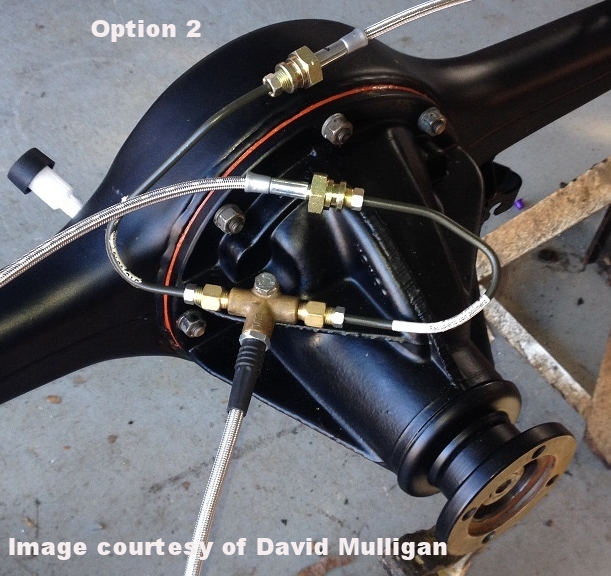
Update January 10, 2016 - Our friend David found the above braided stainless hoses, that have now been added to the parts list.
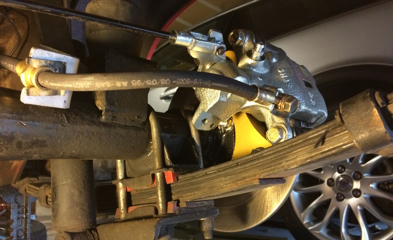
STEP 3 - Connect the 'banjo' fittings on the caliper ends of the Sentra hoses to the calipers finger tight. Extend the hoses to where they will connect with the adapter lines. If they are difficult to maneuver into place, swap the hoses (the banjo fittings are crimped on at an angle specific to each side). Now, using copper washers to 'sandwich' each of the banjo fittings, torque the fittings onto the calipers at 12-14 ft. lbs.
STEP 4 - Securely tighten the female ends of the hoses where they connect with the M10x1.0 ends of the adapting brake lines, and tighten the other end to the British threaded adapters at the brass 'T.'
You must hold the metal fitting on the end of the rubber hose with an adjustable wrench, water pump pliers, or large vise grip, as on the Sentra there is a keyed flange welded to the car that keeps the hoses from turning. You will need a 10mm wrench for the metric end of the Poly-Armor adapting steel line.
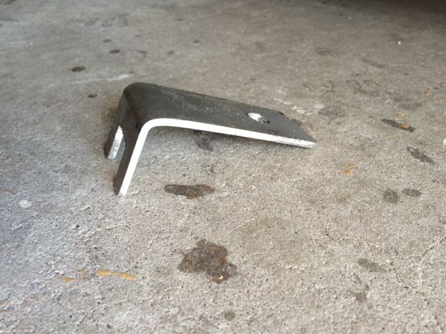
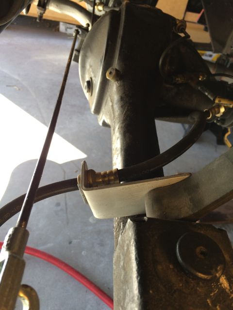
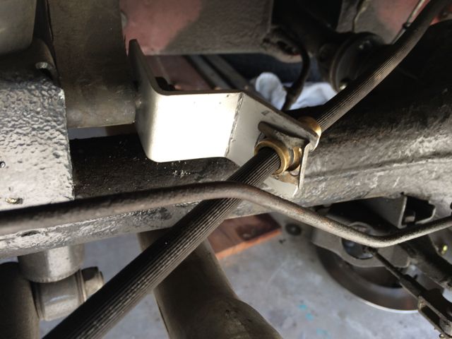
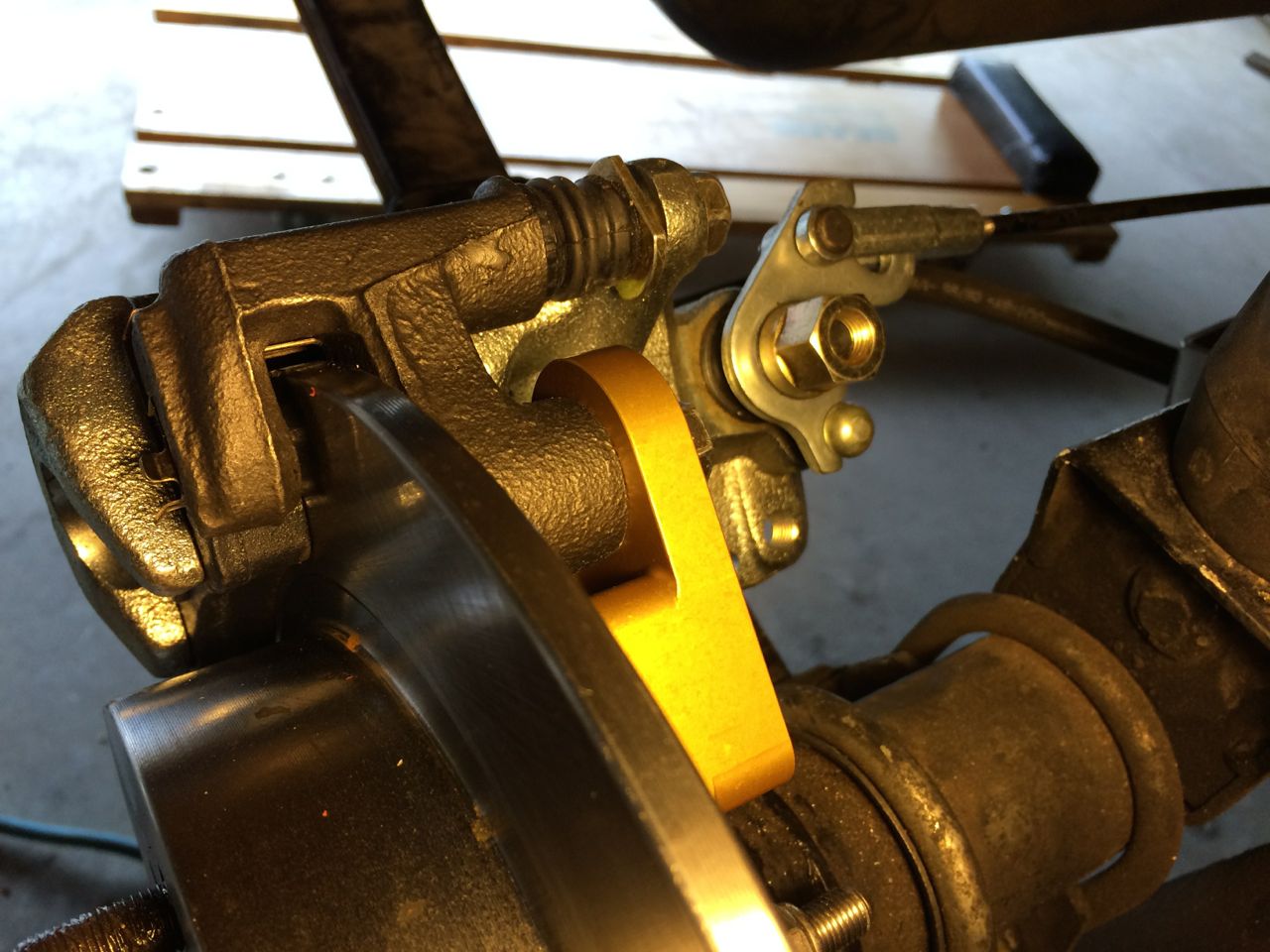
STEP 5 - Secure the Sentra hoses to the axle housing and away from exhaust pipe. You can make either L-shaped brackets or straight brackets with the 1/8"x1-1/2" aluminum stock, then secure the fittings with retainer clips you harvested at the pre-loved auto parts emporium, or from an auto parts store or Nissan dealer. Below are examples of each style:
L-shaped brackets:
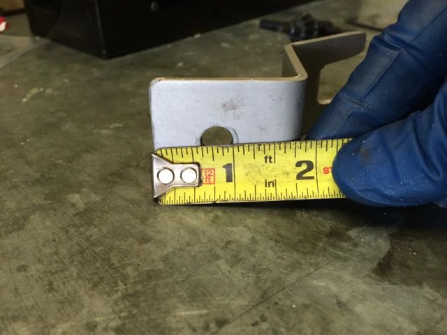
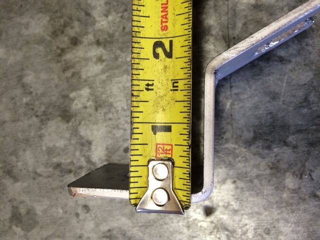
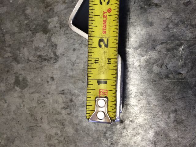
The brackets shown here took 30 minutes to make, and 10 minutes to install:

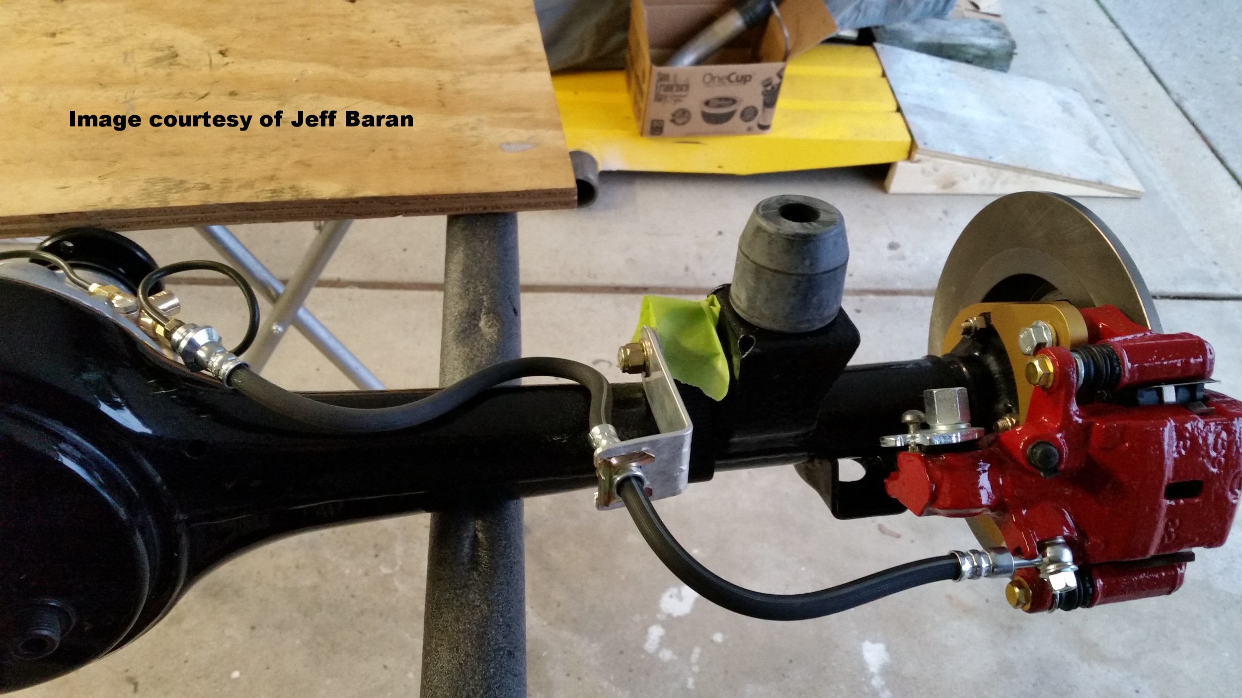
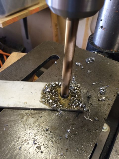
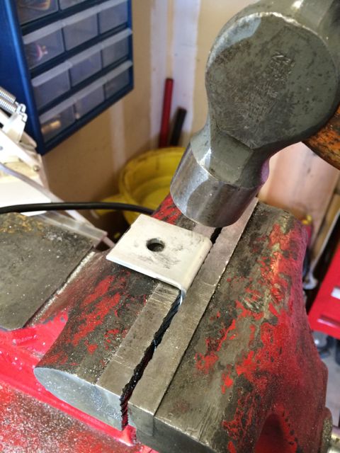
I give measurements for the L/H bracket, but you should experiment with the length of the 'L'-shaped R/H bracket. The length of the R/H bracket is dependent on how you bend up the Poly-Armour adapter line and not at all critical. The 3/8" bolt hole center is 3/4" from the end on both pieces.
Here is a photo sequence showing the fabrication process, which takes about 15 minutes per bracket.

Straight brackets:
Here is an example of straight brackets, which the owner tells us allowed him to avoid the bends in the short brake rod discussed in the following section:
PART V - parking brake linkage
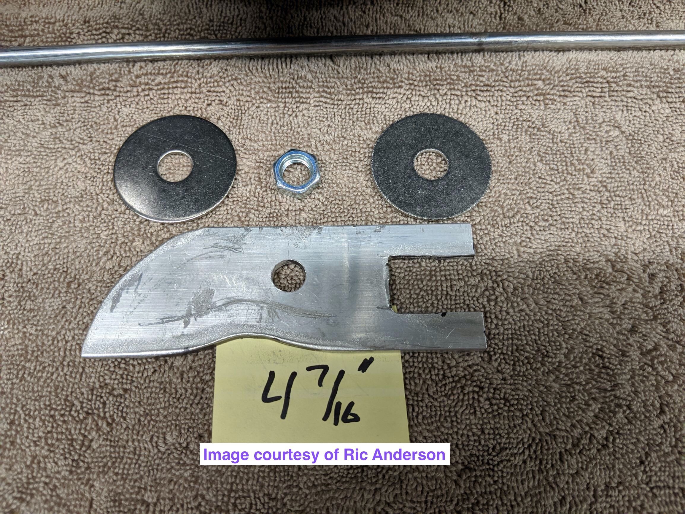
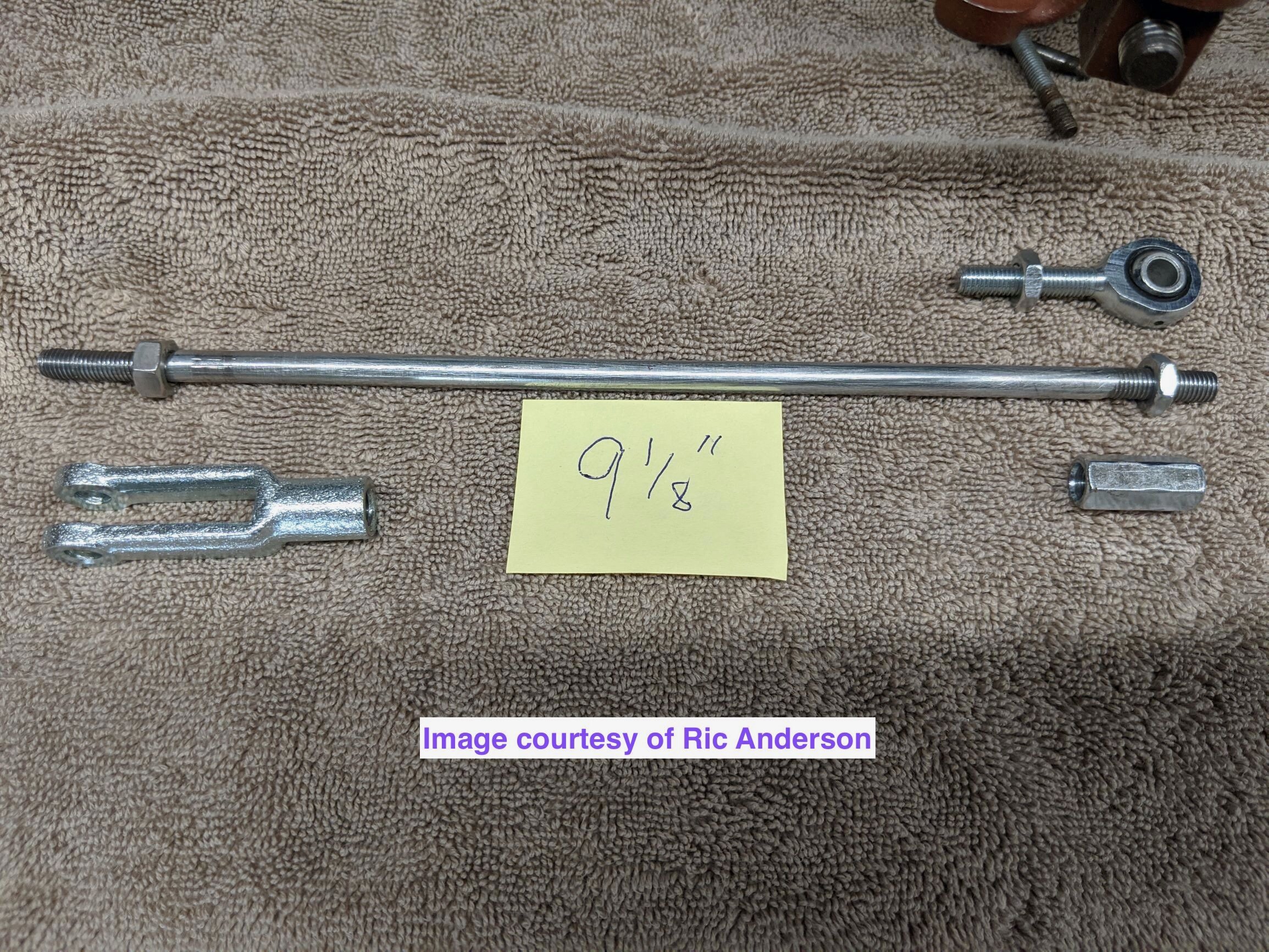
For the conversion, you can buy adjustable rods from Moss Motors for $45, or make your own using 1/4" mild steel rod and two additional yoke ends from the parts list for around half that amount. Simply follow the steps in this procedure to make them--but remember to leave enough length at the inboard end to thread the rod into the yoke (the original yoke is brazed on or cast as a unipart).
STEP 1 - Follow this step if you are modifying OEM-style brake rods (if not, skip this step and go on to Step 2):
First, cut 3.5" from the outboard (yoke) end of the long braking rod, and 4.25" from the outboard (yoke) end of the short rod.
Second, thread the last 1.25" or so with the die in the parts list below.
Do not be intimidated by using a die if this is your first time. It is easy to do:
Start the die with your fingers, keeping it perpendicular to the brake rod, and the moment it bites add some motor oil (or whatever kind you have handy).
Use a die handle or adjustable wrench to proceed, backing off a half-turn or so whenever the resistance increases and adding oil.
When you have cut 1.25" of threads, leave the die well down on the threads, and use a file or sandpaper to clean up the rod end.
Finally, back the die off to reopen the threads and establish a clean starting place for the yoke. Add a lock nut if you like.
Third, make two bends in the short rod at about 1/3 and 2/3 along the length to approximate this shape (no bends are needed in the long rod). The bends prevent the rod from chafing the brake hose—but see the note about the need for these bends in the following section.

STEP 2 - Fashion your own rods.
You can save roughly 50% by making your own rods rather than buying generic adjustable rods from Moss, et al., and you end up with a cleaner, more elegant-looking setup.
Here are photos with measurements from a Bugeye owner who went this route. Note that he uses small Heim joints at one end to build in some flexibility—and likely durability—in the operation of the mechanism:

*Note: the above owner did not need the bend in the short rod, because his brake hose brackets created sufficient clearance:

STEP 3 - Reattach the new yoke ends to the toggle levers and the original ends of the brake rods to the central pivot, using the original clevis pins and new cotter pins or new pins if you like.
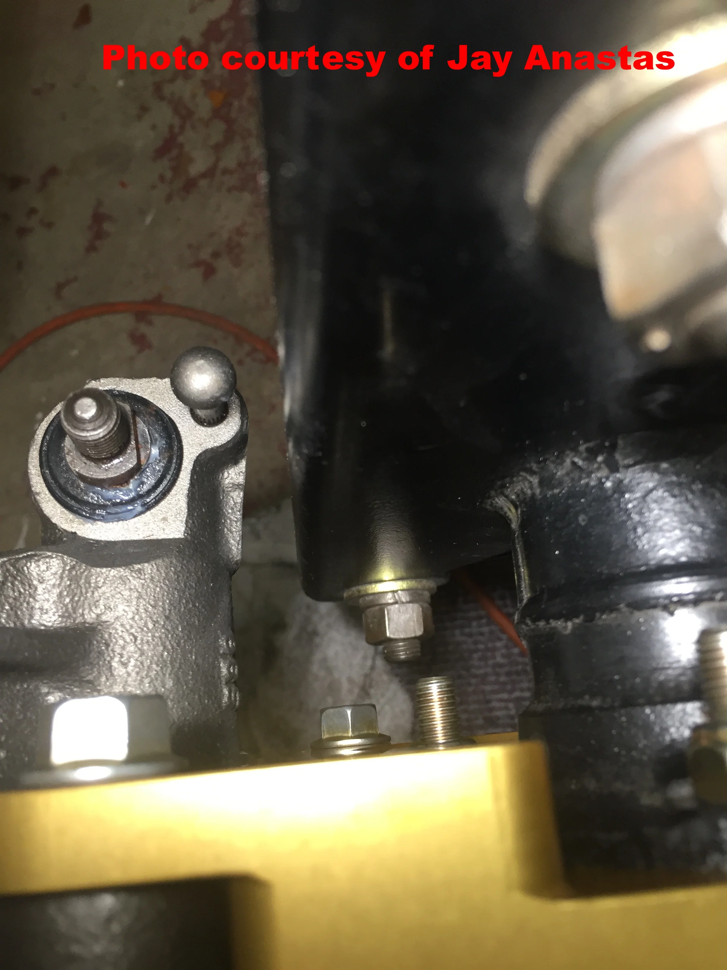
The toggle lever travel on the Sentra/200SX calipers is quite short, and it closely approximates the range of the OEM Spridget drum setup.
The brake hose looks like it is close to the exhaust pipe in the photo, but that is an optical illusion. There is plenty of clearance.
Step 4 (optional) - Add a compensator to reduce handbrake lever travel
As shown below, you can add a simple compensator that will make engagement of the hand brake more positive, and reduce travel of the lever in the bargain.
The effort required will be slightly increased, but this is easily adjusted by altering the length of the plates bolted onto the OEM pivot:

PART VI - PROPORTIONING VALVE and bleeding system
With original Lockheed discs up front, mounting rear disc brakes will produce a definite rear-wheel bias. If you have a 'big brake' conversion up front, the rear bias may be less pronounced or even non-existent. Either way, a proportioning valve is necessary to avoid rear-wheel lockup and to fine-tune and maximize the benefit of four-wheel discs.
If you run out of time and need to drive the car to work, a valve is easily added after performing the rest of the conversion, but use extreme caution as the rear wheels may lock up in a panic stop. Click here for an information sheet on the valve in the photos.
The valve must be spliced into your rear brake line, and is done at a different location depending on whether you have a late-model, dual-circuit master cylinder, or an early-model, single-circuit master cylinder.
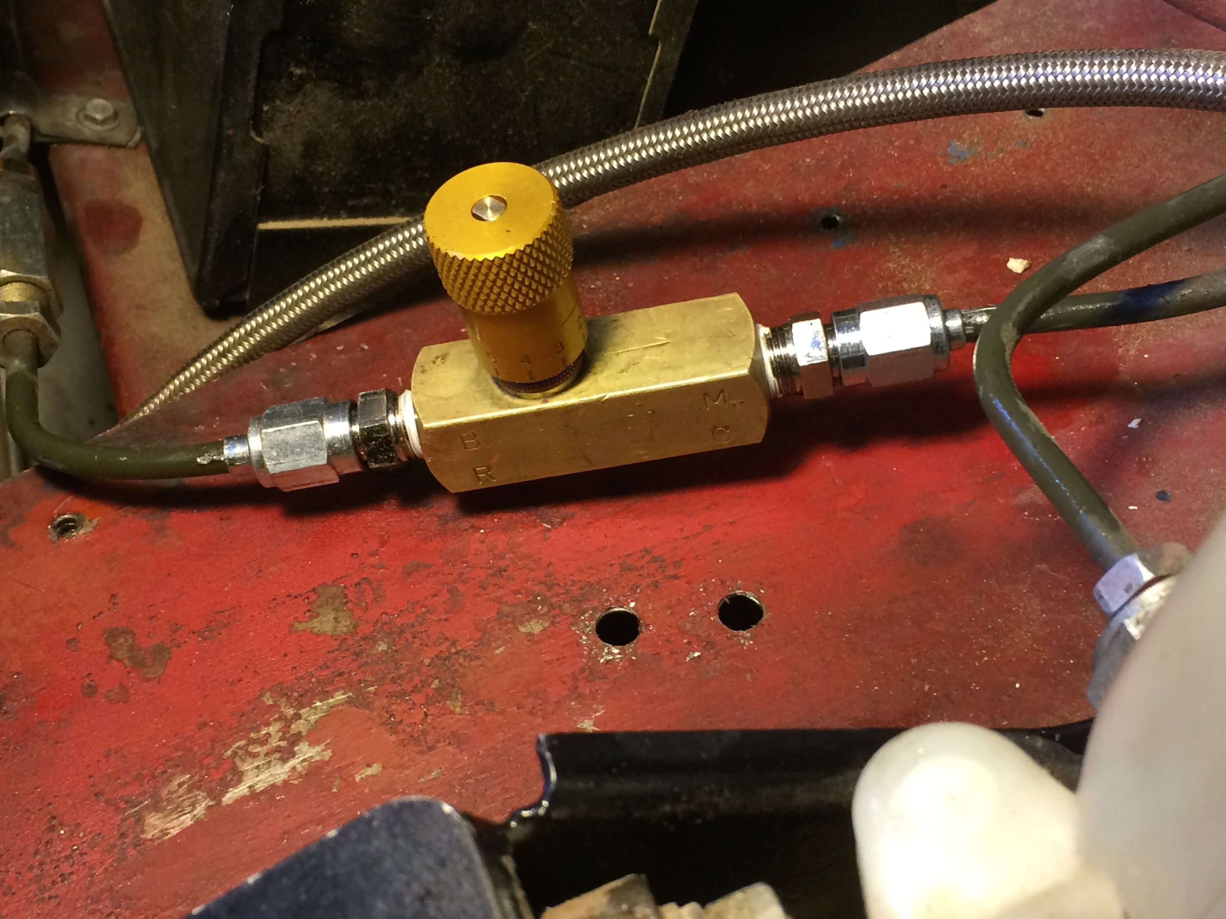
On later cars with a dual-circuit master cylinder, the proportioning valve may be mounted adjacent to the master cylinder, as depicted here:

The holes are from the old Wilwood valve, which was larger and required a bracket. The Deltrol valve pictured is very small and a bracket is optional.
The recommended Deltrol proportioning valve pictured above and in the parts list does not come with fittings. You will need 1/8" NPT fittings to attach brake lines, available at any auto parts store, and most hardware stores. You can use standard inverted flare male fittings rather than 3-AN fittings pictured here, if you already have the corresponding inverted flaring tool.
The valve is marked 'MC' at one end, which is the input from the master cylinder, and 'BR' at the other, to attach to the brake line going to the rear brakes.
This photo shows the brake line union used with a single-circuit master cylinder, located inside the R/H fender or wing just aft of the lever shock (or upper swing arm if you have converted to telescoping shocks). Splice into the rear brake line, which extends down under the body pan toward the rear axle:

STEP 1 - Determine where you want to fit your proportioning valve, then mark the lines to allow sufficient room for the valve and fittings.
STEP 2 - Remove the line or gently pull it away from the frame or body and, using an appropriate tubing cutter, sever the line and clean up the ends.
STEP 3 - Refer to this procedure for making 37-degree flares, and install 3-AN fittings (unless you are using 3/8-24 inverted flares):
STEP 4 - Screw the 1/8-27 NPT to 3-AN adapters into the proportioning valve using teflon tape (unless using 3/8-24 inverted flares).
STEP 5 - Affix the valve to the lines as pictured here:
STEP 6 - Screw out the Deltrol valve's knob fully before bleeding the brakes. When finished, screw it in gradually using the increments marked on the knob until the rear brakes lock up just after the front brakes.
There is a set screw in the knob to lock in your desired setting.
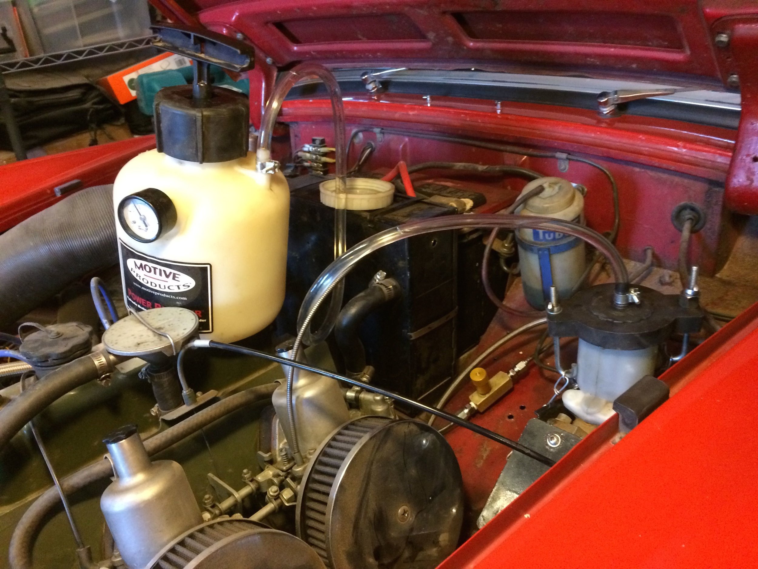

One-man bleeding is a snap with a power bleeder, vinyl tubing, and a jar.
Once the brakes are bled, it is time to bed in the new pads as usual. If you are unfamiliar with the bedding-in process click this button:
Finally, adjust the parking brake cable per your shop manual. The parking brake holds at least as well as the drum setup, but we recommend that you leave the car in gear as well.