
Installing a Volkswagen Rabbit Dual-Pass Crossflow Radiator in the Austin Healey Sprite or MG Midget
The Abingdon factory equipped early model Spridgets with a teensy radiator that was barely adequate to cool the larger 1275cc A-series engine on the cool, misty isle where it was designed. But stop-and-go driving in the American Southwest or south of the Mason-Dixon Line, especially if immediately following an extended jaunt on the highway, quickly reveals the shortcomings of the original design.
While switching to an electric fan is better than the original, belt-driven propeller, what the Spridget really needs is better radiator.
This conversion uses a dual-pass, crossflow aluminum radiator from a 1979 Volkswagen Rabbit. Designed for the Rabbit’s 1500cc 70 h.p. overhead cam engine, this radiator is more than adequate for even hot-rodded A-series power plants when fitted with dual, low-profile electric fans. Best of all, the Rabbit radiator can be had for under $100 online or at your local auto parts outlet, and it has an electronic fan switch mounted in the left-hand tank—the midpoint of the coolant’s run through the aluminum core.
Straightforward modifications to the Spridget’s radiator supports are required, together with fabrication of simple mounts made with inexpensive aluminum stock available at your local home improvement store.
You will need the following parts and materials:
Spectra Premium CU633 radiator (or equivalent) for 1979 VW Rabbit;
Beck Arnley 201-1545 (or equivalent) electronic fan switch with fiber gasket - recommended activation point is 180 F. but cooler and hotter versions are available;
2 Pcs. - Gates 22271 (or equivalent) 1.25” lower radiator hose for 2000 Toyota Camry;
1 Pc. Dayco C71519 1.25” radiator hose for 1993-95 Buick LeSabre or Park Avenue, 1991-95 Oldsmobile 88 or 98, 1994 Pontiac Bonneville or 1992-94 Chevy Lumina APV;
1 Pc. - HPS AJ600-125 6061 T6 Aluminum Joiner Tubing with Bead Roll, 16 Gauge, 6" Length, 1.25" OD, 0.065" Wall Thickness;
Rover/Mini Cooper 1.25” high-flow thermostat housing (Rover no. 1xPEQ 10019; British Leyland no. CAM 6117);
Expansion tank - standard Spridget tank may be fitted with 7 lb. pressure relief cap to convert from overflow to expansion function - e.g., Stant no. 10228;
1” to 1.25” hose barb adapter - e.g., Metalworks stainless steel hose barb reducer, 32mm to 25mm available on Amazon, et al., or (less expensive) American Aquarium Products plastic hose barb adapter/coupler;
Low-profile puller fans: 950 CFM 11" Spal Curved Blade Puller Fan 30100411 VA09-AP12/C-54A; 625 CFM 9" Spal Curved Blade Puller Fan 30100452 VA07-AP12/C-58A - (Universal Parts, Inc. online);
5/16” heater/overflow hose (length as necessary to plumb expansion tank);
3-way 5/16” brass hose barb Tee (to plumb expansion tank);
Stainless hose clamps as necessary. We recommend EFI-spec fuel hose clamps on the 5/16” nipples as they seal much better with smaller diameter hose.
Primary wire, spade connectors, shrink wrap, and flex braid to cover wiring, as necessary;
30 amp 12v automotive relay;
25 amp fuse and appropriate receptacle;
Rubber washers, inner tube rubber, or pads to insulate the aluminum radiator from ferrous metal (like steel) on the body, in order to avoid electrically triggered corrosion.
STEP 1 - Prepare the engine bay.
Start by draining the cooling system.
Next, remove the thermostat housing, radiator hoses, radiator, and the metal or plastic cooling fan bolted to the water pump.
This is a good time to test your thermostat. Install a new one if it is not opening at the proper temperature, or if it does not open fully . You should also inspect the V-belt, which will now power only the water pump and alternator or generator. You may wish to consider upgrading to a serpentine belt drive—click here to see the online instructions for this DIY conversion.
Now, remove the angled pieces of sheet metal that connect the inner fenders to the radiator supports, together with the stamped steel brackets:

You may modify and replace the sheet metal if you wish after the VW Rabbit radiator is in place, or just leave them out as shown in the photos throughout these instructions.
STEP 2 - Modify the radiator supports.
The rearward-oriented portion of the original radiator supports is simply cut and bent outward to support and affix the bottom of the new radiator. We used a run-of-the-mill Dewalt ‘saws all’ for the job, but you can use whatever method works best. We would not recommend using a plasma cutter, as too much metal would be lost in the operation.
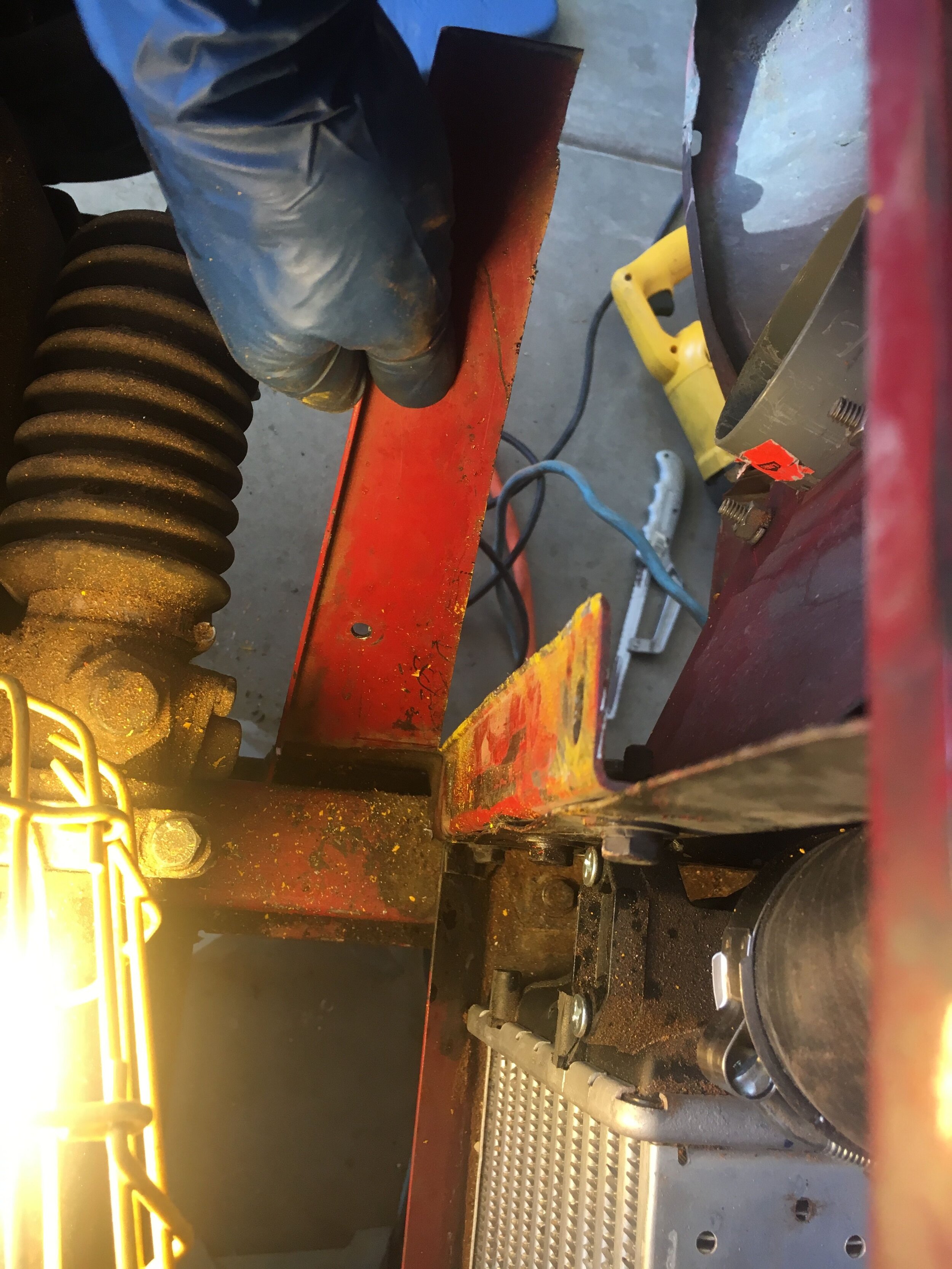
First, make a vertical cut just aft of the radius, and which reaches down approximately level with the bottom of the opening for the radiator core, as shown here:

Next, make a small horizontal cut of approximately .25” or less—but just sufficient to allow the vertical piece you have created to bend outward, as shown here. We used a small hack saw to avoid cutting too much metal and weakening the mount created by this operation:

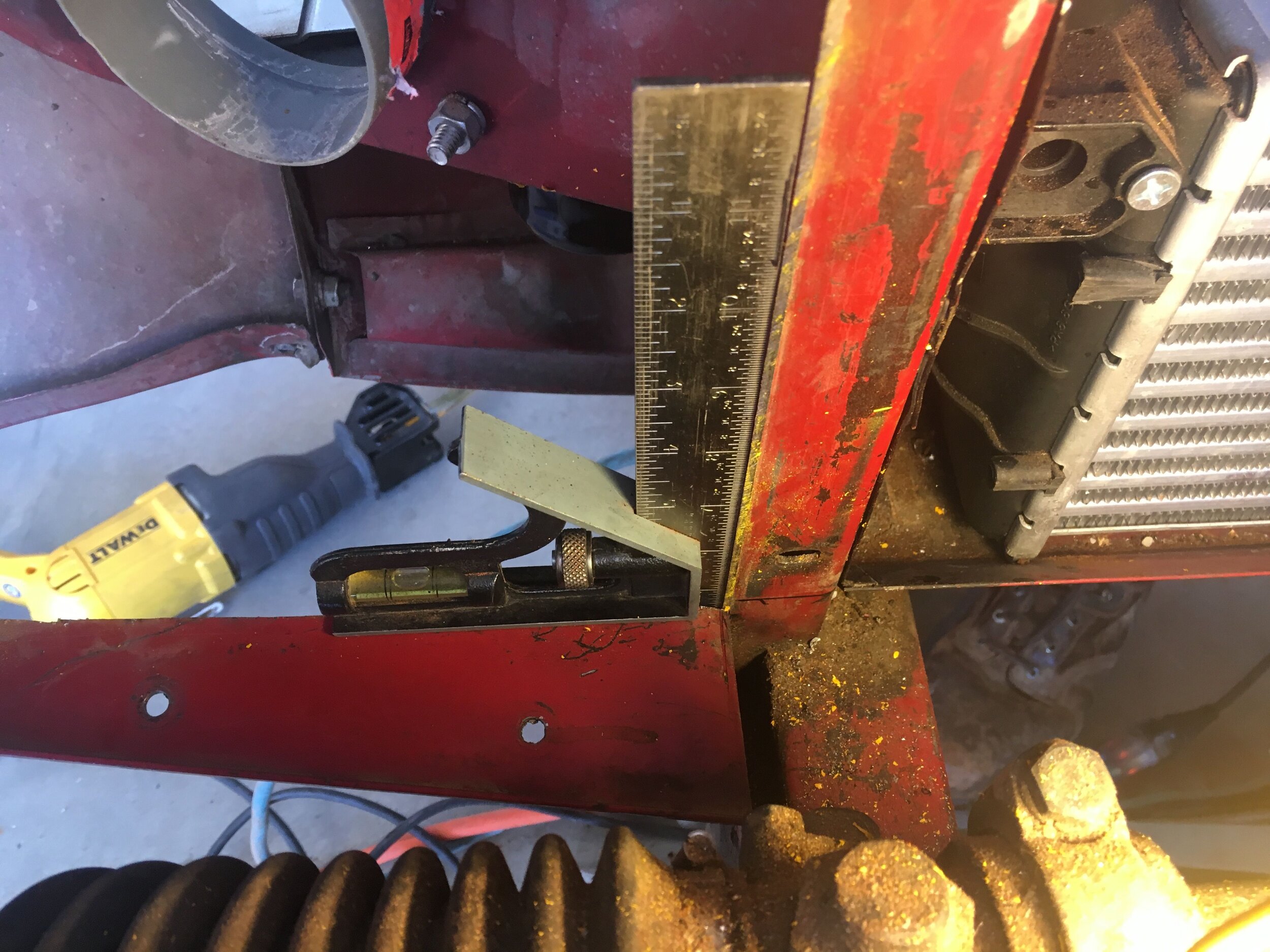
Now, carefully bend the piece you have created down until it is at 90 degrees from vertical as shown below. Take care to keep the piece aligned fore-and-aft as you bend it down:
Step 3 - Create the lower mounts
Once you have confirmed that the pieces are both at 90 degrees from vertical, set the new radiator in place to measure where to cut the pieces—which will now support the bottom of the VW Rabbit radiator:
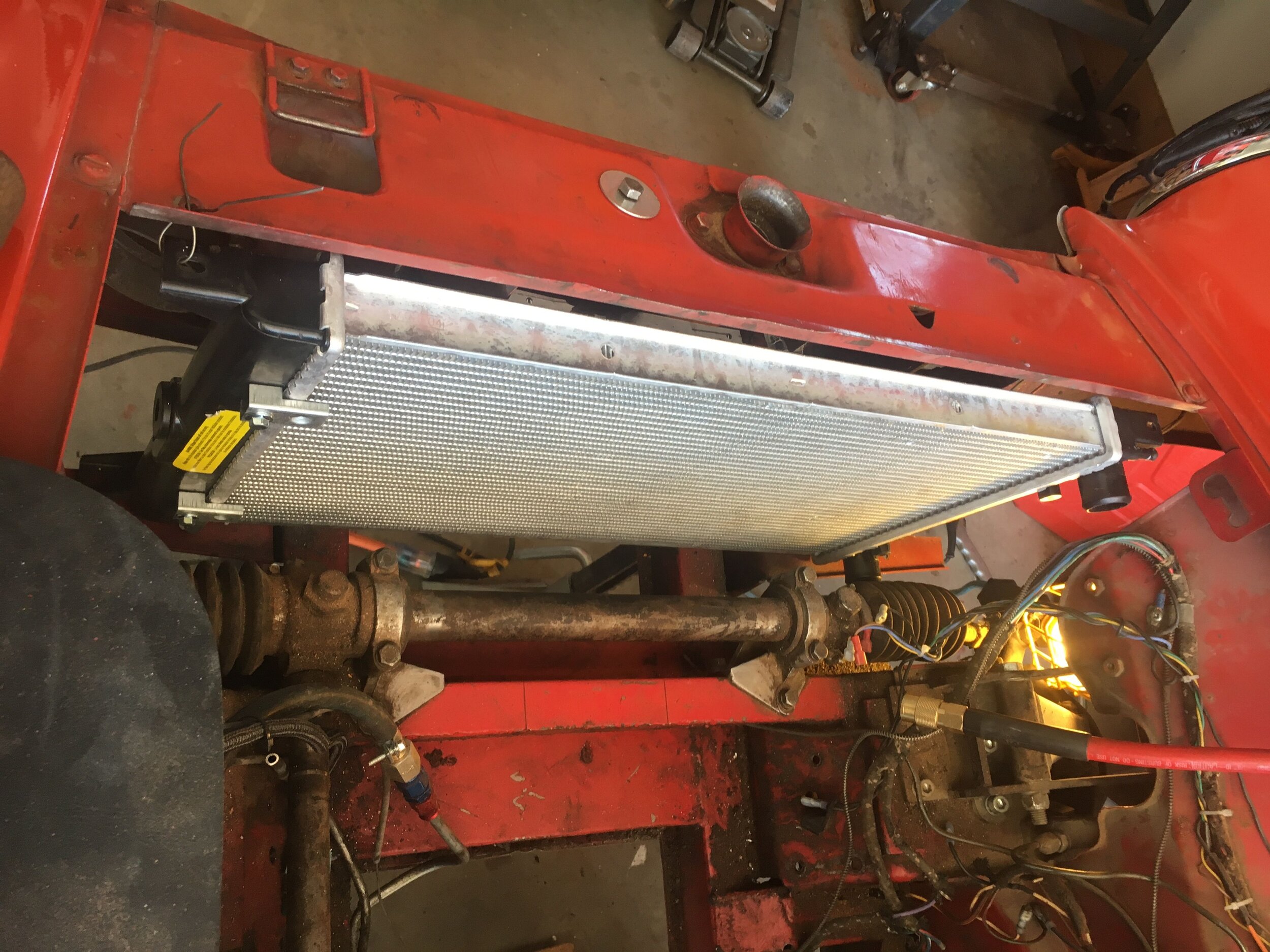
You will note that the radiator’s core is a small amount shorter than the opening in the body, as shown here. This is not a concern, as the gap will be filled with the top mount, which is made from aluminum angle iron:

Next, if necessary, you may have to make tabs to reach the radiator’s mounting ears. This owner did not find it necessary, and merely installed rubber bushes to insulate the radiator from shock and vibration—and to insulate the radiator from the ferrous metal of the body, which avoids electrically triggered corrosion:

If needed, measure and cut the supports just a bit longer than the radiator’s lower mounting tabs, which need sufficient room to receive small mounts that you will fabricate next. You will note that the author cut his supports a little too short, which complicated attaching the small mounts—better to cut a bit longer:
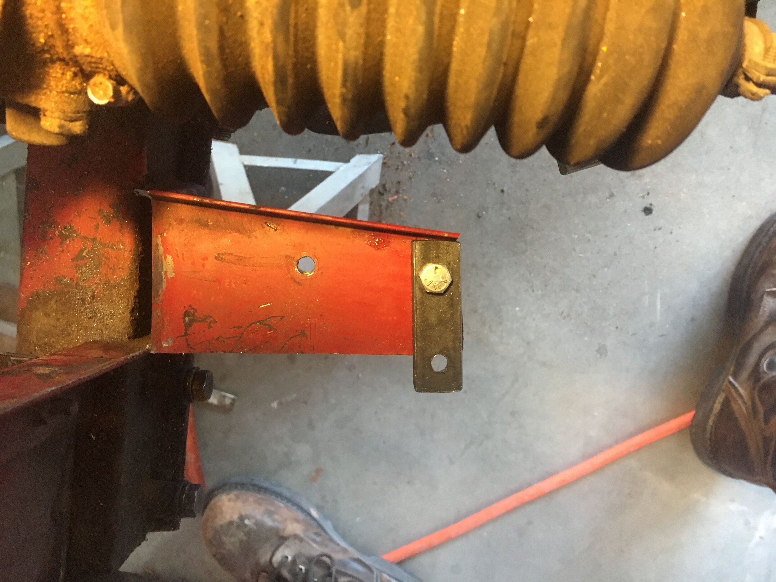
Here is a picture of the lower mounting tabs. These are made of 3/4” wide, 1/8” thick mild steel obtained from a local home improvement store, but you may use aluminum or whatever you have laying around:

Ensure that the radiator is held flush against the opening in the sheet metal, and then drill the supports to match the bolt holes in your mounts. Finally, bolt the radiator’s lower mounting tabs into place:

You can see in the above photo that it was necessary to insert a nut to obtain the appropriate height and keep the radiator core square with the opening in the sheet metal. This may be difficult to avoid, as precisely anticipating the radius created by bending the supports—yet without tearing the metal—is challenging.
If you live in a humid climate, you may wish to paint the exposed edges of the metal created by the operations to this point. The author’s car is in the high New Mexico desert, where rust is not an issue.
*Note: these photos do not show rubber washers, etc., to insulate the aluminum radiator from the ferrous metal of the body, in order to avoid electrically triggered corrosion. You should, however, include them.

Step 4 - Create the upper mounts.
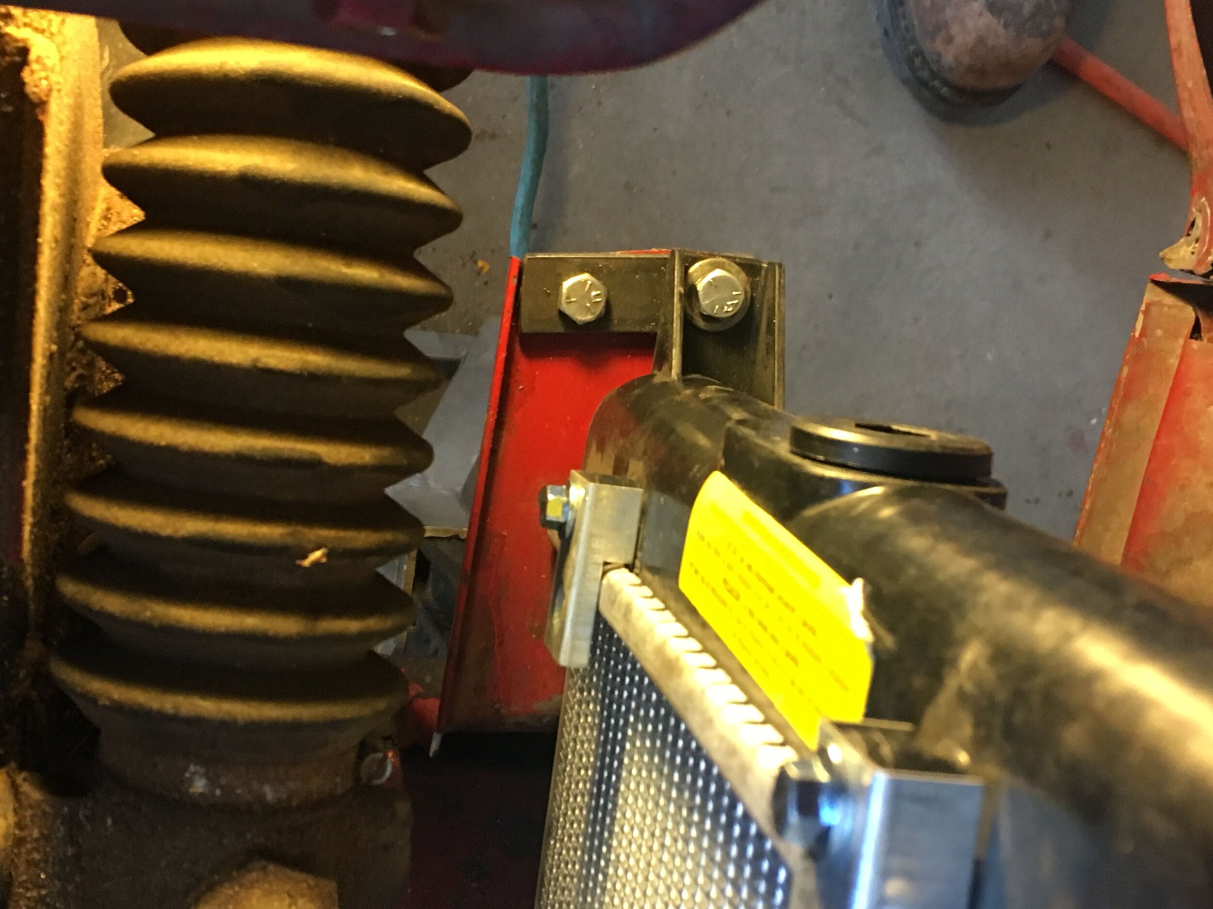
The radiator’s top mounting tabs present themselves very close to the Spridget’s sheet metal:

We fabricated simple ‘L’ brackets from aluminum angle iron, bolted them to the tabs, and then used clips to hold the brackets to the sheet metal. You could bolt or rivet the brackets instead:
A similar method was used to sandwich the radiator core’s aluminum top channel between the fans’ mounting tabs and brackets made from the same aluminum angle iron (the bottom of the fans were affixed to the core using run-of-the-mill pin mounts through the core):

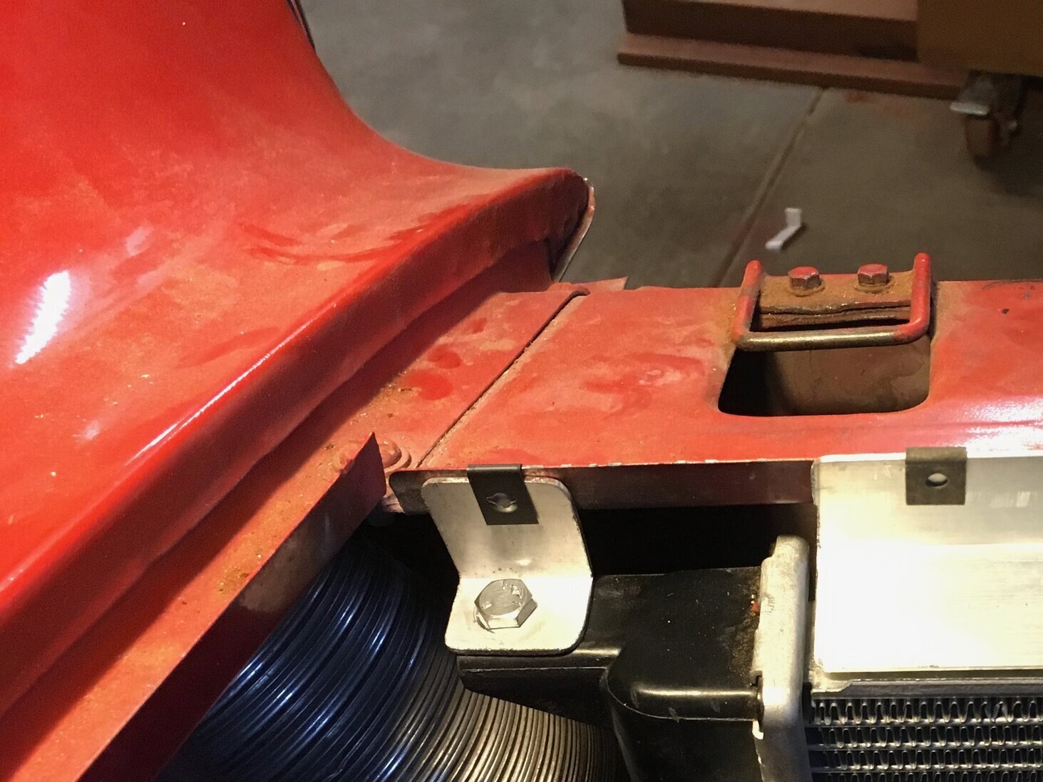
Next, cut a length of larger aluminum angle iron, place it over the small pieces affixing the fans, and clip (bolt, or rivet) it to the Spridget’s sheet metal, thus closing the gap created by the radiator’s core:
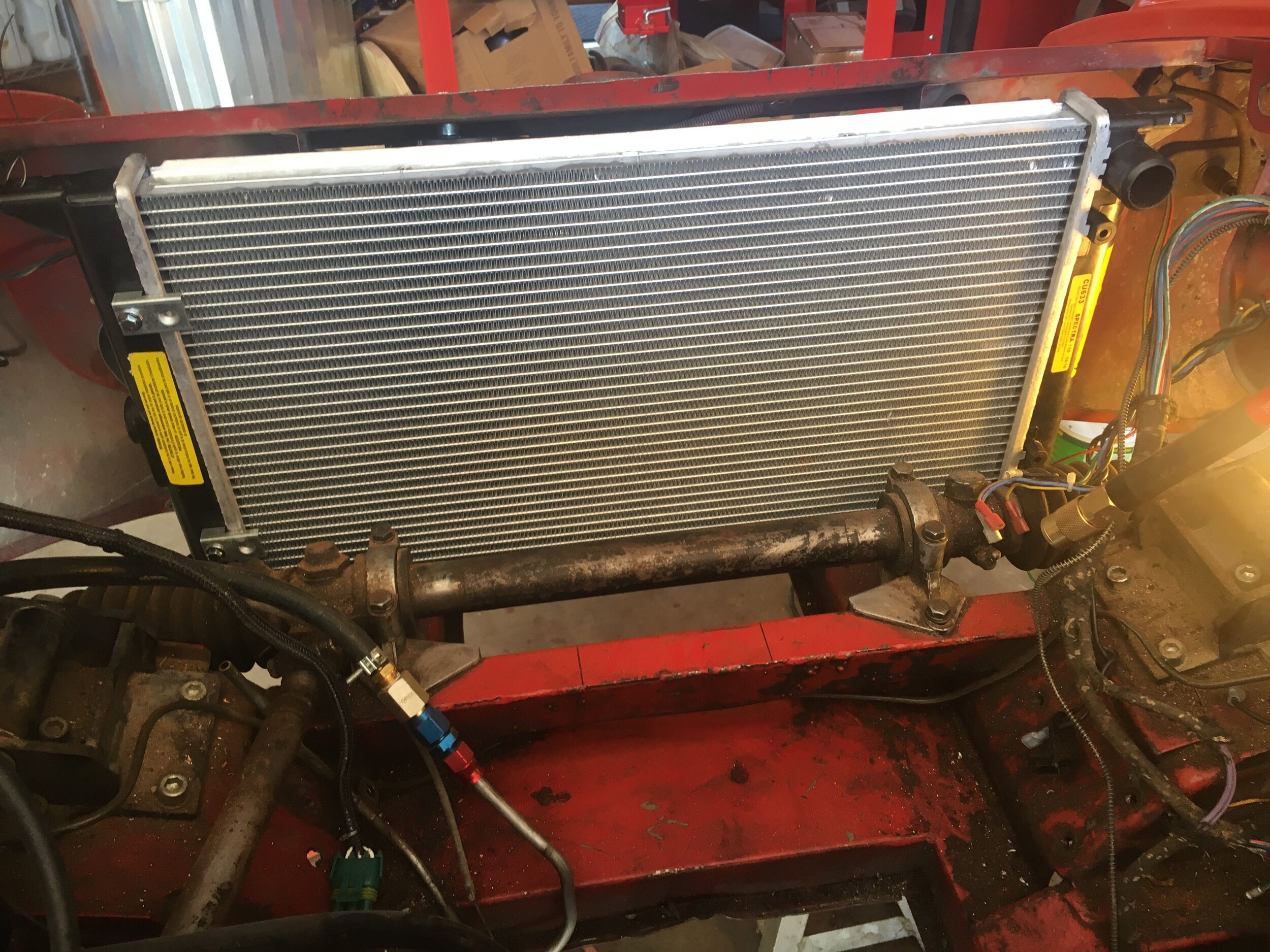
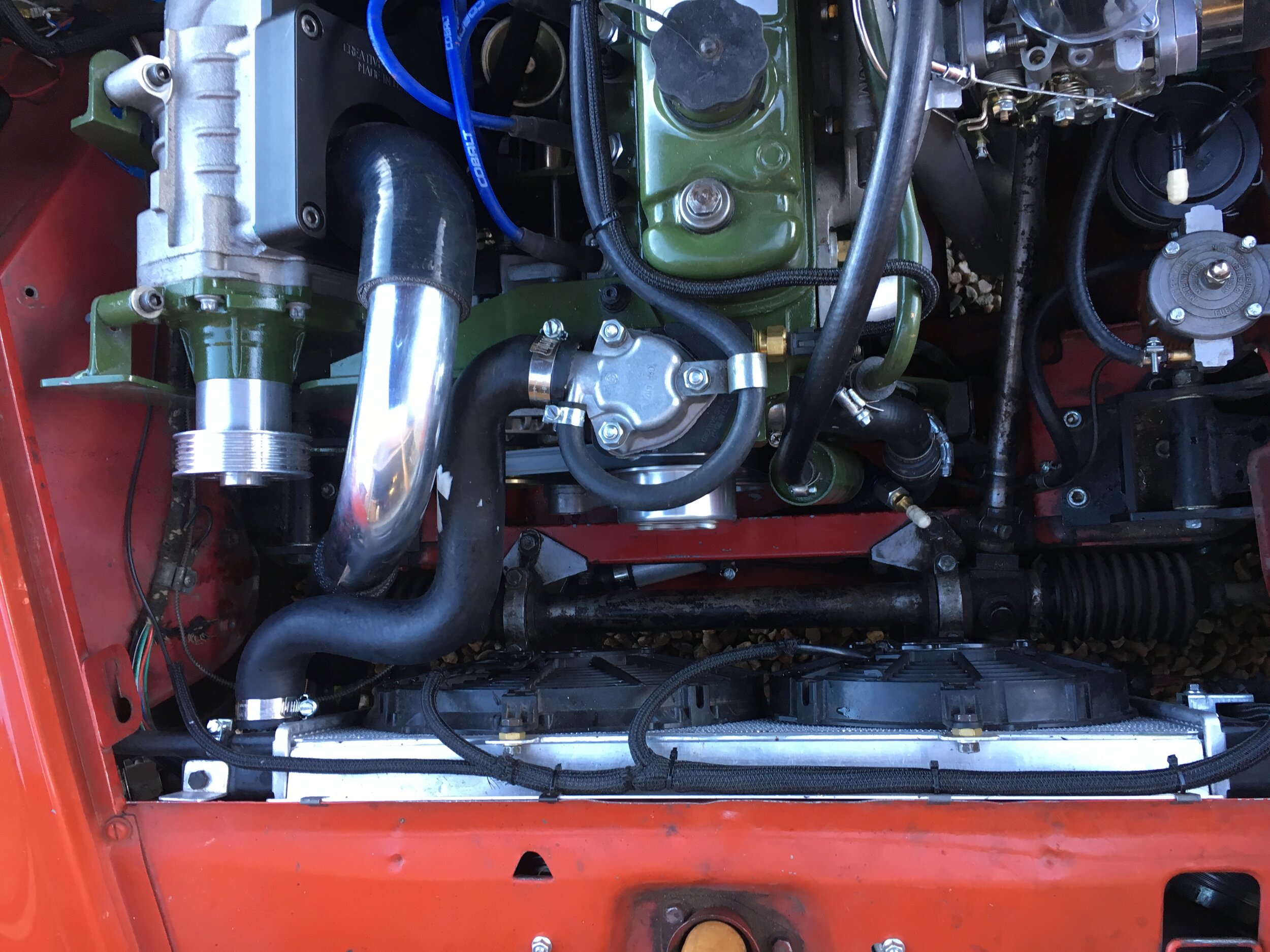
Here is the radiator securely mounted in the engine bay with the fans installed:

You can also see the lower radiator hose assembly in the above photograph—which we will turn to next. But note that the upright section of hose in this photo turned out to be too short; it needs to rise a few inches to the left-hand side of the crank pulley (indicated by the Sharpie lines on the steering rack crossmember) in order to meet the shortened OEM lower radiator hose.
Step 5 - Install the lower radiator hose assembly.
The lower radiator hose is comprised of two Gates no. 22271 1.25” hoses, which are the lower hose from a 2000 Toyota Camry (4 cylinder engine), joined with the 6” aluminum joiner tube listed at the outset of these instructions, in roughly the configuration shown here:

The upright ‘L’ will rise to meet a shortened, OEM Spridget lower 1” radiator hose, using the plastic 1” to 1.25” hose barb adapter listed above:

Measure and cut the two Camry hoses so that when joined with the 6” aluminum tube, the upright leg is in line with the shortened OEM Spridget lower hose. On the 1967 MG Midget test mule, this point was immediately in front of the left-hand motor mount (note the increased distance from the index line for the O.D. of the crank pulley when compared to the earlier photo):

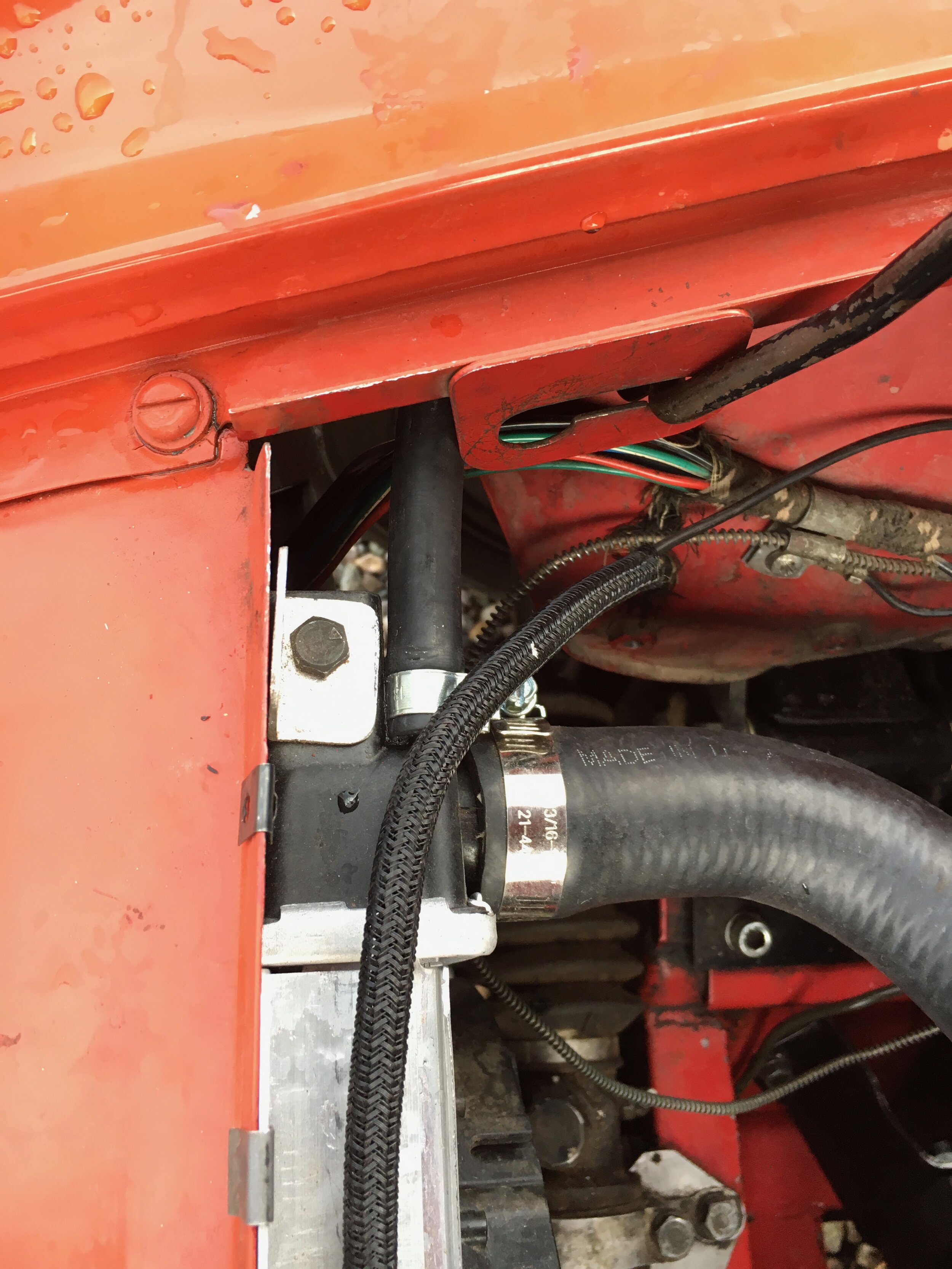
In the following image, you can see that the end of the hose clamp is preventing the lower hose from tucking up against the underside of the steering rack crossmember, and causing the rubber hose to touch the brake line:

Although the rubber will not transfer heat to the brake line as efficiently as the aluminum joiner tube and may not boil the brake fluid in the steel line (it did not in the test mule in the photos), you can simply rotate the clamp and zip tie the free portion of the hose to the crossmember to avoid contact.
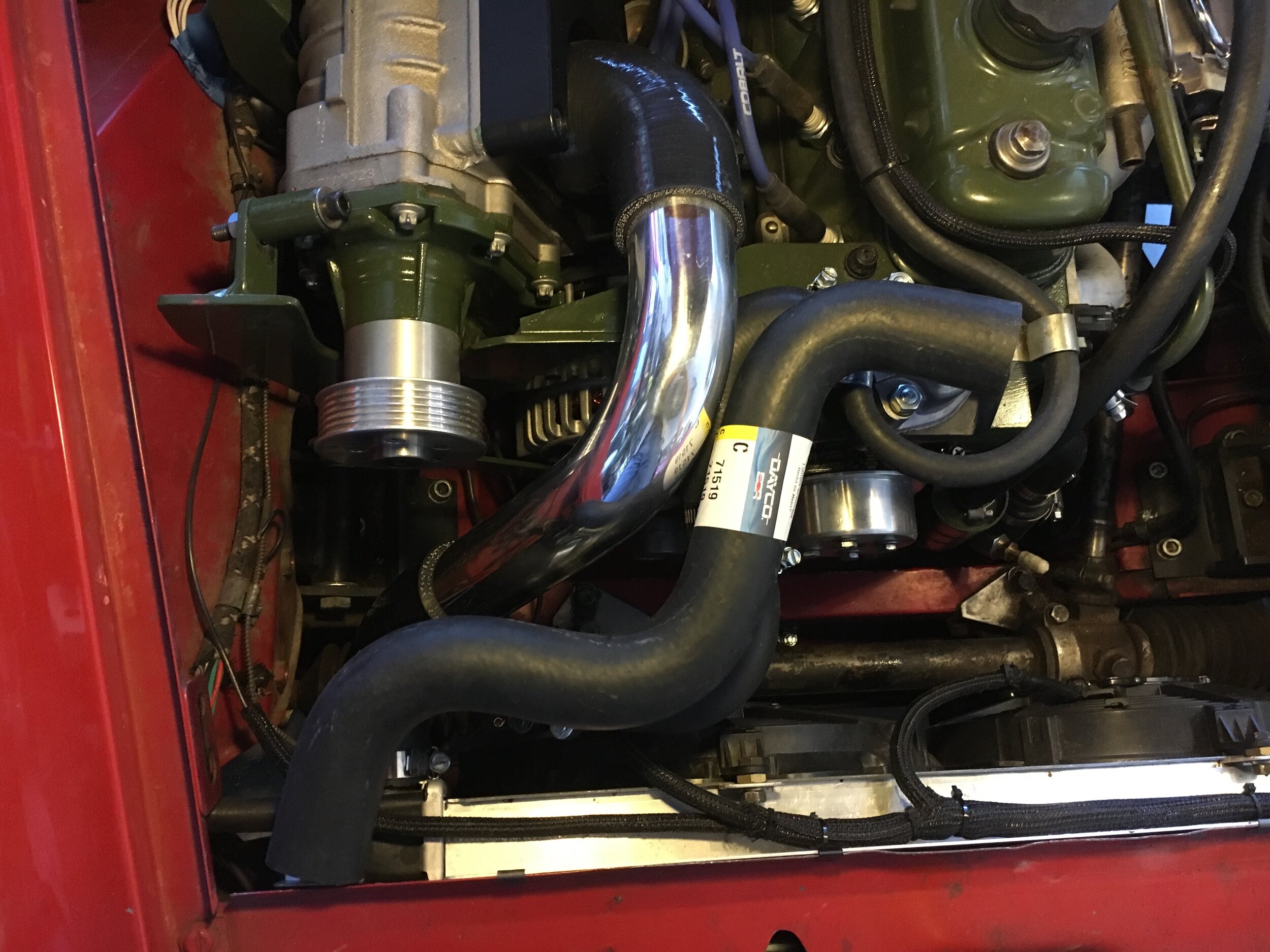
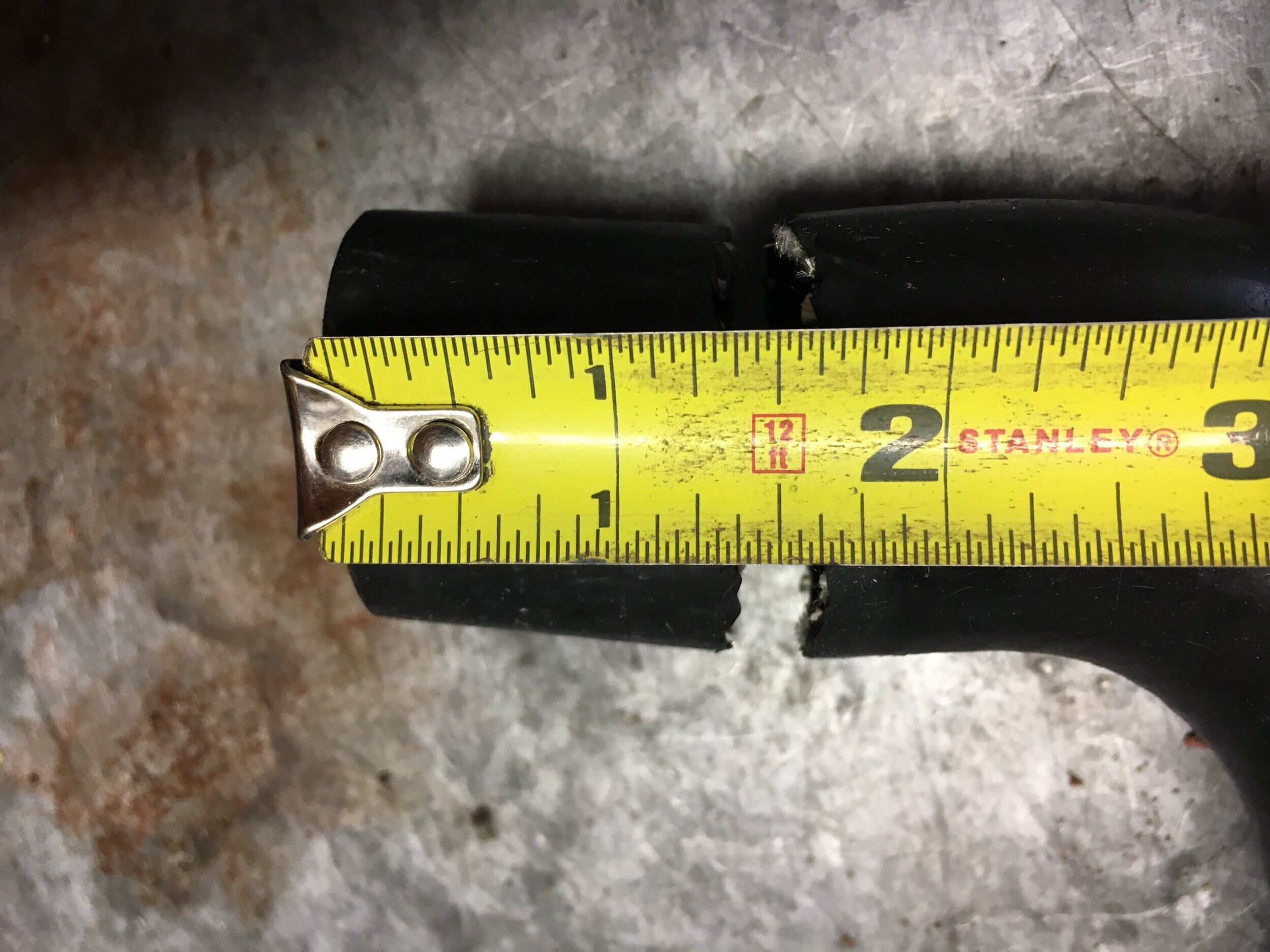
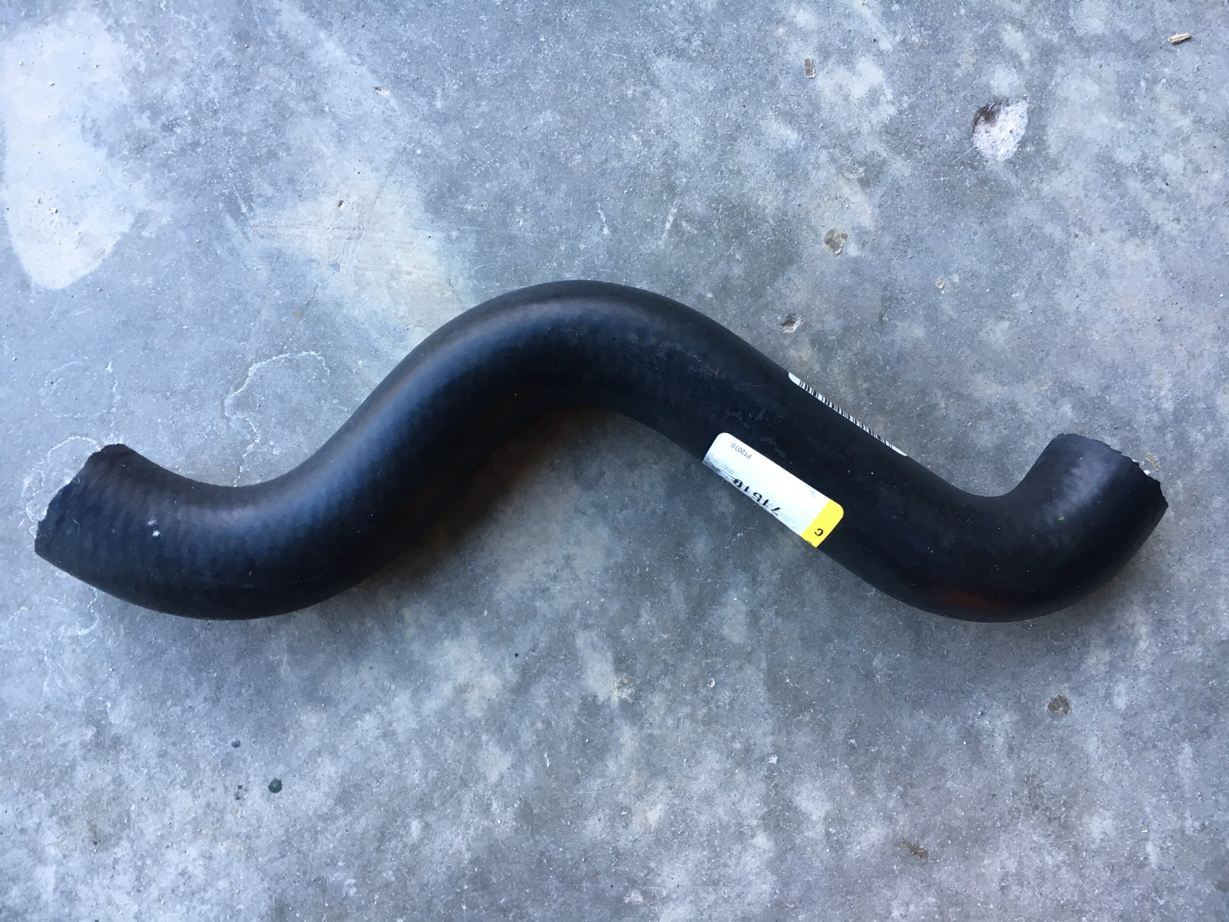
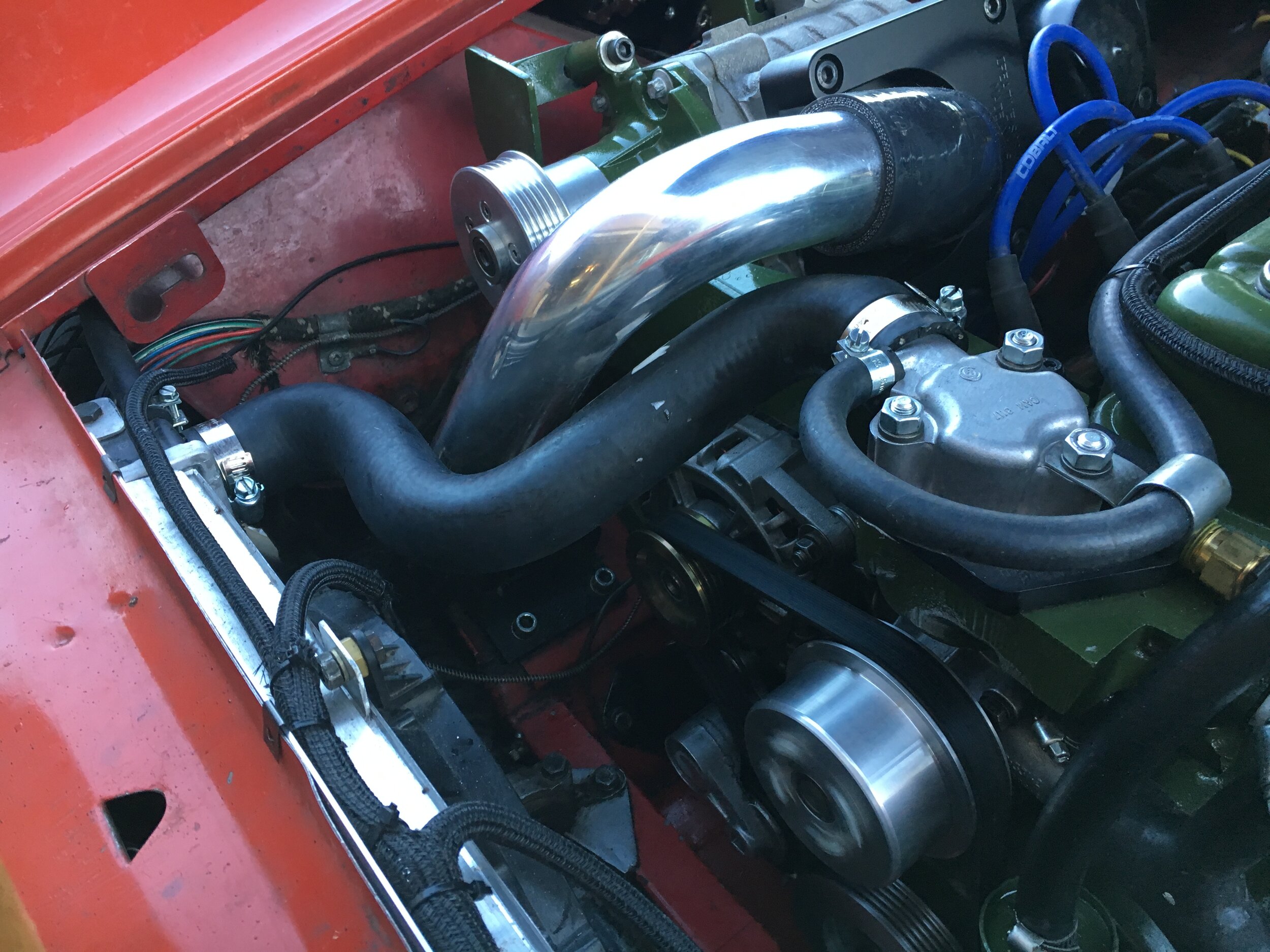
Step 6 - The upper radiator hose assembly
Both naturally aspirated cars and Spridgets running our DIY intercooled supercharger conversion discussed here use a single Dayco C71519 hose or equivalent, as shown in the following photo series.
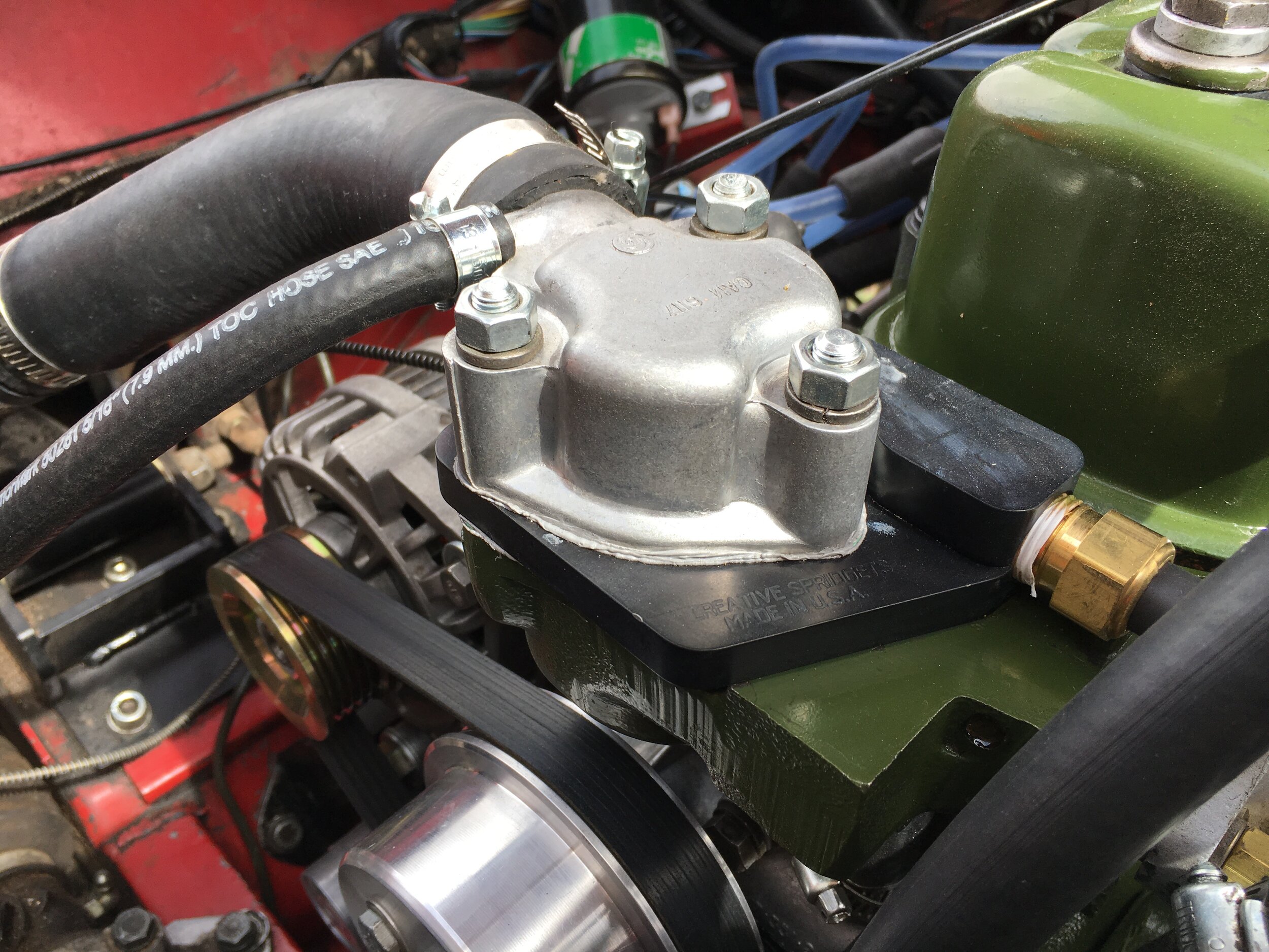
In essence, all you must do is trim 1-3/8” from both ends, then attach the end with the slightly tighter radius to the thermostat housing:

Step 7 - Plumb the expansion tank and steam hoses.
The VW Rabbit radiator used in this conversion requires an expansion tank that is part of the pressurized cooling system, as opposed to an overflow tank.
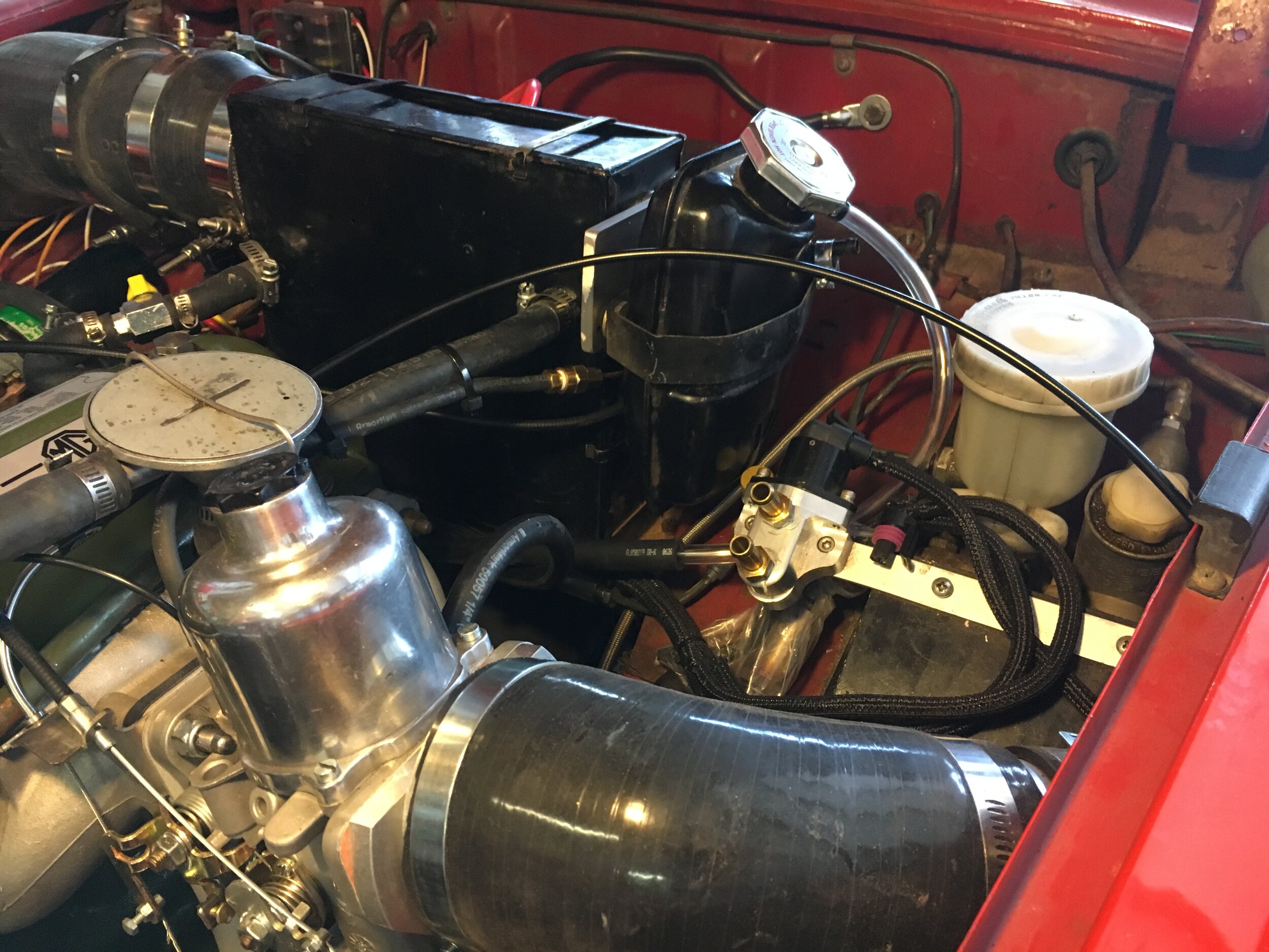
You can use an aftermarket aluminum tank, which may be had for surprisingly little money online, or you can use a standard-issue Spridget metal overflow tank, which can easily be converted to function as an expansion tank by fitting it with a pressure relief cap. (This tank’s location arises from relocation of the heater fresh air intake to allow room for a supercharger):

If you use the OEM tank, make sure you distinguish its inlet—which connects to a tube that protrudes beneath the surface of its contents—and the overflow, which should be routed out to the road beneath the chassis.
The cap must have sufficient reach to seal the tank. We found that a universal Stant no. 10228 rated at 7 lbs. worked well; you may wish to select a cap with a higher pressure rating.
Regardless of which tank you use, we recommend that you connect its inlet to both the overflow/steam line from the radiator’s small nipple near the inlet and the steam nipple on the Mini Cooper thermostat housing. Use the 5/16” brass Tee fitting in the parts list.
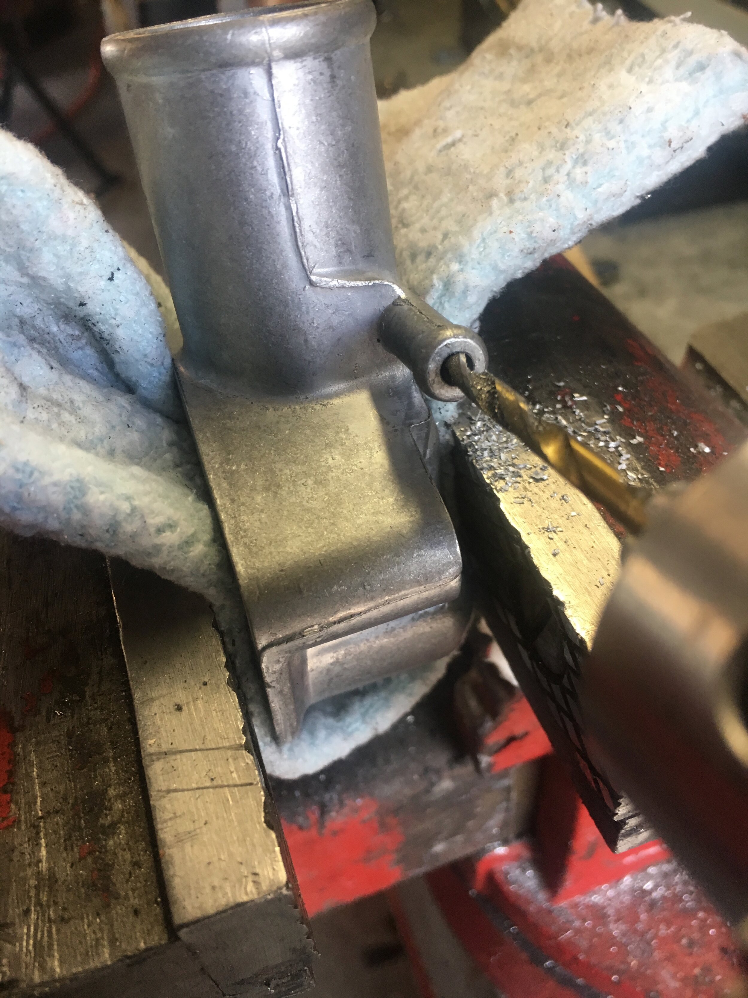
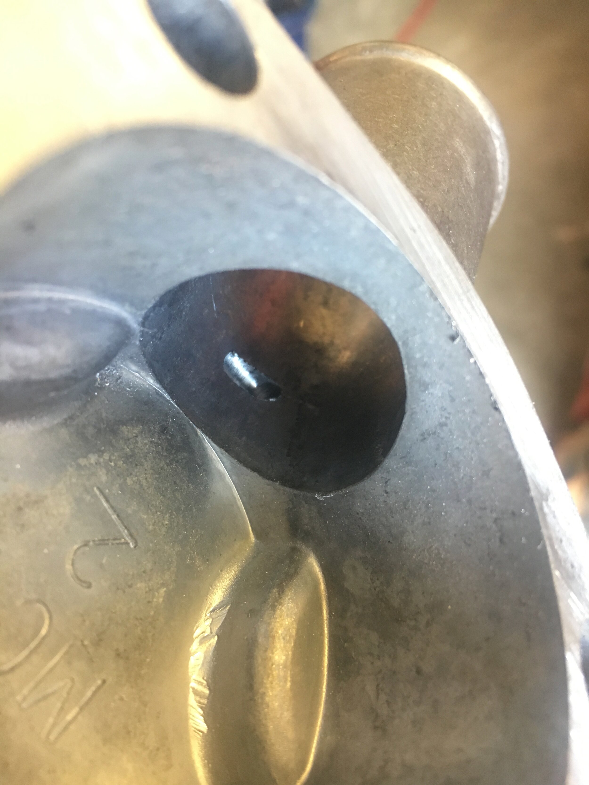
First, you must drill out the Mini Cooper thermostat housing, as shown in this photo series:
Second, note that the high-flow housing often is delivered with casting marks that must be removed to avoid leaks at the gasket:

Use a flat file or sandpaper, but if using sandpaper, either use a sanding block or hold the sandpaper on a flat work surface and rub the housing back and forth firmly to keep the mating surface flat.
Next, connect a length of 5/16” heater/overflow hose between the thermostat housing’s nipple and the brass 3-way Tee—which is connected to the expansion tank’s inlet and also receives the hose from the radiator’s steam nipple:
Note again that in the above photos, the OEM-style Spridget expansion tank and the heater fresh-air intake have been relocated to make room for the Eaton M45 supercharger used in our DIY supercharger conversion discussed here. You may locate the expansion tank wherever is convenient.
We used EFI-spec hose clamps on the 5/16” expansion tank hose, as we found that they seal better on smaller diameter hoses.
Step 8 - Wire the fans and relay.
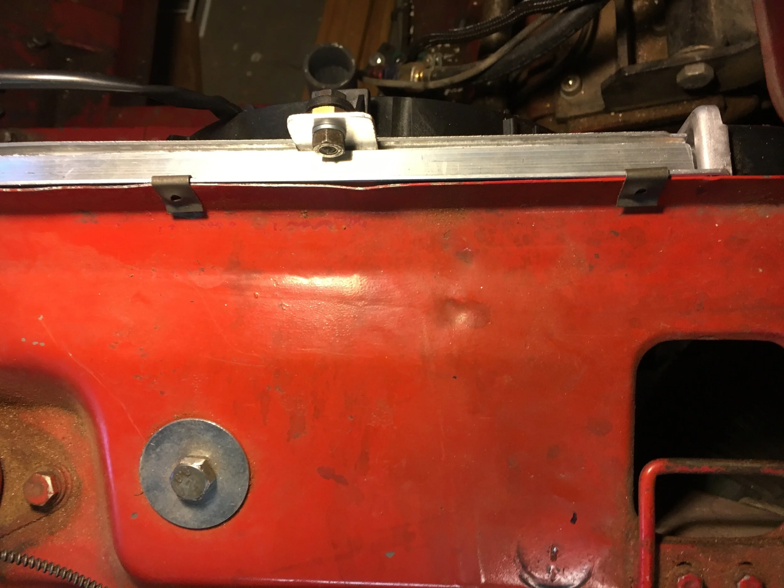
We chose to locate the relay on another piece of aluminum angle iron bolted to the left-hand top radiator mount and immediately above the fan switch, which is located in the left-hand radiator tank.

The zip ties holding the relay in place are temporary; the author did not have an appropriate fastener handy.
Connect a fused (25 amp) power lead to both the trigger circuit’s positive lead and the power input lead of the relay, then connect the power output lead to the blue wires coming from the Spal fans.
We used a siamese spade connector to attach one side of the temperature switch to ground both the relay’s trigger circuit and the fans’ black leads. The other side of the switch is connected to a chassis ground:

Step 9 - Fill and test the system.
Check all hose connections to ensure that all hose clamps are in place and secure.
First, open the heater tap and fill the expansion tank about halfway with your choice of coolant and distilled water.
Now, fill the cooling system through the top radiator hose after removing it from the thermostat housing. Place a receptacle and rag underneath the housing’s hose barb, and use a funnel if you prefer to fill the system:

Slowly fill the system until coolant begins to trickle from the thermostat housing. Now, move the end of the top radiator hose just below and just above the housing and observe the level of the coolant inside the hose. Add coolant as necessary until the level inside the hose rises just even with the bottom of the housing.
Now, replace the top radiator hose and double check all of the clamps.
NOTE: before you start the engine, use a jumper wire to ground the relay and make sure the fans are rotating in the correct direction.
Start the engine and let it idle while checking for leaks and watching the temperature gauge. When the engine has reached operating temperature, carefully check the temperature of the top radiator hose and the radiator’s left-hand tank (do not burn yourself) to ensure that the thermostat has opened and coolant is flowing through the radiator.
If you have fitted a 180 F. fan switch in the VW Rabbit radiator and a 180 F. thermostat in the engine, the fans should cycle on when the car’s temperature gauge hits 190~91 F. and switch off at around 188 F. (The engine may run too cold in winter weather, in which case you may wish to install a 190 F. thermostat.)
Thereafter, regardless of how hot the ambient temperature or the load on the engine, the engine temperature will cycle between 188 and 191 F. (86.7 and 88.3 C.) as shown here (freshly rebuilt engine at idle after a 30-minute highway run):

Allow the engine to cool completely, carefully release the expansion tank cap, and top up the tank to approximately 1/2 full.
At long last, you can now focus on enjoying your Spridget and forget about nervously eyeing the temperature gauge!